Here is a description of a practical load box suitable for high power stereo amplifiers. It also provides facilities for simple and rapid switching between speaker systems, as required for comparative tests.
Until now, we have used a variety of load boxes/and which, in their way, served the purpose well enough. However, it was becoming increasingly obvious that changing amplifier fashions served to emphasis the limitations of these units, and that the time had come to produce something more suitable.
To name just two factors which were most obvious there is (1) the fact that almost all amplifiers these days are stereo, and therefore require two load resistors, and (2) the fact that amplifier ratings can be a good deal higher than would have been considered likely, even 10 years ago.
As an example of this latter aspect, load resistors can typically be called upon to dissipate power in excess of 60 watts. This figure is not unusual as the per-channel rating of some high-powered stereophonic amplifiers.
Similarly, it is not unusual to encounter guitar amplifiers with rated powers of the order of 100 watts.
And, having decided to construct a new unit, we considered what other features we could incorporate which would make it as versatile and convenient to use as possible. The end result is something which, while being relatively simple and inexpensive, should appeal to anyone who has a regular need to measure amplifier power.
First, we had to consider how many values of load resistor we should provide, and what these should be, while keeping in mind the need to use readily available switches and other components. While it is easy to evolve "smart" switching systems which provide great variety of resistance values, there is a very real risk that this will call for switches and resistors which arc too expensive, hard to obtain, or both.
We finally settled for four load values: 2,4,8 and 16 ohms, as being sufficient to cope with most practical situations. While it is true that there may be minor differences between these and the values specified by some manufacturers -- i.e. 15 ohms rather than 16, or 3.75 rather than .4 -- these are not likely to cause any serious problems. Provided we know the value of the load, and base our power calculations on it, the error introduced by presenting a slightly different load to the amplifier will be small.
These four values are selected by means of a 2-pole, 7-position switch.
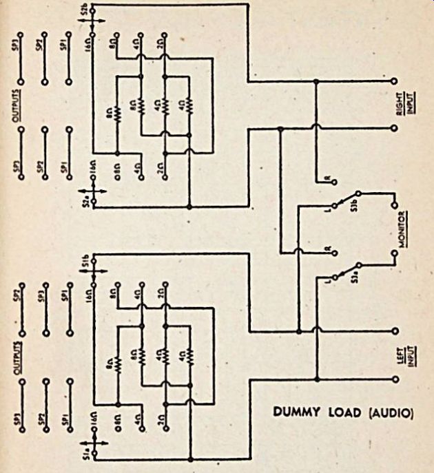
--------- DUMMY LOAD (AUDIO): Main feature of the circuit is the
use of two resistors for all load values, thus doubling the wattage
rating. Switching facilities between speakers is also provided. Wiring
is relatively simple.
(We will discuss the purpose of the other three positions in a moment.) The method of connection and the values of resistors chosen are such that two resistors are required to make up any value. This means that the wattage which can be dissipated will be twice that of the rating of the individual resistors. Thus if 50-watt resistors arc used throughout, the unit could handle 100W in each channel . In a special case, where only a single channel was involved, the right and left hand loads could be connected in series or parallel to provide a 200 watt rating.
While we used 50 watt resistors in the unit we built, such large ratings may not be justifiable in every case, and this will be for the individual constructor to decide. Fifty watt resistors, at 5% tolerance, are quite expensive, and many builders may be content to settle for 20 watt units (40W total), or 10 watt units (20W total).
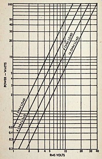
----- This graph will simplify power output calculations.
The resistors were vertically mounted in a standard equipment case measuring 9 x6 5-8x5 5-8 inches deep. Ventilation was provided in the form of louvers in the sides and two rows of V* inch diameter holes along the back panel. This is necessary to keep the temperature rise of the resistors within acceptable limits.
Both sides of the loads are isolated from the case to reduce to a minimum the possibilities of shorts and instability. Care must be taken with all connections to ensure low residual resistance. No special layout is necessary but the wiring for each channel should be kept separate to facilitate assembly.
The further three positions on the load selector switch are brought out to terminals on the front panel of the unit. These can be used for connecting capacitors across the output of the amplifier for stability tests or for connecting various speaker systems. The latter facility is very useful when it is desired to make a subjective comparison between speaker systems, by switching rapidly from one to the other.
In regard to stability tests, current standards require that they be made with no load across the output, other than the nominated values of capacitor. The load box thus satisfies this requirement.
Another facility is a pair of monitor terminals. These can be switched to cither channel and permit the easy connection of a CRO, voltmeter or other measuring device to the channel under test. The switch is a two-pole, two-position unit with "make-after-break contacts. A switch with "make- before-break" contacts must not be used because both channels of the amplifier would be connected in parallel at switch-over.
In many amplifiers this is a sure formula for destruction.
The unit in its final form is suitable for all normal amplifier tests such as power output, frequency response, cross-talk, and stability. Damping factor measurements can be made easily by disconnecting the load.
One point to be kept in mind when using the dummy load is that the loads should not be switched when operating at a high power level.
This is to avoid damage to the switches and also to the amplifier.
This precaution is not necessary when making comparison tests of speakers because these tests arc made at a relatively low power level.
PARTS LIST
1 metal case, 9 in x 6-5/8 x 5-5/8 in.
1 front panel to suit.
1 carrying handle.
4 8-ohm resistors (5% or better).
4 4-ohm resistors (5% or better).
2 2-pole, seven-position switches.
1 2-pole, two-position switch, with "make-after-break "contacts.
9 red terminals.
9 black terminals.
3 pointer knobs.
4 rubber feet, screws, nuts, hook-up wire, solder, etc.