EFFICIENT procedures in the servicing of radio tube troubles will shave valuable minutes off repair time. Our approach is based on the premise that the preliminary testing of all tubes in a set is (a) needlessly time-consuming and (b) inconclusive in many in stances, due to the inadequacies of a tube checker.
Need for stage localization tests
Rapid servicing is made possible by localizing trouble to the section and stage involved; then only a single tube will often have to be checked. Procedures to use for different symptoms are summarized in the pages that follow.
One or more tubes don't light
If the set is a straight ac receiver and a (glass) tube is observed to be unlit, resistance-check the filament of this tube. To determine if a metal tube's filament is not lighting, touch the tube momentarily. (Do this only when the set is turned on after having been off for an appreciable time. If a tube is touched when it has been permitted to become very hot, a burn is likely.) When the set is an ac-dc type and no tubes light, resistance check the filaments of the tubes, withdrawing the tubes from their sockets, one at a time. Start with the high-voltage filament types (such as the 50L6, 35Z5, etc.) since these are the likeliest to open.
If only some tube filaments in an ac-dc set are seen to light, a shorted tube is probably present. Test the tubes in a tube-tester, starting with those which were seen to light or which were warm to the touch. These are the tubes among which the shorted one is likely to be found. Check for leakage between elements. A heater-to-cathode short is generally responsible for the symptoms cited.
In some cases, a short of this type occurs only when the tube has heated sufficiently; give the suspect tubes a chance to "cook" in the checker for some time.
Tubes in an ac-dc set may not light because one of them isn't fully in its socket, causing the filament circuit to be interrupted.
Enlargement of the socket keyway may have permitted such an inadequate insertion or the key on the tube may be broken.
Sometimes series-connected tubes won't light because two or more of them are in the wrong sockets. Infrequently, a wrong tube type is in some socket (due to an improper substitution by the set owner). The familiarity with tube line-ups and positioning that comes with experience will enable the service technician to spot such troubles quickly.
Intermittent filament troubles
When an ac-dc set plays intermittently, see if the filaments re main lit when the set stops playing. The pilot light (if one is used) will go out if the filament circuit is interrupted, calling attention to this condition. This statement does not apply if the pilot light is not in series with the tube filaments.
A defective tube filament is frequently responsible for intermittent troubles. A thermal fault is often present in these cases.
Although the filament is broken, the two sections make mechanical contact when the tube is cold. When the filament heats, it expands and the broken sections part, causing an interruption of the filament circuit. The current flow stops allowing the filament to cool. Contact is now re-established and the tube begins to function once more, until expansion again opens the circuit. The radio stops playing, of course, during the time the filaments are open.
One of the best and fastest ways to locate the source of such trouble (in series filaments) is to check the ac voltage across each filament when the set has gone off. Zero voltage will be measured across normal filaments, since no current is passing through the circuit. When the voltmeter is placed across the open filament, however, the meter completes the circuit (Fig. 801). Current now flows and the voltmeter will register. (The small amount of current, however, will not be enough to light the tubes.) Since the meter's resistance is large, in comparison with that of the tube filaments, almost all of the line voltage will appear across it. If line voltage, then, is read when an ac voltmeter (i.e., the ac section of a voltmeter) is connected across a tube filament, that tube is the intermittent one. When a make-and-break process takes place in the filament during the time the voltmeter is connected across it, the voltage measured will fluctuate between zero and line voltage.
The novice technician may wonder why such a method is used.
Why not check the tubes in a tube tester? The answer is that the tester will not generally reveal such trouble when a conventional test is made.
In some instances, the duration of the set's dead interval--i.e., the time of filament open-circuit--is so short that a voltage test of all the filaments cannot be made before the set starts to operate again. One possible way of locating the trouble lies in applying excessive filament voltages to the suspect tubes. The method is a controversial one but no damage will be done to a good tube if...

Fig. 801. An ac voltmeter can be used to locate an open filament.
... the precautions cited below are observed. Only indirectly heated tubes should be subjected to such treatment; direct-filament types will blow quickly if a filament voltage in excess of their rated one is applied.
The method is this: Put the suspect tube into the tube checker. (Start with the tube that has the highest filament voltage rating and work down to the lowest voltage types.) Apply the correct filament voltage and let the tube heat for awhile. After a minute or so, raise the filament voltage by adjusting the filament control on the tube tester. (Don't apply excessive filament voltage to a cold tube.) If the tube is a 50L6-GT, for instances, the filament voltage applied to it may be increased from 50 to 60, then to 70, all the way up to a maximum of 100. Watch the inside of the tube all the while, noting whether the tube "blinks"--i.e., varies in its filament lighting. If it does, the tube is defective. A second caution: Don't apply excessive voltage to the tube filament for more than a moment. The whole procedure should be performed very rapidly. It may be repeated once if no blinking is noted the first time. If the tube seems normal, go on to the next one. It is advisable to apply no more than double the normal filament voltage to any tube.
When the tube tester provides a pilot light in series with the filament of the tube under test, blinking of the pilot lamp will indicate that the tube is defective.
Excessive filament voltage should not be applied to miniature tubes since the close spacing of elements present in this type of tube makes the procedure dangerous. Never press the emission button on the tester when the filament voltage is above normal.
Another method of localizing an intermittently opening tube filament lies in resistance-checking the filament of each tube while it is still warm. This involves continuity-testing every tube as quickly as possible after the set has been turned off. When the tube is warm, a thermal break is more likely to manifest itself than when it is cold.
In a few cases, particularly in old sets, when a tube like the 25Z5 is the source of trouble, filament expansion and contraction may be noted by visual inspection. This method is faster than a voltage or tube-tester check and is worth trying in the case of a short duration intermittent.
Sometimes intermittent lighting of a tube filament is due to a poorly soldered connection at the tube prong. Inspection will frequently indicate whether this is a possibility. If a prong looks as though the soldering may be inadequate, hold a soldering iron against it to renew the connection. A small amount of solder may be applied to the prong when necessary.
Poor contact of socket and tube filament prongs may be responsible for intermittent filament lighting. The defect may be readily checked for in certain socket types by placing a screw driver blade between the suspected contact and the tube prong associated with it. If a spark is seen and the filaments now light, the contact is imperfect and should be improved. In the case of other socket types, test the contacts by wiggling the tubes. If intermittent filament lighting is produced by such action, a poor connection may be present. To remedy the condition, try pressing the filament socket contacts closer together with a thin sharp pointed tool, such as a scribe. (This is done at the top of the socket.) In an ac set, socket-contact trouble may be checked for by measuring the voltage between the "hot" filament socket contact and ground, and the "hot" tube filament prong and ground (if this tube prong is accessible at the socket). If voltage appears at the socket contact but not at the tube prong, contact is not being made between the two.
Set doesn't play but tubes light
When the set doesn't operate but the parallel filaments light, click tests can be made to locate the faulty stage. The procedure is as follows: Remove the power amplifier tube from its socket and listen for a clicking sound, holding your ear close to the speaker.
If no click is heard, test the rectifier in a tube checker. If the rectifier is defective, test the B supply for a short before replacing the tube. (This test may be made from the top of the rectifier socket, avoiding the necessity of removing the chassis from its cabinet.) If a click is heard, remove the tube that feeds into the power amplifier. A louder click should now be heard. Work backward toward the antenna input, removing tubes one at a time. When a tube is found whose withdrawal does not produce a distinct click, a defect in that tube may be present. The clicks are produced by the interruption of current that takes place in the plate circuit of the withdrawn tube. This interruption constitutes a pulse of current that is amplified in succeeding stages.
In cases where click tests seem inconclusive and the set is out of its cabinet, disturbance tests may prove helpful. To make such tests, use a long wire, or preferably, the lead-in from an external antenna. Rub this wire against the grid of the last tube (the power amplifier). A scratchy sound will be audible in the speaker if the power amplifier, rectifier and speaker are functioning. Now disturb the grid of the preceding tube. The scratchy sound should be louder. Work backward in this way toward the first tube. When a tube is reached which produces no sound when its grid is scratched, a defect in that tube (or its circuit) is indicated. When no scratch is produced at the power amplifier grid, a defective rectifier or power amplifier tube may be present.
The procedures just outlined may be dispensed with if the set sounds "alive"--i.e., has a high noise level and sounds as if it were tuned between stations. In this case a defective converter (or oscillator, if a separate oscillator and mixer are employed) should be looked for. If the set is out of its cabinet, this diagnosis may be quickly verified by touching the lead from an external antenna to the stator terminals of the rf and oscillator tuning capacitor sections. Hum or noise will be heard, or one or more stations will come through when the rf stator is touched; touching the oscillator stator, however, will generally produce no aural effects if the oscillator is inoperative.
When a converter with an external grid cap is used a poor solder connection inside the grid cap may make the converter wholly or intermittently inoperative. If the cap looks at all suspicious, try renewing the connection by holding a soldering iron to the cap briefly, adding a little solder to the top of the cap.
Set plays on some stations
When the set plays on only a portion of the dial, oscillator trouble is often responsible. In some cases where the oscillator is completely inoperative, one station will nevertheless come through. This takes place when a strong station is present near the 550-khz end of the dial and the if stages are not too accurately aligned. The set acts like a tuned-rf receiver in this case and passes the single station.
Converter tubes with defective oscillator sections will often check OK in a tube tester. Substitution is the only safe test for such tubes.
Station drift
When the radio needs to be retuned after it has been on for a while, either because the station originally tuned in is no longer coming through or is coming through distorted, the converter or oscillator tube may be defective. A quick preliminary inspection of the dial cord may be made before the tube is changed. Too tight stringing of the cord may be responsible for an undesired movement of the tuning capacitor that produces effects similar to those caused by oscillator drift.
Receiver volume below normal
When the set plays low but all stations are received and no hum or distortion is audible, try a new rectifier, power amplifier and audio voltage amplifier, in that order. (Don't waste time testing the rectifier and power amplifier in the tube checker-defects in these tubes that reduce volume are often undetected by such a test since the tester does not put these tubes under their normal heavy load.) After this, test the remaining tubes in a tube checker or by substitution.
When the set's volume drops below normal after a while or does not reach normal volume until the set has been in operation for some time, a defect in the rectifier or power amplifier is quite possibly the source of the trouble.
If a relatively slight reduction in volume is present, see whether the pilot lamp is burned out. If it is, replace it. When the pilot light is connected across a section of a 35Z5-GT (or similar tube) filament, an open in the pilot lamp will cause an increased voltage drop in the rectifier filament section across which the pilot light is connected (Fig. 802). The voltage across the remaining rectifier filament section, as well as that present across the filaments of the other tubes, will be reduced proportionately. The set volume will drop slightly (but noticeably) in consequence.
When set volume is normal at the high end of the band but inadequate at the low, a defect in the oscillator or converter tube may be responsible.
Distortion
Distortion may be defined as a reduction in receiver fidelity. To determine whether fidelity is normal, the service technician must know what to expect from a particular set. This is not always simple for the novice because some sets are rather poorly designed and have abnormal levels of distortion even when in "perfect" working order. It is generally best for the service technician to leave such redesign work alone, unless his thirst for knowledge exceeds his concern for profit.
The distortion just referred to is relatively slight; when severe or marked distortion is present, there can be no question that it is abnormal and not due to a design fault.
Distortion falls into a number of categories: harmonic, intermodulation (IM), frequency, transient, etc. Harmonic distortion generally results from nonlinear operation of a tube due to a change in its biasing or its e_c–i_b characteristic. Distortion of this ...

Fig. 802. An open pilot light (filament burned out or bulb
removed) changes the voltage across the rectifier filament.
... kind affects the amplitude of audio signals very noticeably. It also causes undesired frequencies to be generated, producing inter modulation distortion. IM causes reproduced audio signals to sound harsh and rough.
A tube defect may cause a noticeable change in the frequency range of audio signals. Generally, this change will be masked by the more severe amplitude distortion present; in a few instances, however, it will not, and "thin" tone (narrow frequency range) may be the most conspicuous symptom present.
When distortion is audible and all stations are received, trouble in the audio section is generally indicated. (It is assumed that no hum is associated with the distortion.) A "creeping" distortion that starts after the set has been opera ting for several minutes and gradually becomes so bad that speech is unintelligible is generally due to a defective power amplifier (especially a high-filament-voltage type like the 50L6-GT, 35L6 GT, etc.). Grid emission is present in these instances. The diag nosis may be confirmed, if the chassis is out of its cabinet, by checking the grid-to-ground voltage of the power amplifier. A reading at least several volts positive will generally be present when grid emission exists. This voltage will be present even when the grid coupling capacitor is disconnected.
An emergency "repair" may be made of the grid-emitting tube by lowering the value of the grid resistance to one-half its value or less. Volume will be decreased but the distortion will often be reduced or eliminated. A permanent repair of this type is, of course not recommended since neither the volume nor the fidelity will be normal.
Cathode-to-heater leakage in the power amplifier may be responsible for "hot" distortion--i.e., distortion that takes place after the set has been in operation for a while. Positive ion current may also be the cause of such a symptom. This current is produced when electrons collide with atoms of residual gas, knocking other electrons out of the gas atoms and causing them to become positively charged ions. The ions are attracted to the negatively charged grid of the power amplifier. Their presence at the grid reduces the bias and causes the plate current to rise. The resultant increase in the heating of the plate tends to release more gas, which causes more ions to be formed, etc. The process thus tends to be a cumulative one. The positive ions may bombard the negative cathode of the tube; if enough of these massive ions strike the cathode, its coating will be destroyed.
Distortion produced by positive ion current does not generally cause speech to deteriorate quickly into unintelligibility, as grid emission does. Both types of distortion differ from that caused by heater-to-cathode leakage in that the hum heard at the minimum volume setting will be excessive if heater-to-cathode leakage exists but not if gas or grid emission is the source of trouble.
When a new power amplifier tube has been on the shelf for a long time, its gas content may be greater than normal. The excess gas may be quickly eliminated by operating the tube in the receiver for a short time with a small value of resistance connected between grid and cathode.
A slight amount of gas in a tube will show itself (if the tube has a glass envelope) as a blue glow between cathode and plate. When this glow extends outside the ends of the electrodes, the tube is likely to be seriously gassy.
The glow referred to should be distinguished from two other phenomena that are somewhat similar. One is the fluorescence that may sometimes be seen inside the bulb of a tube. This bluish haze may vary in intensity and area. In some instances, fluorescence may be noted in the surfaces of the mica supports inside the tube.
Fluorescence is a harmless condition. A pink-violet glow in a tube is generally a sign that air has entered through a slight crack in the bulb. The tube is "finished" when such a glow is visible.
Gas is most likely to appear in the power amplifier since this a high-current tube; high currents cause considerable heating of the plate, which tends to result in the release of gas.
Sometimes a leaky coupling capacitor and a defective power amplifier may both be simultaneously contributing to an audio distortion. Replacement of the tube alone will not clear up the distortion in such cases and may result in a slowing up of the service technician's diagnosis. A grid-to-ground voltage check at the power amplifier will confirm whether this is the stage to be investigated. Presence of a positive voltage here-even a very small positive voltage-points to the possible existence of trouble in this stage. (Note: sometimes a leaky coupling capacitor may produce no significant voltage symptoms.) To check if the coupler is bad, disconnect it at the grid side and test the voltage between the loose capacitor pigtail and ground. If the reading after the capacitor has charged is not zero, try another capacitor. A new power amplifier tube may next be substituted (if distortion is still present) and effects noted.
Faults in a duo-diode-triode detector (such as a 12SQ7) that cause distortion may sometimes prove a bit tricky to localize especially if the distortion is intermittent and possibly more noticeable at certain volume settings than others. The fact that the volume-control setting has an effect on the distortion should point the finger of suspicion at the duo-diode-triode detector-amplifier tube (if the volume control is in series with the diode section of the tube, as it most often is). If the distortion is produced by the power amplifier, the volume-control setting will generally have little or no effect on the amount of distortion heard.
Distorting duo-diode-triode detectors will often produce a faint ly noisy response when tapped with a light screwdriver, further implicating themselves as the culprit. The sound heard will resemble "sh-h-h." When distortion, particularly at high volume-control settings, is noted in a receiver using a "magic-eye" tube, and the magic-eye tube lights but doesn't work, replace any avc tube (s) present.
This distortion will often become much less noticeable when the receiver is tuned slightly off the station, aiding in its identification.
The tuning-eye tube itself may be the source of distortion and possibly a totally unsuspected one. If such a tube is gassy, the avc system is likely to function improperly. A test replacement of the magic-eye tube should not be overlooked among other tube sources of distortion, Distortion may be due to the presence of a wrong tube in a circuit. Switched tubes are not uncommon when the customer has tried to make a tube replacement. Open pilot light lamps are also, in some instances, responsible for slight amounts of distortion.
Distorted reception may be due to poor socket contacts on a tube, particularly a power amplifier. Volume will generally be low in such cases. Wiggling the tubes in their sockets and noting whether symptoms clear up during such manipulation will serve as a test for this trouble.
Power amplifier tubes connected in push-pull are common sources of distortion. When one tube ages more rapidly than the other-which is generally the case-a point is reached where the resultant mismatch causes noticeable distortion. A fast test for the presence of such trouble may be made by either withdrawing each tube in turn or interchanging them in their sockets. If the distortion becomes less, tube mismatch is indicated. When the receiver is not out of its cabinet, a fast corroboration of this diagnosis may be made by testing the grid-to-ground and cathode-to ground voltages of each power amplifier tube. If the grid-to ground voltages are equal (and are zero or slightly negative in each case) but the cathode voltages are not, mismatch between the tubes is almost certainly the cause of the symptoms. This can be confirmed by substituting new tubes that are fairly well matched.
When one tube in a push-pull circuit goes bad or loses considerable emission, replacement of both is generally desirable since it will be difficult if not impossible to find a new tube whose emission matches that of the remaining good one. Even when two new tubes are used, care must be exercised to obtain a matched pair. Checking the new tubes in a mutual-conductance tube checker and getting a pair which read at about the same point on the scale is one way of solving the problem. A better way is to measure the cathode voltages produced by the new tubes. Choose a pair with equal cathode-to-ground voltages. Matched pairs are commercially available, but they cost more than unmatched pairs.
Hum
Hum is a low-pitched sound which technicians will have no trouble in recognizing. It is composed of a power-line-frequency component and harmonics of this component. Modulation of sig nals by hum often causes distortion. It is important to recognize when distortion is due to hum, to speed up localization of the trouble.
Hum may be so loud as to mask the audio signal entirely; it may appear in the background of the desired sound, without distorting the latter, or it may cause the signal to be distorted while the hum is not recognizable in the background at all at normal volume-control settings.
To determine whether distortion is being caused by hum originating in the audio or power supply stages, turn the volume-control setting of the receiver to minimum. If an excessive level of hum is audible at this setting, one of the stages just referred to is probably the source of the distortion. Even a hum level which seems small when separated from the signal and listened to at minimum volume setting can introduce a very noticeable distortion. Distortion in such cases is a secondary symptom. Hum is the primary trouble; when its presence is recognized, troubleshooting becomes simpler.
A listening test for hum should be made when the room or work-shop in which servicing is being performed is quiet enough to permit a small level of hum to be adequately heard. In some cases, hum which is almost unnoticeable with the chassis out of its cabinet, will be considerably more evident when the chassis is in its cabinet. The baffle effect of the speaker, as well as its low frequency resonance characteristic, may emphasize the hum frequency. When the hum level is low, listen to it with the chassis in its cabinet to get a truer picture of what reception will sound like to the set owner.
When hum disappears if the volume-control setting is reduced to zero, it is most likely originating in the rf, oscillator or if stages of the receiver. (In rare cases, a duo-diode-triode detector which has filament-to-diode leakage at the socket, or filament-to-grid leakage, can be the source of hum.) When hum originates in an rf or if stage, it will generally be heard only when a station is being received. Hum is composed of low frequencies--60 cycles and its harmonics. These low-frequency signals are not ordinarily able to pass alone through stages tuned to rf and if frequencies without being attenuated to the point of inaudibility. When high-frequency signals are present, however, the hum signals modulate the latter and form sideband signals. These signals are subsequently detected and reconverted into hum.
Hum may be localized in an ac set by removing the tubes one by one from their sockets, starting with the power amplifier and working backward to the front of the set. When removal of a tube eliminates hum, whereas removal of the tube directly preceding it does not, the trouble lies in that tube or its circuit. (In the case of tube trouble, cathode-to-heater leakage is generally responsible.) When the section in which the hum originates has been deter mined (by means of the test previously described), tube withdrawals may begin with the last tube in that section.
When removal of the power amplifier eliminates hum, but withdrawal of the preceding tube does not, the defect may lie in either the power amplifier or the rectifier tube (disregarding circuit trouble possibilities). Both tubes may be replaced as a test in this case. A cathode-to-filament short in a rectifier tube can yield symptoms resembling those produced by an open input filter capacitor--i.e., hum, distortion and reduced signal volume.
In an ac-dc or ac set, hum may be localized by shorting the grid of each stage to B minus either directly or through a large bypass capacitor. Start at the last stage and work backward. (If the section in which trouble is present has been deduced by previous tests, start with the last tube in this section.) If the hum is reduced or eliminated with the short in effect, its source lies in some preceding stage. The first stage reached where such a hum reduction or elimination is not obtained is the one where you should look for tube trouble.
Here's an example of how the procedure works: A loud hum that was most annoyingly audible when the volume-control setting was advanced and that was accompanied by squeals at this setting was the complaint in an ac-dc radio-phono combination. The service technician tested the tubes in a tube checker before pulling the chassis out of the cabinet; no evidence of inter-element leakage was found. He now removed the set from the cabinet. When he shorted the grid of the 50L6-GT power amplifier to ground, both the hum and the audio signal disappeared. When the grid of the 12SQ7-the tube directly preceding the 50L6-GT-was shorted, the signal disappeared but the hum remained. This indicated that the trouble lay in the 12SQ7 or its circuit. Substitution of a new 12SQ7 cleared up the symptoms.
Hum clue to heater-to-cathode leakage Cathodes of tubes used in radios and TV sets are either directly a or indirectly heated. Directly heated cathodes are filament wires which have been given an emissive coating. They are found chiefly in portable radios. Indirectly heated cathodes are made up of a cathode sleeve into which a heater is inserted. The sole function of the heater is to increase the cathode temperature to the point where the cathode emits electrons in satisfactory amounts.
To prevent emission from heater to cathode-an undesirable condition-insulation is used between the two elements. This insulation is generally a coating on the heater. The substance used for this coating is usually Alundum whose insulating properties are good even at high temperatures. The Alundum is added to the tungsten or tungsten-alloy wire of which the filaments are commonly made.
Emission from heater to cathode tends to take place because the insulating material contains impurities. Such emission is also promoted by the accidental deposit of cathode material on the heater.
The heater of a tube is sometimes connected to a positive dc voltage to reduce its tendency to emit to the cathode.
Emission from cathode to heater is also possible. Where an expensive or hard-to-get tube has developed this trouble, a cure may ...
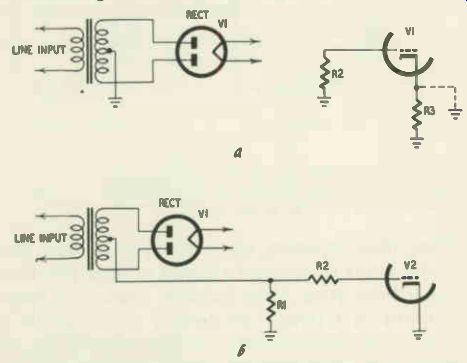
Figs. 803-a, -b. One method for eliminating hum caused by heater-to-cathode
leakage is to short the cathode resistor (upper drawing) and replace it with
a bias network connected to the power supply (lower drawing).
... be effected by connecting the filament to a dc voltage that is negative with respect to the cathode. Cathode-to-heater emission is not common-certainly not as frequent as heater-to-cathode emission.
In either case, hum may be produced.
In the case of heater-to-cathode leakage, current flows from filament to cathode and through the impedance between cathode and ground; if this impedance is large and not adequately bypassed by a capacitor, a hum voltage will be developed in the cathode circuit. Since the hum signal affects the grid-to-cathode voltage, it will be passed through the tube unless the latter's load impedance is so small at low frequencies that the hum is severely attenuated.
Heater-to-cathode leakage in an audio amplifier-particularly the first audio amplifier-is likely to produce the greatest amount of hum.
Sometimes the effect of heater-to-cathode emission becomes audible because of a loss in capacitance of a cathode bypass capacitor.
If a large cathode bypass capacitor in an audio amplifier stage open circuits, for example, a substantial hum voltage may be built up across the cathode resistor of this stage. Replacement of the capacitor, necessary in any case to restore volume to normal, may by pass and eliminate the hum, making a tube replacement un necessary. Another way to eliminate hum due to heater-to-cathode ...

Figs. 804-a, b. Cathode-to-heater leakage in a discriminator.
... tube (drawing at the left) can be eliminated by making circuit changes (drawing at the right). leakage (other than replacing the tube) is to ground the cathode of the tube and apply the correct amount of negative dc voltage to the grid (as a bias) from some suitable source in the set. The center-tap circuit of a power-transformer secondary in an ac receiver may provide such a source, as illustrated in Fig. 803.
The effects of heater-to-cathode leakage in rf and if stages may sometimes be eliminated by using a larger value of cathode bypass capacitance in these stages (saving the cost of a tube replacement). Hum generated by heater-to-cathode leakage may prove trouble some in some discriminator stages used in FM radios, particularly if a miniature tube (in which the spacing between cathode and heater is very small) is used in this stage. The trouble may be eliminated either by a suitable tube substitution or by making the normally grounded cathode positive with respect to the filament (the other cathode is already positive). This may be readily achieved by inserting a resistor of about 10,000 ohms, bypassed by a .01-uf capacitor, in series with R2 (Figs. 804-a,-b). Now add series resistor Rx as indicated in Fig. 804-b. The value of the resistor should be such that 10 to 15 volts is developed across R3, the 10,000-ohm resistor. When the B voltage is 250, use of a resistor of about 160,000 ohms for Rx will provide the correct voltage drop across R3.
The presence of an excessive filament voltage may be the cause of an undue amount of heater-to-cathode leakage. Don't neglect to check filament voltages when likelier sources of hum have been checked and found blameless.

Figs. 805-a, -b. Improper wiring of the series filaments in an ac-dc receiver
can be a source of hum.
A rather hard-to-detect source of hum may be introduced when a technician improperly wires a filament line in an ac-dc set. In one receiver the filament of a 12AV6 detector-amplifier was positioned at too high a point in the filament string (Figs. 805-a,-b). The above-normal ac voltage present between heater and cathode of the 12AV6 produced a greater-than-usual amount of leakage between the two elements; since hum in the first audio amplifier receives more amplification than hum developed in any other stage, audio trouble resulted.
The service technician should know the correct lineup of tube filaments in ac-dc sets to recognize similar trouble. The first audio amplifier (and detector) should be at the bottom of the string or nearest ground (Fig. 805-a); next to this filament should be that of the converter (since this tube is very prone to modulation hum); then the if amplifier, power amplifier and rectifier filaments, in that order.
Modulation hum
Hum that manifests itself only when a station is tuned in is known as modulation hum. It may be caused by heater-to-cathode leakage in an oscillator, rf or if tube. When the trouble exists in the oscillator, amplitude or frequency modulation of the oscillator by the hum signal is the means by which the hum secures passage through the rf and if sections of the receiver. Heater-to-cathode leakage in an rf or if amplifier tube will become audible if the tube is working along a nonlinear portion of its e_c –i_b characteristic (a mixing or heterodyning action takes place in a tube that presents a nonlinear impedance to incoming signals). Hum due to cathode-to-heater short A direct short between cathode and heater may be the cause of hum. The short (as well as the symptom) may be continuous or intermittent. The cathode resistor of the stage affected will probably overheat when trouble is present; this should provide a clue to the source of the trouble. The reason for the overheating lies in the fact that the grid is made substantially positive with respect to the cathode during the negative phase of the hum cycle ( negative voltage at the cathode is the same as a positive voltage at the grid). Plate current flow in this interval is therefore high, causing the cathode resistor's wattage rating to be exceeded. In many instances, the resistor will smoke under such circumstances.
A cathode-to-heater short in any tube can produce audible hum.
If the short is in an rf or if tube, the large-amplitude hum may force its way through the low-impedance tuned stages (low at 60 cycles, that is) by sheer brute force-i.e., it will not have to modulate the signal to be audible. In other instances it will manifest itself as modulation hum.
Filament-to-grid coupling
A certain amount of capacitive coupling is present between the filament and grid of a tube, causing some hum voltage to be transferred from the heater to the grid. The filament-to-grid capacitance and the grid resistance form a voltage divider in this case (Fig. 806); the larger the grid resistance, the greater the hum voltage that will be developed across it. Normally, so little hum actually appears across the grid resistor (due to the small capacitance and large reactance present between filament and grid) that filament to-grid coupling is unimportant. When the grid resistance of a first audio amplifier in a high-gain audio amplifier section has increased very considerably, however, hum developed across the grid resistance as a result of the tube action just described may become excessive and therefore audible. Reduction of the grid resistance to a normal value, rather than a tube substitution, is the proper solution in such cases.
Tube shields and hum
When a tube is near a strong magnetic field (such as that pres ent around a power transformer), hum may be induced into the tube unless it (or the transformer) is properly shielded. When hum is present, a quick preliminary inspection will determine whether any tube shield is missing or improperly mounted. Look for a lonesome shield contact spring-i.e., one which has no shield to make contact with-at the tops of the tube sockets; or look for a shield which is not properly grounded. Sometimes substitution of a glass for a metal type tube is responsible for hum. Putting a grounded shield around the tube will eliminate the trouble; or else the metal type originally present may be used to replace the glass tube.
Lead-dress hum Improper placement of a grid lead (in cases where a tube grid terminates in an external cap) can produce hum. Such leads should be dressed away from other grid leads as well as the power transformer (if one is present). Improper dress of pilot-light leads may also be responsible for hum.

Fig. 806. Filament-to-grid capacitance can result in hum modulation of the
control grid.
Socket trouble
Infrequently, leakage from filament to grid or filament to plate may occur through the socket and produce hum. When other possible sources of hum have been eliminated, the socket of the suspect stage may be replaced as a test as well as a remedy for this kind of trouble. Leakage between a pilot-light socket and chassis when a "floating" ground is present (i.e., chassis is not ground) may also be the cause of hum.
Obscure causes of hum
Leakage may occur from plate or filament pins of a rectifier to unused pins on the tube. If these unused pins go to socket contacts that are employed as tie points, hum (as well as other troubles) may be introduced. A scope test will reveal the presence of hum voltage at such a socket contact. The remedy lies in clipping off the troublesome unused tube pin, or else using another socket con tact as a terminal point. The tube may also be changed, of course.
In a pentode tube which has a low input signal applied to it, the magnetic field surrounding the filament affects the division of current between plate and screen. This effect is normally negligible. When a change in grid or screen voltage has taken place, however, the hum produced by this effect may become audible.
Check the tube element voltages when such trouble is suspected.
Tube-caused buzz
A detect in a 50L6-GT type tube may cause a loud buzz to be audible. A clue to the source of the trouble may be obtained by placing a finger on top of the tube. The buzz will either increase or decrease in volume (depending on the polarity of the line plug in the outlet) if the 50L6-GT is causing it. When a permanent magnet is placed at the top of the tube, the buzz will disappear, suggesting that Barkhausen oscillation is responsible for it. Re placement of the tube will eliminate the trouble. A temporary- or permanent-repair may also be affected by taping a magnet from a small PM speaker on top of the tube.
Oscillation
When energy is fed back from plate to grid within a tube or from grid to some preceding stage, oscillation may occur. (Oscillation involving components other than tubes may also be generated in other ways, of course.) Whistles, howls, motorboating or other noises may be heard when oscillation is present. Tubes are not usually the cause of such trouble, but they can be. Shield and lead-dress trouble may also be the causes of oscillation.
Converter tubes may be the source of motorboating, particularly at low-frequency dial settings. The 12SA7, for instance, has produced symptoms of this kind in some ac-dc sets. It is worth noting that a tube which causes motor-boating in one set may work fine in others and will also check normal in a tube tester.
Some brands of if tubes may, when inserted into certain receivers, cause whistles to be heard in conjunction with the desired sound. Defects in such a tube can also cause an oscillation that manifests itself as a loud, continuous noise. The desired sound will be completely drowned out. The defective tube will probably test satisfactorily in a tube checker.
Even a new if tube may be the source of such oscillation. When an oscillating if tube is replaced and symptoms persist, the service technician is likely to look elsewhere for the trouble and keep looking elsewhere, unless he realizes that new tubes should not be exempt from suspicion.
A loose if tube shield or one that makes imperfect contact with the chassis is not infrequently a source of oscillation that results in whistles, howl or hum. The trouble may be continuous or intermittent. Check the ground contacts of any shields present when such symptoms are heard. Short a suspect shield to ground and note whether symptoms clear up to make absolutely sure that its contact is not imperfect.
In some cases where a metal if tube is used, trouble at the socket may nullify the shielding effect of the metal envelope of the tube. There may be an open at the socket contact connecting the tube shield to the chassis. To check for such a defect when the chassis is in its cabinet, scrape off some of the paint on the tube envelope and connect a wire between the metal envelope and chassis. If the oscillation stops, such an open is probably causing it.
In some cases, many of the howls and squeals that affect broad cast ac-dc sets may be eliminated by substituting a 1N34 crystal in place of the diode of the duo-diode-triode detector generally employed. The squeals are due to the presence of if and audio signals in the same tube; separation of the signals eliminates the undesired coupling effects responsible for the squeal.
Microphonic tubes
A microphonic tube is one that generates undesired electrical signals when it is subjected to mechanical vibration. The vibration causes movement of the electrodes in the tube with respect to each other. The characteristics of the tube vary in consequence, producing spurious signals or noise.
All amplifier tubes are microphonic to a certain extent; in some, however, the defect is great enough to produce very noticeable symptoms. The troublesome tube must be located and re placed.
Tube tapping is perhaps the best way to locate a microphonic.
Tap each tube gently with the wooden base of a screwdriver.
When a microphonic noise is heard only when . a certain tube is tapped, that tube should be replaced and results noted. If the tubes are tapped too hard, not only may damage be done to them, but the entire purpose of the tests will be defeated. Noise will be heard even when good tubes are tapped because the good tubes will transfer vibration through the chassis to the bad one. Some times, though, tapping tests will be of no help in locating a microphonic tube.
The converter (more specifically, the oscillator) is, incidentally, the stage most likely to be the source of audible microphonic symptoms. This is true because the oscillator tuned circuit is resonant to-only a single frequency at any tuning capacitor setting.
It is so sharply tuned that the slight shift in interelectrode capacitances produced by a tube microphonic produces a large percent age of frequency change. Rf and if tuned circuits, on the other hand, are quite broad by comparison. A shift in interelectrode capacitance of an rf amplifier or if tube will, therefore, produce a much smaller percentage of frequency change.
Frequency changes in plate currents caused by microphonics are detected in the if amplifiers by the process of slope detection and amplitude-modulate the if signal. They become audible after demodulation in the second detector as howls, rattles or other noise.
If the service technician is uncertain whether a microphonic condition is present, the following procedure will help him make up his mind. Detune the receiver slightly from its station setting.
If the noise increases in volume, a microphonic is probably the cause of it. Detuning shifts the oscillator frequency and changes the frequency of the carrier slightly. As a result, the if carrier now falls lower down on the slope of the if selectivity curve. A greater amount of slope length now becomes available and the micro phonic signal produced by slope detection is therefore increased in amplitude.
Variations in heater-to-cathode capacitances would tend to cause microphonics in the oscillator of FM sets if counter measures were not taken. Consider an FM pentagrid converter, such as a 6BE6, for instance. The cathode connects to a tap on the oscillator coil in the Hartley circuit commonly used in such converter circuits.
The heater-to-cathode capacitance is therefore part of the oscillator tank circuit.
If vibration causes the heater to move in the cathode sleeve at an audio-frequency rate, the heater-to-cathode capacitance will vary at the same rate. The oscillator frequency of operation will therefore vary at this rate. This undesired frequency modulation of the oscillator is detected along with desired FM signal and be comes audible as a howl. Connection of the cathode to the heater, either directly or through a capacitor, and the insertion of rf chokes in one or both legs or the heater (Figs. 807-a,-b) are often used to minimize such microphonics.
These data are presented so that circuit trouble that makes tube microphonics excessively noticeable will not be blamed on the oscillator tube. The circuit trouble referred to is a defect in, or omission of, a heater coil, or an open-circuiting of the cathode connection to heater.
Noisy tubes
Tube defects are common sources of noise other than micro phonics. Other component defects may, of course, also produce noise. The erratic and intermittent nature of the noise symptoms often produced by tubes can make the localization of the trouble rather difficult.
Some noisy tubes are fairly simple to locate. If tapping a certain tube produces noise, whereas tapping the other tubes does not, chances are the first tube is the source of the trouble. To verify this, substitute a new tube, then try the tapping tests once more.
When a grid cap is present on a tube, the connection to the cap sometimes becomes loose, introducing noise. Tapping the suspect cap from various angles and noting whether noise is produced or increased will help localize this source of trouble. If a loose grid cap seems to be present, reheat the connection by holding a soldering iron for a short while to the cap.

Figs. 807-a, -b. Filament-to-cathode capacitance (drawing at the left) can
result in howling. One technique for minimizing this trouble is the use of
an rf choke (modified circuit shown at the right). Sometimes the glass envelope
of a tube becomes loose. Normally, this envelope is cemented to the base.
A loose envelope will readily vibrate, causing noise. Try moving the envelopes
of the various tubes (avoiding a burn, if the set is on, by using a tube puller
or equivalent protection). If a loose envelope is found, pour a little radio
cement between the glass envelope and the tube base.
One of the leads from the tube elements to the base prongs sometimes loosens inside a prong. Noise, as well as other symptoms may result. Inspect the base prongs of the suspected tube to determine if trouble lies here. If a connection looks in the least suspicious, apply a hot soldering iron to the prong to re-form the connection between prong and lead. In some cases, a bit of solder may be added to speed the operation. Excess solder may be removed by holding the soldering iron to the prong and scraping off the undesired solder.
In many instances, a tube will not become noisy until it has heated sufficiently. To find the culprit in such cases, let the receiver operate for an hour or more. Then try the tapping tests previously described.
Sometimes an intermittently noisy tube will stay on its best behavior indefinitely when the chassis is out of the cabinet. The additional ventilation present may keep the intermittent from be coming active. Try to duplicate the conditions under which the set usually functions--i.e., either put it back into its cabinet, cover it with a box or expose it to the rays of a hot lamp for a while.
If several tubes produce noise when they are tapped, strike the tubes with increasing gentleness to prevent the non-guilty ones from acting up. If isolation of the bad tube cannot be achieved in this way, disconnect the external antenna (if one is used) and/or short out the built-in antenna (when present). Now turn up the volume control, and repeat the localization test just described.
If this method also proves unsuccessful, set the volume control at minimum. If noise--even faint noise--can still be produced by tube tapping, the faulty tube is most likely in the audio section.
This deduction is logical because the output of the rf/if stages is zero at minimum volume-control setting, therefore nothing- neither signal nor noise-can come from these stages under such circumstances.
If noise that is obtained with the volume control setting high disappears and cannot be reintroduced even faintly with the volume-control setting at zero, the trouble probably lies in the rf/if section.
To localize a noisy tube in an audio section of a straight ac set, proceed as follows: Remove the tube preceding the power amplifier, then tap the power amplifier (or amplifiers). If noise is still faintly audible (you'll have to put your ear close to the speaker to determine this), the tube that produces the noise when tapped is probably to blame. Substitution of a new tube and retest will verify this.
If the noise is no longer heard when the tube preceding the power amplifier (s) is withdrawn, replace the tube and withdraw the one just before it. Now repeat the test procedure. Proceed backward in this way until a tube is found which produces noise when tapped. More specifically: the first tube whose removal causes disappearance of the noise symptoms is the defective one (assuming no circuit component is responsible for the trouble). The procedure is the same for localizing a faulty tube in the rf/if stages except that you begin with the last tube in this section.
If the set being serviced is an ac-dc type, a noisy tube in the audio section may be located as follows: Remove the detector tube from its socket while the set is in operation. There will be a brief period of time immediately following during which the filaments of the tubes remain hot and their cathodes continue to emit. Tap the power amplifier and rectifier tubes during this short interval (we are considering the rectifier as part of the audio amplifier section). If noise is faintly heard, the detector is not guilty whereas one of the tubes that has been tapped is responsible. If noise is not heard, the detector-or a tube preceding it-may be causing it.
You'll have to be real quick to make such a test.
Let's assume noise is heard when the test just described is made.
How can you localize it to one of the two tubes that may be producing it? Substitution of one tube, then rechecking, offers the simplest isolation test.
In the case of noisy tubes in the rf/if section, the same procedure may be used with the exception that you start with the last tube in this section.
Rectifiers in ac-dc sets may radiate noise in some cases. When a tube element in the rectifier becomes loose, rf interference can be generated. Radiation of this interference to the loop antenna causes the noise to get into the receiver. The remedy lies in either replacing the tube or putting a shield over it and then grounding the shield to chassis.
Another unsuspected source of noise can be the tuning-eye tube.
Loose elements can produce noise that is applied to other tubes via the avc line.
In some older-make radio sets, intermittent and hard-to-locate noise that is intensified when the converter is tapped is often due to a defective wafer socket in this stage. The socket, held together by rivets, becomes conductive with age, introducing a varying low impedance path to ground from the oscillator grid-or some other element-through the rivets.
Intermittent noise may be due to loose or imperfect contact between a tube and its socket. Wiggling the tubes in their sockets is one way of localizing such trouble. Try to find a tube which, when wiggled, will produce this noise when other tubes will not.
The associated socket is probably at fault in this case (a component connected to the socket can also be the source of trouble). If some doubt is present whether the socket or the tube itself is causing the noise, hold the tube firmly in place with one hand while tapping it with a screwdriver held in the other. If the tube is defective, the noise will still be produced; if the source of trouble lies in the socket, noise will no longer be audible.
Noisy pilot lamps and sockets are sources of noise that are sometimes overlooked. In certain cases, a defective pilot lamp will flicker abnormally when tapped; in most cases, it probably won't.
The pilot lamp may be loose in its socket, or the socket contacts may be dirty or the lamp itself may have a defect in it. Noise produced by a defective pilot light may sometimes take the form of buzz.
Loose tube shields may be the cause of noise. Tapping tests and visual inspection will readily locate such a source of trouble.
Tube troubles in portable radios
Tubes used in portable sets (except for the tube rectifier that is sometimes present) have low-voltage filament cathodes. Battery operation demands such a design. The filaments are generally connected in one of the ways indicated in Figs. 808-a,-b,-c.
Plate and screen currents pass through the filaments. Proper bias is obtained by returning the grid resistor of a tube to one side of the filament. We mention these things because they have a bearing on the servicing of tube troubles.
Avoiding tube damage I he filament voltage of portable type tubes is either 1.4 or 2.8.
Any of a number of defects can cause such small voltage ratings to be exceeded; one or more tubes are likely to "blow" in con sequence. To avoid such damage, the technician must know how and why it can take place. The need for such knowledge is enhanced by the fact that portable type tubes used in older-make portable sets are more expensive than those used in standard AC DC sets.
Tubes should never be removed from or restored to their sockets when a battery-electric portable is being operated from the power line. Burnout of one or more tubes is likely in certain types of filament circuit if this precaution is ignored (or if a tube is loose in its socket).
Assume that the filament circuit illustrated in Fig. 809 is present. If VI is withdrawn while the set is in operation, the large charge present across filter capacitor C 1 (between cathode of the ...

Figs. 808-a, -b, -c. Filament connections in portable radio receivers are
shown in these three drawings.
... rectifier and ground) cannot leak off through the tube filaments to ground because the filament path has been interrupted. Suppose this charge produces a voltage between cathode and ground of 130. This same voltage will appear across C2 and C3 since no current flows through R1 and R2 and no voltage is therefore lost. When V1 is replaced by a new tube, 130 volts will be im posed on the four tubes in series, instead of the 7 volts normally present. The burnout of one or more tubes is inevitable under such circumstances. A burnout due to such a chain of events is also possible when a tube is replaced. To make sure a replacement tube is not damaged, short the filter capacitors to ground (with the power off, of course) before the new tube is inserted into the socket. In many instances, the presence of resistors in the filament circuits "bleeds" the filter capacitors, preventing such damage when a tube is withdrawn.

Fig. 809. If V1 is removed while the set is turned on and is then replaced
the voltage across C3 (about 130 volts) will be shunted across the filaments
of the four tubes. The filaments of one or more tubes will be destroyed.
Any component defect that causes the filament voltages of the tubes to rise considerably can result in the burnout of one or more tubes. When a replacement tube "blows" as soon as it is inserted, a check for such component trouble is definitely in order. Possible sources of filament blowouts include the following:
1. Decrease in the value of the dropping resistor between rectifier cathode and filaments.
2. Change in the value of a filament shunting resistor. These resistors shunt enough current from the filament circuits to pre vent plate and screen currents from causing normal filament voltages to be exceeded; their normal value is such that the filament voltages are correct. If a filament-shunting resistor increases in value, it will pass less current, permitting more current to flow through one or more of the tube filaments. Excessive filament voltage results. Such trouble is particularly likely in the case of a double filament type output tube. Check the voltages developed across each section of the double filament, making sure they are normal and equal, if premature blowouts of the tube are being investigated.
3. Short between filament and some other tube electrode. Such a short is likely to blow tube replacements if the shorted tube is permitted to remain in the circuit. To avoid this possibility, check all tubes for short circuits, before replacing one of them.
4. Open in the common negative of a filter capacitor at the point indicated in Fig. 810. While such trouble is not common, it can and does occur. The filtering action is partially impaired whenever such a defect develops. The ripple voltage that is now applied to the filaments (in addition to the normal voltage) may damage one or more of them if the set is left on for a considerable length of time. Checking the ripple voltage across the filaments will indicate whether such trouble should be investigated. Normally, the ripple voltage measured will be zero or close to zero. A scope should preferably be used for such a measurement since it is insensitive to the dc voltage present.
5. Accidental brushing of the "hot" pigtail of a test capacitor, that has been used to bridge a power-supply filter capacitor, against a filament circuit point. Many novices-as well as some experienced technicians-have gone through this rather depressing experience.
Intermittent operation and fading
One of the most characteristic troubles in portable receivers is intermittent operation. The set fades out after playing a while in some cases; in others reception occurs over approximately half the dial only.

Fig. 810. Increased ripple voltage applied to the filaments (when the filter
is open) can result in damage to the tubes.
The trouble in such cases is generally an inoperative or partially operative converter tube (such as the 1R5, 1A7-GT and 1LA6). It must be stressed, however, that this does not necessarily mean that the tube itself is defective--in many cases, the trouble lies, rather, in the insufficient filament voltage that is fed to the tube. A decrease of as little as 0.2 volt may cause the converter to become partly or wholly inoperative if its transconductance isn't high.
A check to determine whether this stage is the source of trouble can be made by connecting an external antenna or a long piece of wire to the grid of the tube. If reception is restored or the background noise level increases considerably, the converter stage is very probably at fault.
Before replacing a fading converter, check its filament voltage.
This is a must, not only to save the cost of an unnecessary tube replacement, but to insure against a callback or a premature service call for the same complaint.
When the filament voltages of all the 1.4- or 2.8-volt tubes are below normal with the line voltage at 117, the following possible causes of trouble should be investigated:
1. Weak rectifier (selenium or tube).
2. Loss of capacitance in the filter capacitors.
3. Increase in the value of the dropping resistor between rectifier cathode and the filament circuit.
4. In the case of a circuit like the one shown in Fig. 808-c, where a combination rectifier-power amplifier tube is present and the amplifier section feeds the filaments of the 1.4- or 2.8-volt tubes, a loss of emission in this amplifier section may be responsible.
5. When the filament voltage of the converter alone is too low, a reduction in the tube's filament resistance may be present.
Resistance-check the tube filament to verify this possibility. The normal resistance of a 1.4-volt tube filament is 28 ohms. It is advisable to use a resistance of 30 ohms or more in series with the ohmmeter lead (and subtract this value from the total reading) when making such a resistance check, to avoid the possibility of excessive current from the ohmmeter damaging the tube filament.
When the filament voltage is normal, and fading occurs, a new converter tube should be substituted and results noted.
It is worth noting that in some receivers, 1.4-volt tubes are placed in a circuit where they will be fed only 1.2 volts. This voltage is "normal" in such a case.
There are many cases where fading occurs only at reduced line voltages. To determine whether low line voltage at the customer's home is responsible for the symptoms or whether the trouble lies in the receiver, an autotransformer that permits the line voltage applied to the set under test to be suitably varied is necessary. If the set works for 5 minutes or longer at a line voltage of 105 or higher, a tube or component trouble in the set (rather than the line voltage) is probably to blame and should be checked. The B voltage may, for instance, drop disproportionately in the presence of reduced line voltage due to impaired efficiency of the rectifier or the power supply filter capacitance may be insufficient. The value of the dropping resistor between rectifier cathode and filaments may be too high, etc.
Fading in sets using miniature tubes is sometimes the result of poor contact of tube prongs and socket, due to a bent prong or loose socket. Socket contacts may be tightened with a scribe; bent prongs may be straightened with a pair of long-nose pliers.
Restoring converters to normal operation
Suggestions have already been made for restoring the converter tube to normal operation when its filament voltage is below normal, when the 1.4-2.8-volt tube filaments are fed from the rectifier cathode through a dropping resistor. When the filaments derive their current from the amplifier section of an amplifier- rectifier dual-purpose tube and the amplifier section of the tube has lost some of its emission, the following remedy may be applied to boost the filament voltages of the 1.4-2.8 volt tubes. A 10-watt wirewound resistor of about 5,000 to 7,000 ohms may be connected between screen and cathode of the amplifier section (of the amplifier-rectifier tube). Use a value that will raise the filament voltages to the correct level and no higher. A sticker should be pasted near the amplifier-rectifier tube, advising any service technician who may subsequently work on the set to remove the resistor if the dual purpose tube is replaced.
Fading converters, regardless of the kind of filament-feed circuit employed, can often be restored to normal operation by reducing the screen voltage of the converter tube. When the screen dropping resistor is some value between 10,000 and 50,000 ohms, for instance, substitution of a resistance of 100,000 ohms will often do the trick.
Sometimes a non-miniature converter tube that would otherwise have to be replaced may be given a new lease on life if its base is heated for a few minutes with a soldering iron or a small alcohol torch.
In-operation
When the rectifier is a tube and it doesn't light (on electric operation), a resistance check of its filaments will quickly reveal whether the latter has open-circuited. When the filaments of the 1.4-2.8-volt tubes don't glow normally (on either battery or electric operation), one of the tube filaments is probably open.
(Close visual inspection is needed to check the filament lighting.) In some sets, the pilot light is in series with the 1.4-2.8-volt tube filaments; a burned-out pilot lamp will open-circuit the heaters of these tubes and keep the set from operating.
Distortion
Power amplifier tubes-such as the 3V4, 3Q5-GT, etc.-are frequent sources of distortion. A distorting tube will often be given a clean bill of health in a tube tester; substitution is, therefore, the best test for such trouble.
In some instances an improper tube substitution may be the source of distortion.
A defective power amplifier in a rectifier-amplifier tube (such as a 117L7/M7-GT, etc.) is generally responsible for a "creeping" (slowly-developing) distortion.
Low volume
Loss of emission in any tube will reduce volume. An unusual and unexpected source of lowered volume may be the closeness of a miniature output tube (such as a 1S4) to the speaker magnet.
The magnetic lines of force emanating from the speaker magnet affect the space charge in the tube and reduce its amplification. The trouble may arise when the tube is slightly bent in the direction of the speaker. To eliminate the condition, straighten any bent tube prongs. A piece of felt placed between tube and speaker will be helpful in keeping the tube upright and at maximum separation from the speaker.
Miscellaneous symptoms
When symptoms of trouble are present at a high setting of the volume control but not a low one, and vice versa, a faulty detector tube is often to blame. "Quavery" reception that sounds like a grossly exaggerated tremolo effect may be produced by a defective if amplifier or converter tube. Noisy reception is not infrequently due to dirty or corroded prongs on miniature tubes. The prongs may be cleaned by rotating the jaws of a pair of long-nose pliers around each prong, at the same time moving the pliers down along its length. The pliers should have serrated jaws. Squeals and no reception may be due to the absence or improper grounding of a shield on an if tube (such as a 1N5-GT). Difficulties in tuning may stem, in some cases, from a gassy power amplifier.