THE installation of electron tubes requires care if reliable performance is to be obtained from the associated circuits. Installation suggestions and precautions which are generally common to all types of tubes are covered in this section. Additional pertinent information is given under each tube type and in the Circuits section.
Filament and Heater Power Supply
The design of electron tubes allows for some variation in the voltage and current supplied to the filament or heater, but most satisfactory results are obtained from operation at the rated values. When the voltage is low, the temperature of the cathode is below normal, with the result that electron emission is limited. The limited emission may cause unsatisfactory operation and reduced tube life. On the other hand, high heater voltage may cause rapid evaporation of cathode material and shorten tube life.
To insure proper tube operation, it is important that the filament or heater voltage be checked at the socket terminals by means of a high-resistance volt meter while the equipment is in operation. In the case of series operation of heaters or filaments, correct adjustment can be checked by means of an ammeter in the heater or filament circuit.
The filament or heater voltage supply may be a direct-current source (a battery or a dc power line) or an alternating-current power line, depending on the type of service and type of tube.
Ordinarily, a step-down transformer is used with an ac supply to provide the proper filament or heater voltage. Receivers intended for operation on both dc and ac power lines have the heaters connected in series with a suitable resistor and supplied directly from the power line.
Mobile and marine receivers have the heaters of the tubes connected directly across the battery supply.
Parallel heater operation usually requires a step-down transformer to reduce the 120 Vac line voltage to typically 6.3 Vac. Care must be taken to prevent excessive voltage drop in the heater circuit wiring which would result in incorrect voltage at the tube terminals.
Series heater operation eliminates the need for a step-down transformer and is economical when a number of tubes rated at the same heater current have a total heater voltage drop which adds up to an available supply voltage. A voltage-dropping resistor in series with the heaters and the supply line is usually required. This resistance should be of such value that for normal line voltage the tubes will operate at their rated heater current. The resistor value is calculated by the following formula.
Required resistance (ohms) = supply volts - total rated volts of tubes rated amperes of tubes
The power dissipation of the resistor (in watts) is equal to the voltage drop of the resistor multiplied by the series string current in amperes.
A resistor having a wattage rating well in excess of this value should be chosen.
A convenient means exists for obtaining a heater supply voltage drop without the disadvantage of a power dissipating resistor. A diode in series with the 120 Vac line provides a half wave rectified sine wave of 84 V (\/2 x RMS input). The diode polarity should be such as to operate the heaters negative. (See heater-cathode voltage below.) In TV receivers designed for instant-on operation such a series-connected diode can be used for stand-by operation (70% of rated heater voltage) of a 120 Vac series string.
Heater-Cathode Voltage
When the series-heater connection is used in equipment, it is advisable to arrange the heaters in the circuit so that tubes most sensitive to hum disturbances are at or near ground potential of the circuit. This arrangement reduces the amount of AC heater cathode voltage of these tubes and minimizes hum interference. Other tubes operated with grounded cathode, such as horizontal deflection amplifiers or tube insulated for high heater cathode voltage, such as damper, are more immune to heater-cathode leakage.
Typical orders of series-string connections, by tube function, are shown below.
Heater-type tubes may produce hum as a result of conduction between heater and cathode or between heater and control grid, or by modulation of the electron stream by the alternating magnetic field surrounding the heater.
When a large resistor is used between heater and cathode (as in series-connected heater strings), or when one side of the heater is grounded, even a minute pulsating leakage current between heater and cathode can develop a small voltage across the cathode-circuit impedance and cause objectionable hum. The use of a large cathode bypass capacitor is recommended to minimize this source of hum.
Much lower hum levels can be achieved when heaters are connected in parallel systems in which the center-tap of the heater supply is grounded or, preferably, connected to a positive bias source of 15 to 80 volts dc to reduce the flow of alternating current. The heater leads of the tubes should be twisted and kept away from high-impedance circuits.
The balanced ac supply provides almost complete cancellation of the alternating-current components.
The balanced arrangement described above also minimizes heater grid hum. High grid-circuit impedances should be avoided, if possible. High heater voltages should also be avoided because heater-cathode hum rises sharply when the heater voltage is increased above the published value.
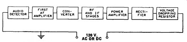
Fig. 112--Order of series heater-string connection, by tube function,
to minimize hum in a radio receiver.
Fig. 112B--Order of series healer-string connection, by tube function, to minimize hum in a TV receiver.
Certain tube types are designed especially to minimize hum in high quality, high-fidelity audio equipment.
Examples are the 5879, 7025, and 7199.
Plate Voltage Supply
The plate voltage for electron tubes is obtained from batteries, rectifiers, direct-current power lines, and small local generators. The maximum plate voltage value for any tube type should not be exceeded if most satisfactory performance is to be obtained. Plate voltage should not be applied to a tube unless the corresponding recommended voltage is also supplied to the grid.
It is recommended that the primary circuit of the power transformer be fused to protect the rectifier tube(s), the power transformer, filter capacitor, and chokes in case a rectifier tube fails.
Grid Voltage Supply
The recommended grid voltages for different operating conditions have been carefully determined to give the most satisfactory performance. Grid voltage may be obtained from a fixed source such as a separate C-battery or a tap on the voltage divider of the high-voltage dc supply, from the voltage drop across a resistor in the cathode circuit, or from the voltage drop across a resistor in the grid circuit. The first method is called "fixed bias"; the second is called "cathode bias" or "self bias"; the third is called "grid-resistor bias" and is some times incorrectly referred to in receiving-tube practice as "zero-bias operation." In any case, the object is to make the grid negative with respect to the cathode by the specified voltage. When a C-battery is used, the negative terminal is connected to the grid return and the positive terminal is connected to the negative filament socket terminal, or to the cathode terminal if the tube is of the heater-cathode type. If the filament is supplied with alternating current, this connection is usually made to the center-tap of a low resistance (20 to 50 ohms) shunted across the filament terminals. This method reduces hum disturbances caused by the ac supply. If bias voltages are obtained from the voltage divider of a high-voltage dc supply, the grid return is connected to a more negative tap than the cathode.
The cathode-biasing method utilizes the voltage drop produced by the cathode current flowing through a resistor connected between the cathode and the negative terminal of the B-supply. (See Fig. 113.) The cathode current is, of course, equal to the plate current in the case of a triode, or to the sum of the plate and grid-No. 2 currents in the case of a tetrode, pentode, or beam power tube. Because the voltage drop along the resistance is increasingly negative with respect to the cathode, the required negative grid-bias voltage can be obtained by connecting the grid return to the negative end of the resistance.
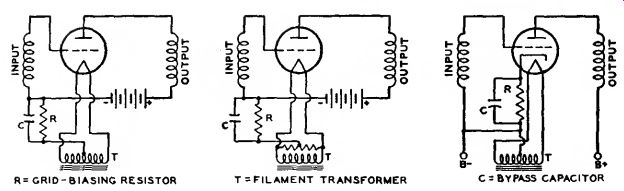
Fig. 113--Typical grid-voltage supply circuits.
The value of the resistance tor cathode-biasing a single tube can be determined from the following formula:
Resistance (ohms) =:
desired grid-bias voltage X 1U0U
... rated cathode current in milliamperes Thus, the resistance required to produce 9 volts bias for a triode which operates at 3 milliamperes plate current is 9 X 1000/3 = 3000 ohms. If the cathode current of more than one tube passes through the resistor, or if the tube or tubes employ more than three electrodes, the total current determines the size of the resistor.
Bypassing of the cathode-bias resistor depends on circuit-design requirements. In rf circuits the cathode resistor usually is bypassed. In AF circuits the use of an unbypassed resistor will reduce distortion by introducing degeneration into the circuit. However, the use of an unbypassed resistor decreases gain and power sensitivity. When by passing is used, it is important that the bypass capacitor be sufficiently large to have negligible reactance at the lowest frequency to be amplified.
In the case of power-output tubes having high transconductance, such as beam power tubes, it may be necessary to shunt the bias resistor with a small mica capacitor (approximately 0.00 1/»F) in order to prevent oscillations. The usual AF bypass may or may not be used, depending on whether or not degeneration is desired. In tubes having high values of transconductance, such as the 6BA6, 6CB6A, and 6AC7, input capacitance and input conductance change appreciably with plate current.
When such a tube having a separate suppressor-grid connection is used as an rf amplifier, these changes may be minimized by leaving a certain portion of the cathode-bias resistor unbypassed. In order to minimize feedback when this method is used, the external grid-No. 1 to-plate (wiring) capacitances should be kept to a minimum, the grid No. 2 should be bypassed to ac ground, and the grid No. 3 should be connected to ac ground.
The use of a cathode resistor to obtain bias voltage is not recommended for amplifiers in which there is appreciable shift of electrode currents with the application of a signal. In such amplifiers, a separate fixed supply is recommended.
The grid-resistor biasing method is also a self-bias method because it utilizes the voltage drop across the grid resistor produced by small amounts of grid current flowing in the grid-cathode circuit. This current is due to (1) an electromotive potential difference between the materials comprising the grid and cathode and (2) grid rectification when the grid is driven positive. A large value of resistance is required in order to limit this current to a very small value and to avoid undesirable loading effects on the preceding stage.
Examples of this method of bias are given in the Circuits section. In these circuits, the audio amplifier type 1U5 or 12AV6 has a 10-megohm resistor between the grid and the negative filament or cathode to furnish the required bias, which is usually less than 1 volt.
This method of biasing is used principally in the early voltage-amplifier stages (usually employing high-mu triodes) of audio amplifier circuits, where the tube dissipation will not be excessive under zero-signal conditions.
A grid resistor is also used in many oscillator circuits for obtaining the required bias. In these circuits, the grid voltage is relatively constant and its magnitude is usually in the order of 5 volts or more. Consequently, the bias voltage is obtained only through grid rectification. A relatively low value of resistor, 0.1 megohm or less, is used. Oscillator circuits employing this method of bias are given in the Circuits section.
Grid-bias variation for the rf and if amplifier stages is a convenient and frequently used method for controlling receiver volume. The variable voltage supplied to the grid may be obtained:
(1) from a variable cathode resistor as shown in Figs. 114 and 115; (2) from a bleeder circuit by means of a potentiometer as shown in Fig. 116; or (3) from a bleeder circuit in which the bleeder current is varied by a tube used for automatic volume control.
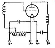
Fig. 114-Amplifier stage using a variable cathode-bias resistor for
volume control.
The latter circuit is shown in Fig 61.
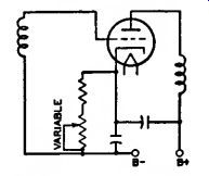
Fig. 115-Amplifier stage similar to Fig. 114 but using heater-cathode-type
tube.
In all cases it is important that the control be arranged so that at no time will the bias be less than the recommended minimum grid-bias voltage for the particular tubes used. This requirement can be met by providing a fixed stop on the potentiometer, by connecting a fixed resistance in series with the variable resistance, or by connecting a fixed cathode resistance in series with the variable resistance used for regulation. Where receiver gain is controlled by grid-bias variation, it is advisable to have the control voltages extend over a wide range in order to minimize cross-modulation and modulation-distortion. A remote-cutoff type of tube should, therefore, be used in the controlled stages.
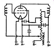
Fig. 116-Amplifier stage using a bleeder circuit and potentiometer for
volume control.
In most tubes employing a uni-potential cathode, a positive grid current begins to flow when the grid is slightly negative and increases rapidly as the grid is made more positive, as shown in Fig. 117. The value of grid voltage at which the grid-current curve intercepts the horizontal axis is determined by several different physical processes, including an electrothermal effect due to the differences in temperature and in material composition of the grid and the cathode, and by the positive grid current. For values of grid potentials which are larger than this intercept, the direction of the grid current is positive (i.e., from the cathode to the grid). At smaller values of grid potential, the direction of the grid current is negative (i.e., from the grid to the cathode).
Positive grid current consists of electrons emitted from the cathode which are intercepted by the control grid. Negative grid current, which be comes appreciable only when the grid potential is more negative than the value of the intercept, is a result of the emission of electrons from the heated control grid to the cathode, the effect of gas molecules in the tube, and the influence of leakage currents between the grid and cathode and the grid and the plate.
The value of grid potential at the intercept of the grid-current curve on the horizontal axis (often mistakenly called contact potential) may be as high as 1.5 volts. If the operating bias of the tube is less than this intercept, it is found that two effects are present.
Direct current flows in the grid circuit, and the dynamic input resistance of the tube may be relatively low. It is generally desirable to supply the tube with a value of bias sufficiently high so that the operating point of the tube is not near the value of this intercept. If the value of the operating bias is near the value of the intercept, care should be taken to avoid undesirable effects in the grid circuit due to grid current or low input resistance.
Screen-Grid Voltage Supply
The positive voltage for the screen grid (grid No. 2) of screen-grid tubes may be obtained from a tap on a voltage divider, from a potentiometer, or from a series resistor connected to a high-voltage source, depending on the particular tube type and its application.
The screen-grid voltage for tetrodes should be obtained from a voltage divider or a potentiometer rather than through a series resistor from a high voltage source because of the characteristic screen-grid current variations of tetrodes. Fig. 118 shows a tetrode with its screen-grid voltage obtained from a potentiometer.
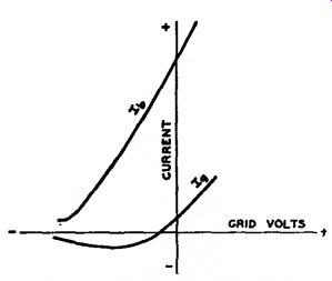
Fig. 117-Curves showing flow of positive grid current in tubes employing
uni-potential cathodes.
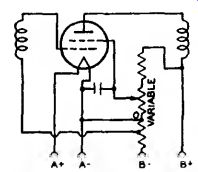
Fig. 118-Tetrode circuit in which screen grid voltage is obtained from
a potentiometer.
When pentodes or beam power tubes are operated under conditions where a large shift of plate and screen grid currents does not take place with the application of the signal, the screen grid voltage may be obtained through a series resistor from a high-voltage source. This method of supply is possible because of the high uniformity of the screen-grid current characteristic in pentodes and beam power tubes.
Because the screen-grid voltage rises with increase in bias and resulting decrease in screen-grid current, the cutoff characteristic of a pentode is extended by this method of supply.
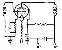
Fig. 119--Pentode circuit in which screen grid voltage is supplied through
d series resistor.
This method is sometimes used to increase the range of signals which can be handled by a pentode. When used in resistance-coupled amplifier circuits employing pentodes in combination with the cathode-biasing method, it minimizes the need for circuit adjustments. Fig. 119 shows a pentode with its screen-grid voltage supplied through a series resistor.
When power pentodes and beam power tubes are operated under conditions such that there is a large change in plate and screen-grid currents with the application of signal, the series resistor method of obtaining screen-grid voltage should not be used. A change in screen-grid current appears as a change in the voltage drop across the series resistor in the screen-grid circuit; the result is a change in the power output and an increase in distortion.
The screen-grid voltage should be obtained from a point in the plate-voltage supply filter system having the correct voltage, or from a separate source.
It is important to note that the plate voltage of tetrodes, pentodes, and beam power tubes should be applied before or simultaneously with the screen-grid voltage. Otherwise, with voltage on the screen grid only, the screen-grid current may rise high enough to cause excessive screen-grid dissipation.
Screen-grid voltage variation for the rf amplifier stages has sometimes been used for volume control in older type receivers. Reduced screen-grid voltage decreases the transconductance of the tube and results in reduced gain per stage. The voltage variation is obtained by means of a potentiometer shunted across the screen-grid voltage supply. (See Fig. 118.) When the screen grid voltage is varied, it must never exceed the rating of the tube. This requirement can be met by providing a fixed stop on the potentiometer.
Shielding
In high-frequency stages having high gain, the output circuit of each stage must be shielded from the input circuit of that stage. Each high-frequency stage also must be shielded from the other high-frequency stages.
Unless shielding is employed, undesired feedback may occur and may produce many harmful effects on receiver performance.
To prevent this feedback, it is a desirable practice to shield separately each unit of the high-frequency stages.
For instance, in a superheterodyne receiver, each if and rf coil may be mounted in a separate shield can.
Baffle plates may be mounted on the ganged tuning capacitor to shield each section of the capacitor from the other section. The oscillator coil may be especially well shielded by being mounted under the chassis.
The shielding precautions required in a receiver depend on the design of the receiver and the layout of the parts.
In all receivers having high-gain high frequency stages, it is necessary to shield separately each tube in high frequency stages. When metal tubes, and in particular the single-ended types, are used, complete shielding of each tube is provided by the metal shell which is grounded through its grounding pin at the socket terminal. The grounding connection should be short and sturdy. Many modern tubes of glass construction have internal shields, usually connected to the cathode; where present, these shields are indicated in the socket diagram.
Dress of Circuit Leads
At high frequencies such as are en countered in FM and television receivers, lead dress, that is, the location and arrangement of the leads used for connections in the receiver, is very important. Because even a short lead provides a large impedance at high frequencies, it is necessary to keep all high-frequency leads as short as possible. This precaution is especially important for ground connections and for all connections to bypass capacitors and high-frequency filter capacitors.
The ground connections of plate and screen-grid bypass capacitors of each tube should be kept short and made directly to cathode ground.
Particular care should be taken with the lead dress of the input and output circuits of high-frequency stages so that the possibility of stray coupling is minimized. Unshielded leads connected to shielded components should be dressed close to the chassis. As the frequency increases, the need for careful lead dress becomes increasingly important.
In high-gain audio amplifiers, these same precautions should be taken to minimize the possibility of self-oscillation.
Filters
Feedback effects also are caused in radio or television receivers by coupling between stages through common voltage-supply circuits. Filters find an important use in minimizing such effects.
They should be placed in voltage-supply leads to each tube in order to return the signal current through a low-impedance path direct to the tube cathode rather than by way of the voltage supply circuit. Fig. 120 illustrates several forms of filter circuits. Capacitor C forms the low-impedance path, while the choke or resistor assists in diverting the signal through the capacitor by offering a high impedance to the power supply circuit.
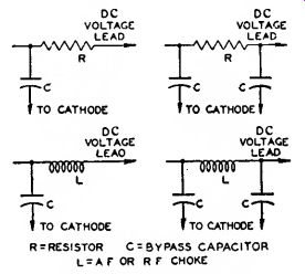
Fig. 120--Typical filler circuits.
The choice between a resistor and a choke depends chiefly upon the permissible dc voltage drop through the filter. In circuits where the current is small (a few milliamperes), resistors are practical; where the current is large or regulation important, chokes are more suitable.
The minimum practical size of the capacitors may be estimated in most cases by the following rule: The impedance of the capacitor at the lowest frequency amplified should not be more than one-fifth of the impedance of the filter choke or resistor at that frequency.
Better results will be obtained in special cases if the ratio is not more than one tenth.
Radio-frequency circuits, particularly at high frequencies, require high quality capacitors. Mica or ceramic capacitors are preferable. Where stage shields are employed, filters should be placed within the shield.
Another important application of filters is to smooth the output of a rectifier tube. (See Rectification.) A smoothing filter usually consists of capacitors and iron-core chokes. In any filter-design problem, the load impedance must be considered as an integral part of the filter because the load is an important factor in filter performance. Smoothing effect is obtained from the chokes because they are in series with the load and offer a high impedance to the ripple voltage. Smoothing effect is obtained from the capacitors because they are in parallel with the load and store energy on the voltage peaks; this energy is released on the voltage dips and serves to maintain the voltage at the load substantially constant. Smoothing filters are classified as choke-input or capacitor-input according to whether a choke or capacitor is placed next to the rectifier tube. (See Fig. 121.)
The Circuits section gives a number of examples of rectifier circuits with recommended filter constants.
If an input capacitor is used, consideration must be given to the instantaneous peak value of the ac input voltage. This peak value is about 1.4 times the rms value as measured by an ac voltmeter. Filter capacitors, therefore, especially the input capacitor, should have a rating high enough to withstand the instantaneous peak value if break down is to be avoided. When the input choke method is used, the available dc output voltage will be somewhat lower than with the input-capacitor method for a given ac plate voltage. However, improved regulation together with lower peak current will be obtained.
Mercury-vapor and gas-filled rectifier tubes occasionally produce a form of local interference in radio receivers through direct radiation or through the power line. This interference is generally identified in the receiver as a broadly tunable 120-Hz buzz (100 Hz for 50-Hz supply line, etc.).
It is usually caused by the formation of a steep wave front when plate current within the tube begins to flow on the positive half of each cycle of the ac supply voltage.
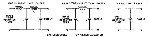
Fig. 121-Typical smoothing filters for rectifier tubes.
There are several ways of eliminating this type of interference. One is to shield the tube. Another is to insert an rf choke having an inductance of one millihenry or more between each plate and transformer winding and to connect high-voltage, rf bypass capacitors between the outside ends of the transformer winding and the center tap. (See Fig. 122.) The rf chokes should be placed within the shielding of the tube. The rf bypass capacitors should have a voltage rating high enough to withstand the peak voltage of each half of the secondary, which is approximately 1.4 times the rms value.
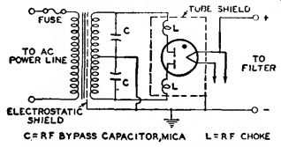
Fig. 122--Filler circuit used to eliminate interference produced by
mercury-vapor or gas-filled rectifier tubes.
Transformers having electrostatic shielding between primary and secondary are not likely to transmit rf disturbances to the line. Often the interference may be eliminated simply by making the plate leads of the rectifier extremely short. In general, the particular method of interference elimination must be selected by experiment for each installation.
Output Coupling Devices
An output-coupling device is used in the plate circuit of a power output tube to keep the comparatively high dc plate current from the winding of an electromagnetic speaker and, also, to transfer power efficiently from the output stage to a loudspeaker of either the electromagnetic or dynamic type.
Output-coupling devices are of two types, (1) choke-capacitor and (2) trans former. The choke-capacitor type includes an iron-core choke having an inductance of not less than 10 henries which is placed in series with the plate and B-supply. The choke offers a very low resistance to the dc plate current component of the signal voltage but op poses the flow of the fluctuating component. A bypass capacitor of 2 to 6 microfarads supplies a path to the speaker winding for the signal voltage.
The choke-coil output coupling device, however, is now only of historical interest.
The transformer type is constructed with two separate windings, a primary and a secondary wound on an iron core.
This construction permits designing each winding to meet the requirements of its position in the circuit. Typical arrangements of each type of coupling device are shown in Fig. 123. Examples of transformers for push-pull stages are shown in several of the circuits given in the Circuits section.
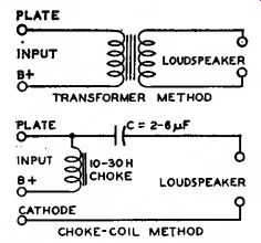
Fig. 123-Typical output-coupling devices.
High-Fidelity Systems
The results achieved from any high-fidelity amplifier system depend to a large degree upon the skill and care with which the system is constructed.
Improper placement of transformers, other components, and wiring, and at tempts to achieve excessive compact ness, can only result in instability, oscillation, hum, and other operating difficulties, as well as in damage to components by overheating. It is important, therefore, that construction of high-fidelity amplifier systems be under taken only by persons who have had some experience in the layout, mechanical construction, and wiring of audio equipment.
It is impractical to give specific construction data for various amplifiers and supplementary units because the best arrangement for each unit or combination of units will depend on the requirements of the user. It is possible, however, to list some general considerations which should be observed in the construction of any high-fidelity amplifier system.
Any amplifier having two or more stages should be constructed with a straight-line layout so that maximum separation is provided between the signal input and output circuits and terminals. Power-supply connections, particularly those carrying ac, should be isolated as far as possible from signal connections, especially from the input connection. Signal-carrying conductors, even when shielded, should not be cabled together with power-supply conductors. Internal wiring for ac-operated tube heaters, switches, pilot-light sockets, and other devices, should be twisted and placed flat against the chassis. All connections to the ground side of the circuit in each unit should be made to a common bus of heavy wire. This bus should be connected to the chassis only at the point of minimum signal voltage, i.e., at the signal-input terminal of the Unit.
All internal wiring that carries signal voltages should be as short as possible, and as far as possible above the chassis, to minimize losses at the higher audio frequencies due to stray shunt capacitance. All connections between units should be made with shielded cable having a capacitance of not more than 30 picofarads per foot, such as Alpha Type 1249 or 1704, Belden Type 8401 or 8410, or equivalent cable.
Because power amplifiers and power-supply units of high-fidelity systems normally dissipate large amounts of heat, they should be constructed and installed in such a manner as to assure adequate ventilation for the tubes and other components. A beam power tube or rectifier tube should be separated from any other tube or component on the same side of the chassis by at least 1.5 tube diameters.
Power amplifiers and power-supply units which are to be installed horizon tally (i.e., with the tubes vertical) in cabinets or on shelves should be provided with mounting feet, perforated bottom covers, and a number of small holes around each tube socket to permit relatively cool air to enter from below and provide ventilation for the under side of the chassis and tubes.
If a power amplifier, tone-control amplifier, and one or more preamplifiers are to be constructed on the same chassis, the mechanical layout should be planned so that the circuits operating at the lowest signal levels are farthest from the output stage and power supply. Amplifier units which normally operate at comparable signal levels but are not used simultaneously (such as preamplifiers for tape pickup heads and magnetic phonograph pick ups) may be installed side by side on the same chassis without danger of interaction. Units which operate simultaneously, however (such as the channels of a stereophonic system), should not be installed side by side on the same chassis without careful consideration to placement of components and wiring, and the possible use of shielding to prevent interaction.
When an amplifier, preamplifier, mixer, or other unit requiring heater power is located more than five or six feet from its power-supply unit, the heater-current conductors in the power supply cable must be large enough to assure that each tube receives its rated heater voltage. In cases where very large heater currents or very long power-supply cables are involved, it may be desirable to install a heater supply transformer on or near the amplifier unit. If such a transformer is installed on or near a preamplifier for a magnetic-tape pickup head, a magnetic phonograph pickup, or a dynamic microphone, the transformer should be completely shielded and positioned to prevent its field from inducing hum in the pickup device.
Considerations for Television Picture Tubes
Like other high-voltage devices, television picture tubes require that certain precautions be observed to minimize the possibility of failure caused by humidity, dust, and corona.
Humidity Considerations. When humidity is high, a continuous film of moisture may form on the glass bulb immediately surrounding the anode cavity cap of all-glass picture tubes or on the glass part of the envelope of metal picture tubes. This film may permit sparking to take place over the glass surface to the external conductive coating or to the metal shell. Such sparking may introduce noise into the receiver. To prevent such a possibility, the uncoated bulb surface around the cap and the glass part of the envelope of metal picture tubes should be kept clean and dry.
Dust Considerations. The accumulation of dust on the uncoated area of the bulb around the anode cap of all glass picture tubes or on the glass part of the envelope or insulating supports for metal picture tubes will decrease the insulating qualities of these parts.
The dust usually consists of fibrous materials and may contain soluble salts.
The fibers absorb and retain moisture; the soluble salts provide electrical leakage paths that increase in conductivity as the humidity increases. The resulting high leakage currents may overload the high-voltage power supply.
It is recommended, therefore, that the uncoated bulb surface of all-glass picture tubes and the coated glass surface and insulating supports for metal picture tubes be kept clean and free from dust or other contamination such as finger-prints. The frosted Filterglass faceplate of the metal picture tubes may be cleaned with a soap-less detergent, such as Dreft, then rinsed with clean water, and immediately dried.
Corona Considerations. A high voltage system may be subject to corona, especially when the humidity is high, unless suitable precautions are taken. Corona, which is an electrical discharge appearing on the surface of a conductor when the voltage gradient exceeds the breakdown value of air, causes deterioration of organic insulating materials through formation of ozone, and induces arc-over at points and sharp edges. Sharp points or other irregularities on any part of the high voltage system may increase the possibility of corona and should be avoided, In the metal-shell picture tubes, the metal lip at the maximum diameter has rounded edges to prevent corona.
Adequate spacing between the lip and any grounded element in the receiver, or between the small end of the metal shell and any grounded element, should be provided to preclude the possibility of corona. Such spacing should not be less than 1 inch of air. Similarly, an air space of 1 inch, or equivalent, should be provided around the body of the metal shell. As a further pre caution to prevent corona, the deflecting-yoke surface on the end adjacent to the shell should present a smooth electrical surface with respect to the small end of the metal shell or the anode terminal of all-glass tubes.