THE electron-tube user--service man, experimenter, or non-technical radio listener--is interested in knowing the condition of his tubes, since they govern the performance of the device in which they are used. In order to determine the condition of a tube, some method of test is necessary.
Because the operating capabilities and design features of a tube are indicated and described by its electrical characteristics, a tube is tested by measuring its characteristics and comparing them with values established as standard for that type. Tubes which read abnorm ally high with respect to the standard for the type are subject to criticism just the same as tubes which are too low.
Certain practical limitations are placed on the accuracy with which a tube test can be correlated with actual tube performance. These limitations make it impractical for the service man and dealer to employ complex and costly testing equipment having laboratory accuracy. Because the accuracy of the tube-testing device need be no greater than the accuracy of the correlation between test results and receiver performance, and since certain fundamental characteristics are virtually fixed by the manufacturing technique of leading tube manufacturers, it is possible to employ a relatively simple test in order to determine the serviceability of a tube.
In view of these factors, dealers and servicemen will find it economically expedient to obtain adequate accuracy and simplicity of operation by employing a device which indicates the status of a single characteristic. Whether the tube is satisfactory or unsatisfactory is judged from the test result of this single characteristic. Consequently, it is very desirable that the characteristic selected for the test be one which is truly representative of the tube's over-all condition.
The following information and circuits are given to describe and illustrate general theoretical and practical tube tester considerations and not to provide information on the construction of a home-made tube tester. In addition to the problem of determining what tube characteristic is most representative of performance capabilities in all types of receivers, the designer of a home-made tester faces the difficult problem of determining satisfactory limits for his particular tester. Getting information of this nature, if it is to be accurate and useful, is a big job. It requires the testing of many tubes of each type, testing of many types, and correlation of the data with performance in many kinds of equipment.
Short- Circuit Test
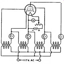
Fig. 128--Fundamental circuit of a short circuit tester.
The fundamental circuit of a short circuit tester is shown in Fig. 128. Al though this circuit is suitable for tetrodes and types having less than four electrodes, tubes of more electrodes may be tested by adding more indicator lamps to the circuit. Voltages are applied between the various electrodes with lamps in series with the electrode leads. The value of the voltages applied will depend on the type of tube being tested and its maximum ratings. Any two shorted electrodes complete a circuit and light one or more lamps. Since two electrodes may be just touching to give a high-resistance short, it is desirable that the indicating lamps operate on very low current. It is also desirable to maintain the filament or heater of the tube at its operating temperature during the short-circuit test, because short circuits in a tube may sometimes occur only when the electrodes are heated.
However, a short-circuit tester having too high a sensitivity may indicate very high-resistance shorts that do not adversely affect tube operation.
Selection of a Suitable Characteristic for Test
Some characteristics of a tube are far more important in determining its operating worth than are others. The cost of building a device to measure any one of the more important characteristics may be considerably higher than that of a device which measures a less representative characteristic. Consequently, three methods of test will be discussed, ranging from relatively simple and inexpensive equipment to more elaborate, more accurate, and more costly devices.
An emission test is perhaps the simplest method of indicating a tube's condition. (Refer to Diodes, in Electrons, Electrodes, and Electron Tubes section, for a discussion of electron emission.) Since emission falls off as the tube wears out, low emission is indicative of the end of tube serviceability. However, the emission test is subject to limitations because it tests the tube under static conditions and does not take into account the actual operation of the tube. On the one hand, coated filaments, or cathodes, often develop active spots from which the emission is so great that the relatively small grid area adjacent to these spots cannot control the electron stream.
Under these conditions, the total emission may indicate the tube to be normal although the tube is unsatisfactory. On the other hand, coated types of filaments are capable of such large emission that the tube will often operate satisfactorily after the emission has fallen far below the original value.
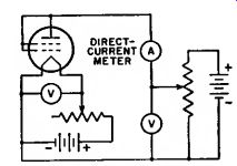
Fig. 129--Fundamental circuit of an emission tester.
Fig. 129 shows the fundamental circuit diagram for an emission test. All of the electrodes of the tube, except .the cathode, are connected to the plate. The filament, or heater, is operated at rated voltage; after the tube has reached constant temperature, a low positive voltage is applied to the plate and the electron emission is read on the meter.
Readings which are well below the average for a particular tube type indicate that the total number of available electrons has been so reduced that the tube is no longer able to function properly.
A transconductance test takes into account a fundamental operating principle of the tube. (This fact will be seen from the definition of transconductance in the Section on Electron Tube Characteristics.) It follows that transconductance tests, when properly made, permit better correlation between test results and actual performance than does a straight emission test.
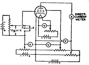
Fig. 130--Fundamental circuit of a trans conductance tester using the "grid-shift" method.
There are two forms of transconductance test which can be utilized in a tube tester. In the first form (illustrated by Fig. 130 giving a fundamental circuit with a tetrode under test), appropriate operating voltages are applied to the electrodes of the tube. A plate current depending upon the electrode voltages will then be indicated by the meter. If the bias on the grid is then shifted by the application of a different grid voltage, a new plate-current reading is obtained. The difference between the two plate-current readings is indicative of the transconductance of the tube. This method of transconductance testing is commonly called the "grid-shift" method, and depends on readings under static conditions. The fact that this form of test is made under static conditions imposes limitations not encountered in the second form of test made under dynamic conditions.
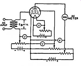
Fig. 131--Fundamental circuit of a dynamic transconductance tester.
The dynamic transconductance test illustrated in Fig. 131 gives a fundamental circuit with a tetrode under test.
This method is superior to the static transconductance test in that ac voltage is applied to the grid. Thus, the tube is tested under conditions which approximate actual operating conditions. The alternating component of the plate current is read by means of an ac ammeter of the dynamometer type. The trans conductance of the tube is equal to the ac plate current divided by the input signal voltage. If a one-volt rms signal is applied to the grid, the plate-current meter reading in milliamperes multiplied by one thousand is the value of trans conductance in micromhos.
The power-output test probably gives the best correlation between test results and actual operating performance of a tube. In the case of voltage amplifiers, the power output is indicative of the amplification and output voltages obtainable from the tube. In the case of power-output tubes, the performance of the tube is closely checked.
Consequently, although more complicated to set up, the power-output test will give closer correlation with actual performance than any other single test.
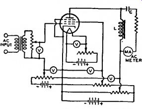
Fig. 132--Fundamental circuit of a power output tester for class A operation
of tubes.
Fig. 132 shows the fundamental circuit of a power-output test for class A operation of tubes. The diagram illustrates the method for a pentode. The ac output voltage developed across the plate-load impedance (L) is indicated by the current meter. The current meter is isolated as far as the dc plate current is concerned by the capacitor (C). The power output can be calculated from the current reading and known load resistance. In this way, it is possible to determine the operating condition of the tube quite accurately.
Fig. 133 shows the fundamental circuit of a power-output test for class ...
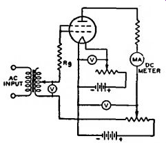
Fig. 133--Fundamental circuit of a power output tester for class B
operation of tubes.
...B operation of tubes. With ac voltage applied to the grid of the tube, the current in the plate circuit is read on a dc milliammeter. The power output of the tube is approximately equal to:
(Ib» X Rl)/0.405, where P„ is the power output in watts, 1 1, is the dc current in amperes, and Ri.
is the load resistance in ohms.
Essential Tube-Tester Requirements
1. The tester should provide for making a short-circuit test before measurement of the tube's characteristics.
2. It is important that some means of controlling the voltages applied to the electrodes of the tube be provided. If the tester is ac operated, a line-voltage control permits the supply of proper electrode voltages.
3. It is essential that the rated voltage applied to the filament or heater be maintained accurately.
4. It is suggested that the characteristics test follow one of the methods described. The method selected and the quality of the parts used in the test will depend upon the user's requirements.
Tube-Tester Limitations
A tube tester can only indicate the difference between a tube characteristic and those which are standard for that type. Because the operating conditions imposed upon a tube may vary within wide limits, it is impossible for a tube tester to evaluate tubes for all applications.
Commercially available tube checkers vary widely in purpose, performance, and significance of results. They range from relatively inexpensive port able units to costly laboratory-quality instruments. Design trade-offs are made by tube checker manufacturers to provide a product simple to operate, capable of testing a wide variety of tube types, and in some cases, low in cost. Accuracy of readings, complete ness of testing, and even proper testing conditions for certain tube types are sometimes scarified in these trade-offs.
Recognition of the individual tester limitations are absolutely necessary be fore valid judgments on tube quality can be made from test results.
Tube checkers generally make two types of evaluations: tests for inter element shorts (leakage) and an electrical test of quality that is either an ac cathode-emission test or a more complex large-signal transconductance test.
The shorts or leakage tests are often more sensitive than those of the tube manufacturer and also, in some cases more stringent than circuit application requirements. Leakage sensitivity of 100 megohms between elements is available in some tube checkers.
Some can be adjusted by the user to even higher sensitivities. Many tube checkers tie several elements together to test many parallel paths in a single test position. As a result, multiple paths having individual inter-element leakage resistances which are acceptable result in parallel combinations which cause the tube to read as defective.
Quality-test interpretations must be tempered by knowledge of the character of the quality test. Large-signal transconductance (gm ) often does not correlate with small-signal transconductance, or the control limits for applications that require this characteristic. Cathode emission, as read on many tube checkers, is a function of both the emitting capability of the cathode and the mechanical spacing of the tube's internal parts. While high cathode emitting capability is generally desirable for all tubes, a high emission reading obtained by close mechanical spacing of parts can result in a false indication of good quality. In addition, high or low indications in a tube checker are often caused by compromise test conditions rather than the quality of the tube being tested.
The set-up instruction and charts furnished by the tester manufacturer establish the conditions and limits which the tester manufacturer considers adequate for the tube types evaluated. These conditions and limits are usually established independently of the tube manufacturer and without consideration of application requirements.
The tube tester cannot be looked upon as a final authority in determining whether or not a tube is satisfactory. An actual operating test in the application will give the best possible indication of a tube's worth.