8-1 In the past it has been the practice of the vendor of radios to sell a receiver to his customer and more or less forget that it existed. Not so with television. A television receiver requires careful installation, or else, results which will satisfy the customer cannot be obtained. Because of this, many television receivers are being sold on the condition that they can be installed in the customer's home so as to operate properly.
It is apparent that installation is an important job, vital to the success of the industry.
The directional characteristics of the ultra-high-frequency radio waves used for television broadcasting introduce a multiplicity of problems in their reception. At these frequencies, television signals must travel along a "line of sight" from the transmitter to the receiver. They do not follow the curvature of the earth, as is the case with lower radio frequencies, and are limited for high quality reception to the distance from the transmitter to the horizon about 50 miles.
Television signals act like light waves, being readily reflected by buildings, hills, airplanes, bridges, and other massive objects. These obstacles are particularly troublesome in large cities. In these areas, it is not unlikely that the receiving antenna will pick up the signal coming directly from the transmitter as well as several signals reflected from various buildings and surfaces that are located at appreciably different distances. These reflections arrive at the antenna at different times and with varying intensity, depending upon the attenuation they encounter in their transmission path. The reflected signal image may be white or black, according to its polarity, and often is as intense as the direct signal. Sometimes extremely weak reflections that are barely noticeable will cause the picture to appear blurred.
Another consideration in the reception of ultra-high frequencies is the need for tuning the antenna to the resonant frequency of a specific transmitting station. With the present frequency allocations, however, it is possible to have as many as seven stations operating in one area. These stations may operate in both the low and high frequency bands, making it difficult to receive all stations with simple dipole antennas. Often the stations are located in different directions with respect to the receiving antenna. It becomes a difficult problem then to tune an antenna to one station, at the same time orienting it so as to avoid reflected signals, and then expect this same antenna to be suitable for receiving the other stations.
These and many other problems make the installation of the television receiver and its antenna system a complex job, requiring the skill of a trained technician. In a majority of cases, satisfactory results can be obtained by following a few straightforward procedures. When these procedures fail, a considerable amount of skill and judgment must be exercised to overcome the difficulties encountered.
8-2 Antenna Location. Of considerable importance in installation work is the problem of locating the receiving antenna.
With private homes, the technician is usually permitted to use the most convenient point on the roof for the antenna, but this advantage may be offset by the fact that the private dwelling is low and not in "line of sight" with the transmitter. Although apartment houses are higher than private homes, they present even greater problems. Their height sometimes permits the reception of a direct signal, but where separate antennas are permitted by the landlord for each tenant's receiver, there is usually trouble encountered with radiation from one antenna to the next. In many cases, antennas are not permitted on the apartment house roof. This situation forces the customer to do without a receiver, unless the technician can install a suitable indoor antenna inside the apartment. Another solution that appears even more promising is the installation by the landlord of a multiple antenna system capable of feeding each apartment.
8-3 Choice of Antenna. Complex as the antenna problem may be in view of the many factors that influence good reception at ultra-high frequencies, the greatest difficulties still remain to be encountered as television activity expands. A study of the growth of television in the New York City area brings out several important facts that hold true for large cities in the rest of the country. Seven stations are assigned to this area, all of which are situated relatively close together in the borough of Manhattan and nearby New Jersey. A single antenna, located in the suburbs of the city and properly oriented for one station, ordinarily provides satisfactory reception for the other stations, because at distances of ten or more miles the signals arrive from about the same direction.

Figure 1. Multipath reflections which commonly occur in large, metropolitan
centers.
Such is not the case closer to and inside the city. The more common condition is that no direct path exists from any station to the antenna because of the many intervening high buildings.
A typical example is shown in Figure 1. Several very directional antennas must be employed to pick up the best multi-path reflections as well as direct signals. It is not uncommon to find as many as two or three antennas for one installation in the New York City area.
In large cities a second factor is important, which often makes it necessary to use more than one antenna. If multi-path reflections exist for certain stations, the antenna must be made as directive as possible for particular stations. Should the television stations in the area be operating on the low and high band channels and not be located in the path of the directive antenna, it is difficult for a single antenna to operate satisfactorily. For example, a dipole which is cut to a compromise length to pick up the stations operating in the low band (54 to 88 megacycles) is too far off tune to receive the high band stations (174 to 216 megacycles). Another antenna is generally needed to cover the high band. The effects of multi-path reflections and the wide ranges over which television stations operate make it difficult to obtain good reception on all stations in crowded areas, using a single antenna.
From these considerations, the following conclusions can be drawn and recommendations made regarding antenna installations:
1. In very few installations will one antenna suffice if there are stations operating on the low and high bands.
2. In metropolitan areas where multi-path reflections are numerous, several directive antennas may be necessary.
3. In making a new installation, the technician should know the number of stations that have been allocated to the area, their operating frequencies, and possible locations. If at all possible, the customer should be sold the antenna which bests suits the needs of the area. If more than one antenna is likely to be needed when new stations go on the air at a later date, the customer should be duly advised. He may then wish to invest in a better installation to cover all eventualities.
4. A list of all stations assigned by the Federal Communications Commission is presented in the Data Section to enable the technician to determine exactly which stations will be operating in each area of the country.
The many factors contributing to good reception of television signals result in a wide variety of installations. The trial and error method of installation is therefore inevitable. However, certain procedures have been set down in this section for simple, routine installations. By noting the complex and unusual problems that are likely to be encountered, technicians will develop methods which will result in fewer trials. With an understanding of the solutions of typical installation problems, the technician should be able to obtain good reception, even under extremely adverse conditions.
8-4 The Installation and Service Contract. The purchase of a television receiver is usually contingent upon the technician's ability to install an antenna system which will provide satisfactory reception. The majority of complaints of reception difficulties can be traced to signal losses and distortions in the antenna system. It is apparent, then, that the sale of even the highest quality receivers depends upon the performance of the antenna and the manner in which it is installed.
It is common practice, when making television receiver installations, to give the customer a guaranty that his installation and receiver will perform satisfactorily for a period of one year. For this guaranty a charge is paid by the purchaser to cover a standard installation. At the time of sale, the customer is asked to sign a contract covering the terms of installation and servicing. Each point in the agreement should be carefully explained so that, if it is necessary to make charges for a nonstandard installation, no ill feeling is likely to arise which might cause the loss of the sale. Because it is important that a contract be carefully worded so as to be legal and binding, a typical Installation and Service Contract is presented in the Data Section. Service organizations may wish to use this contract as a pattern for their own contracts.
8-5 The Pre-Installation Survey. The experience of the technician with conditions in his particular area will determine the manner in which he conducts his installation procedures. If experience proves that good reception is obtainable in a certain area, he may prefer to make installations without making an advance survey of each location. On the other hand, where there is doubt as to the possibility of obtaining good reception, it is often desirable to make a preliminary survey of the location.
Such a survey eliminates a great deal of expense, trouble, and lost time, if conditions at the installation prove to be non-standard.
Contour maps of surrounding terrain are helpful in familiarizing oneself with receiving conditions in an area. These maps often forewarn the installation crew of obvious obstructions, which can be dealt with by the use of high masts or towers. Signal maps are also of considerable aid in anticipating the quality of signal that can be expected at the receiver location. This information permits the installation crew to come prepared with one or more suitable antennas. Contour and signal strength maps can generally be obtained from the television stations in the area. The signal strength map shows the signal level which can be expected in the areas surrounding the transmitter. It is necessary to study the signal strength map for each transmitter in order to predict whether or not the receiver will be able to pick up all the stations in the area.
Pre-installation surveys can be made by one man. His purpose is to gather sufficient information to enable the installation crew to come fully prepared for the conditions which exist at the receiver location. Outlined below are several procedures which should be carried out during the preliminary survey, or at the time the installation is made.
8-6 Contacting of Superintendent. In apartment house dwellings, it is advisable to first contact the superintendent and establish his good will. He should be informed of the type of antenna that is contemplated, its location, where the antenna lead in is to be run, how it is to be brought into the building, and the time and day when the permanent installation will be made, so that he can arrange to provide access to the roof and other parts of the building. The superintendent can usually advise as to the best means of conveying the receiver to the apartment if the set is large and heavy. The technician should impress the superintendent with his willingness to cooperate and avoid undue disturbances to the other tenants. He should also impress him by making a neat installation. Such courtesies will be appreciated and reciprocated, particularly if other installations have to be made in the same building at a later date.
8-7 Determining Height of Building. A glance at the building will tell the technician how many stories there are from the customer's floor to the roof. An equivalent estimate of this distance in feet should be noted for reference later when computing the length of antenna lead-in required for the installation.
8-8 Type of Power. The type of power available is important since most present receivers are designed for use with 110-volt, 60-cycle alternating current. In some areas, only direct current is available. If the customer is willing to meet the added expense involved, a rotary converter, properly rated for the receiver, can be installed. In areas where 25-cycle or 50-cycle power is used, a frequency converter must also be provided.
Finally, installations may be encountered where 220 volts, alternating current is the only power available. In this case a suitably rated step-down transformer is required.
8-9 Location of other Sets and Antennas. Often the best antenna location is already occupied, or there are several antennas on the roof. When the latter condition exists, trouble from cross radiation between receivers is likely. A careful examination of all possible antenna locations should be made in an effort to find one which will give the greatest possible assurance of freedom from interference effects.
Even after an installation has been made and satisfactory reception is obtained, there is no assurance that another antenna,

Figure 2. Cross-radiation is often caused by locating receivers back to back.
installed nearby at a later date, will not cause disturbances that previously did not exist. When the technician encounters a roof on which several antennas are likely to be installed at a later time, he should forewarn the customer of the possibility of future trouble. Cross radiation usually necessitates a relocation of the antenna and additional expense for the customer.
Radiation troubles arise not only because of antenna location, but also because of close proximity of receivers. Two receivers, located in different rooms of an apartment building, but situated back to back on opposite sides of the same wall, may suffer in performance because their oscillators beat with each other. This situation is illustrated in Figure 2. During the pre installation survey, or at the time a receiver is installed, the technician should attempt to learn the locations of all television and FM receivers in the building. The existence of other receivers may mean that the customer must locate his receiver in a part of the room other than that which he prefers, in order to avoid oscillator interference.
8-10 Interference. Inquiry should be made as to the existence of diathermy machines or amateur radio apparatus in the nearby vicinity. Little can be done about diathermy interference, except to get the owner of the apparatus to shield it. The customer should be informed of the characteristic effect of diathermy on the television picture, so that he will not complain to the service organization that the receiver is operating improperly. Amateur radio operators sometimes unintentionally and unknowingly interfere with television reception. Such interference is usually due, in part, to the present state of television receiver design. If informed of the fact that he is causing interference, the amateur will almost invariably be willing to cooperate in eliminating the source of the interference. Amateur interference is a temporary problem; new techniques are rapidly being evolved which will make it a rare occurrence. Until such time, a spirit of cooperation among all parties involved usually results in mutual satisfaction. Interference to television reception by other services, such as short wave broadcasting, has been encountered on numerous occasions.
The technician should always note the location of such things as elevator housings, motors, etc., and when possible avoid mounting an antenna or running a transmission line near them.
8-11 Locating the Television Receiver. Generally, the customer's choice decides the location of the television receiver.
The location of the receiver is important if it is to be fully enjoyed. For this reason, the factors affecting the operation of the set should be made known to its user. Since programs are transmitted during the daylight hours as well as in the evenings, the receiver should be located in a room that can readily be darkened with curtains or shades. The amount of light which can be tolerated in the room depends upon the receiver design.
Projection screens appear best in almost total darkness, because the contrast of the image suffers considerably if direct light falls upon the screen. Pictures on direct view tubes appear satisfactory in daylight if no intense light is reflected from the tube face. The most satisfactory arrangement is to have the set so located with respect to the observers that light from windows or lamps is at right angles to the line of vision.
As much light as can be permitted is desirable because it minimizes eye strain, which can result from long periods of watching the screen. For this reason, the room should not be left in total darkness, even at night. A 60-watt bulb, covered with a shade and located as far as possible from the receiver, will provide sufficient ambient light in the average room and at the same time will not affect the screen.
The receiver should be located in the room so that as many people as possible may view the screen without movement of furniture. In locating the receiver, the accessibility of adjustments and provision for ventilation should be kept in mind.

Figure 3. Room arrangement for comfortable viewing.
Closets and wall recesses are poor places for a receiver. Although it is desirable to have the receiver as close as possible to an a-c power outlet, this factor is not too important if interference signals can be avoided and better viewing locations found by moving it away from the outlet. The power cord from the receiver may easily be lengthened or an extra base plug may be installed by an electrician. Figure 3 shows a typical room arrangement that permits good screen visibility.
8-12 Lead-in Required in House. Once the location of the set has been determined inside the dwelling, the technician can estimate the number of feet of lead-in that will be required from the receiver to the point at which the lead-in comes into the building. Antenna leads are generally not permitted on the front of apartment buildings. If the receiver is in a room facing the front of the building, it is necessary to run the lead through the apartment to a side of the building where the transmission line can be run up to the roof. This usually requires drilling through walls between rooms. The exact path of the lead-in inside the building should be determined and the required number of feet estimated. An additional length of cable (about 20 feet) should be added to the estimated length to permit moving the receiver to another part of the room at a later date.
8-13 Surveying the Roof. In addition to the positions of other antennas on the roof, several other factors will influence the choice of antenna location. An attempt should be made to find a location which provides direct signal paths to all stations.
If all transmitters cannot be sighted directly, attempt to pick out surrounding buildings or objects that are likely to provide good reflecting surfaces. From the surrounding terrain and pattern of buildings, it should be determined whether or not a combination of direct and reflecting signals can be expected to provide satisfactory reception from all stations. Previous study, at the shop, of contour and field strength maps will prove helpful to the technician in solving signal path problems. From this information and the roof analysis, the technician conducting the pre-installation survey can advise both the customer and the shop whether one or more antennas will be necessary to obtain satisfactory reception from all stations.
Before finally setting the tentative location of the antenna, make certain that the position is as far away as possible from conducting surfaces on the roof and elevator housings which contain drive motors. The number of feet of lead-in required to reach the side of the building should be noted and about 20 additional feet allowed for movement of the antenna, if the necessity arises, when making the installation. The total number of feet of lead-in from the antenna to the receiver can be determined from this figure and previously noted estimates, which include:
1. Length of lead inside the building.
2. Length of lead to roof.
3. Length of lead from roof edge to antenna.
The lead should be provided in one piece to avoid splicing and possible mismatch in the line.
8-14 Counseling the Customer. The preliminary survey before the actual installation provides the installation crew with all necessary information regarding conditions at the location. The technician can thus advise the customer of deviations from the clauses in the Installation and Service Contract, when required, and settle points of difference. He can point out conditions which may hamper perfect reception of all stations and which cannot be overcome. By thus counseling the customer in advance of the permanent installation, and by getting his approval on compromise performance, the technician may avoid later dissatisfaction and a request for removal of the receiver and installation. On occasions he may have to advise that the set cannot be expected to operate well in the particular area, and permit the customer to cancel his order for the receiver.
8-15 The Portable Television Receiver or Field Strength Meter. The possibility of obtaining good reception in certain areas, particularly those lying on the fringes of station coverage, is at times extremely doubtful. Under such conditions, it is good practice to make a temporary or experimental installation to determine the quality of the signal. For this purpose a portable television receiver is recommended. Some installation organizations utilize elaborately equipped trucks carrying a receiver and antenna mast that is capable of being raised to installation heights. The mast is raised to the expected height and the quality of reception checked on the receiver. In this way, the customer can be advised as to the quality of reception that can be expected from a permanent installation. Smaller service organizations will need the following equipment to check signal strength.
1. A portable receiver, mounted in a cabinet equipped with carrying handle. No special noise limiting circuits should be incorporated which would minimize the effects of noisy devices in the area and cause them to go unnoticed. Some television receivers have "automatic frequency control" synchronization circuits which are more immune to noise than conventional "triggered" sync circuits. The portable test receiver should be equipped with triggered sync, which shows more readily the effects of noise on the stability of synchronization. Several portable receivers suitable for this purpose are being marketed. If the receiver used has a.f.c. sync, it should be suitably modified.
2. A portable antenna kit which can be easily assembled into several simple, directive arrays.
3. Lengths of coaxial cable and/or parallel lead-in equipped with connectors.
4. Lengths of a-c power cords, equipped with plugs.
5. A portable two-way telephone system. The portable receiver should be placed in the location where the customer's receiver is to be, and a temporary transmission line dropped to it from the roof. One observer should watch the receiver while another moves the antenna about the roof to locate the position which provides an optimum signal from each station. The correct dipole should be used for each station.
The observer on the roof should record the position and direction in which each dipole is faced for best reception. After the antenna location and position is determined for each station, an attempt should be made to find a point on the roof at which the antenna can be faced for all stations. If such a compromise position cannot be found, the antenna should be oriented for receiving the majority of stations. It should then be determined whether or not a second antenna will provide good reception of the rest of the stations. If not, additional antennas will be required. From this data, the roof observer can determine how many and what type of antennas will be required to receive all stations.

Figure 4. Field strength meter. (courtesy Transvislon)
It is sometimes simpler to use a field strength meter instead of a portable receiver to check the signal strength at the customer's location. Although a field strength meter does not actually show the quality of picture that can be expected, it does indicate the signal level. If this signal level is above the minimum recommended for the receiver, then good reception can probably be obtained with a permanent installation. A field strength meter is illustrated in Figure 4. This unit is provided with a switching dial for all television channels. The antenna is connected to the meter with a length of transmission line.
The signal level for each station may be obtained by orienting the antenna and switching the meter to the desired channel. By noticing the direction of the dipole for each station, the observer can predict whether or not a broad-band antenna, faced in a compromise direction will suffice for all stations.
8-16 Pre-Installation Checking of the Receiver. Before the television receiver is taken to the installation, it should be given a thorough performance check in the shop. The following characteristics of the picture should be observed and controls adjusted.
1. Band switch Tune in each station in the area.
2. Contrast Control Sufficient gain should be available for good picture contrast.
3. Brightness control Proper brightness should be obtained with normal picture contrast.
4. Focus control.
5. Sound volume control.
6. Horizontal hold control.
7. Vertical hold control.
8. Horizontal centering control.
9. Vertical centering control.
10. Horizontal linearity control.
11. Vertical linearity control.
12. Horizontal size control.
13. Vertical size control.
These controls are mounted on the front and back of the receiver. All controls should be working properly and a good quality picture should be obtained before the receiver is made ready for shipment. This shop check will often avoid the necessity of returning a defective receiver to the shop.
INSTALLATION EQUIPMENT
8-17 Most service and installation crews carry a kit of equipment that has been built up through experience in making many installation and service calls. Such apparatus is outlined below. To this, of course, is added any equipment called for in the findings of the pre-installation survey.
8-18 Truck or Trailer. All installation equipment and the television receiver may be carried in a truck, or a trailer attached to a car. Some service organizations have elaborately equipped trucks which can handle service work right at the installation.
A service bench is set up inside the truck, and power for the receiver and test equipment is obtained from an inverter which operates off the battery. To handle large console receivers, the truck should be equipped with a hoist or pulley system to lift the receiver on and off the truck floor.
8-19 Ladder. An extension ladder, equipped with roof hooks, is needed for installing antennas on most private dwellings.
The ladder should be capable of being extended to about 50 feet.

Figure 5. Sound-powered phones connected through transmission line help in
locating antenna.
Wood, lightweight aluminum, or magnesium ladders may be used. Caution must be exercised when using metal ladders, for they are conductors of electricity. When setting up a metal ladder, no part of it should be permitted to touch an electric power line. The ladder can be conveniently carried if the truck is equipped with a roof carrier or brackets for side mounting.
8-20 Interphone System. Two men are needed to conveniently install the antenna. One observes the picture on the receiver screen, while the other rotates and orients the antenna. To maintain contact between the two men, some type of interphone system is needed. The most convenient phone communication is obtained with sound-powered phones. This type is advantageous because batteries or other power are not required. Each technician simply hooks his phones across the antenna transmission line. The operator on the roof connects his phones across the antenna terminals, while the observer at the receiver hooks his phones across the lead-in coming into the receiver.

Figure 6. Sound-powered handset. (courtesy Wheeler Insulated Wire)

Figure 7. Battery-operated phone system.

Figure 8.. Soldering gun (courtesy Weller Mfg.)
See Figure 5. The audio signals produced in the line by voice modulation do not interfere with the television signal when the transmission line is used with sound-powered phones. This Figure 6 shows a handset of the sound-powered type which may be used for communicating over distances up to several miles.
Many technicians prefer a headset to the hand type phone. Headphones and chest microphones leave both hands free for work on the antenna or receiver.
When phones are used which require power from a battery, a separate telephone line must be strung between the observers on the roof and at the receiver. A schematic diagram for hooking up this type of phone system is shown in Figure 7.
8-21 Small Tools and Equipment. In addition to the equipment just described, the following additional tools and equipment are necessary:
1. Drills A quarter-inch electric-drill (high speed) and hand brace is required for boring holes into walls and window sills, through which the transmission line is run. A half-inch slow speed drill is desirable for drilling into masonry. If such a drill is not available, star drills may be used.
2. 18-inch Bit This length bit is required to bore through the usual thickness of walls. Its diameter should be slightly larger than that of the transmission line.
3. Soldering Iron The most desirable type is that which heats up quickly when triggered. See Figure 8. Such an iron saves considerable time, both when heating and when the job has been completed. If an ordinary iron is used, some means of carrying it in the tool kit, while hot, should be provided.
4. Alcohol Torch When soldering on a roof or other open places where no power is available, an alcohol torch is required.
5. Rosin Core Solder.
6. Hammer and Masonry Drilling Tool It is often necessary to drill into a brick chimney or the wall of a building to mount the antenna or the standoff insulators which hold the transmission line. A hammer and several masonry drills are useful adjuncts to the kit for this purpose. A rawl tool for starting holes in concrete or brick is useful. Masonry drilling bits are shown in Figure 9.
7. Expansion Shields and Toggle Bolts These are recommended wherever objects are fastened to brick.
8. Staples For tacking the transmission line along molding in the interior of the building.
9. Insulators To support the transmission line that is run down the side of a building, insulators are spaced about every twelve feet. They hold the line and prevent "whipping". Several types of insulators are shown in Figure 10.
10. Transmission Line For receivers with 72-ohm input impedance, coaxial cable is normally used. Type RG/59U is recommended. Parallel-line is required for receivers with balanced, 300-ohm inputs. If a large amount of installation work is to be done, spools of the various types of transmission lines, supported on yoke trunnions, may be carried in the truck.

Figure 9. Masonry drill kit.
11. Multi-test Meter A combination voltmeter, ammeter, and ohmmeter should be carried on the truck. This meter is useful for checking the continuity of the transmission line, measuring line voltages, and for troubleshooting a defective receiver.
12. Small Tools The following small tools should be carried in the tool box for routine installations and service calls:
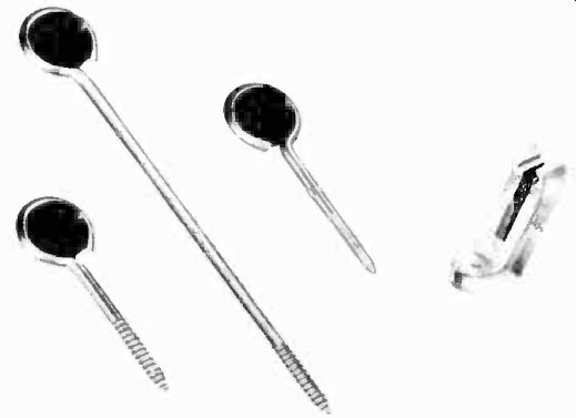
Figure 10. Stand-off insulators.
(courtesy Ampnenoi)
Pliers (long nose, side cutting, diagonal, and slip-joint)
Hack-saw 6-inch adjustable end wrench Half-inch cold chisel Socket wrenches (5/16-inch and one quarter-inch)
Half-inch wood chisel Friction and rubber tape Screw drivers (small medium, large, and off-set)
Claw hammer
Center punch
Files (round, half round, bastard)
Electrician's knife
Emery cloth (assorted)
Flashlight
13. Antenna Kit
This should consist of an antenna, reflectors which may be needed, and the antenna mast. If an extension mast is called for, this should be included.
14. Mounting Brackets
Several types of mounting brackets for supporting the antenna should be carried in the truck. If a high mast is used which cannot be fully supported by a mounting bracket alone, guy wires should be included in the kit.
INSTALLING THE RECEIVER AND ANTENNA
8-22 Transporting the Receiver. When the receiver has been checked and all accessory apparatus for the installation assembled, the installation crew is ready to transport the equipment to the place where it is to be installed. Table models and small consoles can be handled by two men and conveyed on a dolly to and from the truck and into the building. A very large receiver imposes all the problems of moving a good-sized piano. The installation crew may wish to move such a set, or else call in professional movers for the job. In buildings without elevators, it may be necessary to erect a hoist on the roof to lift a receiver of large size. If elevators are available, three men can usually handle a large console receiver on a dolley.
The receiver should be brought to the building and placed in its approximate location, but not against the wall. Sufficient room should be left for adjustment of controls on the back of the receiver, alter the antenna is permanently installed.
With the television receiver tentatively located in the room, the installation crew should proceed to the job of erecting the antenna and laying the transmission line. In this discussion consideration will be given first to the installation procedure for locations where simple antennas (single and double dipoles, and their variations) may be used successfully. Later in this section, complex installations, which require deviation from regular procedures, will be discussed.
8-23 Assembling the Antenna Kit
Instructions for assembling the antenna are provided by the manufacturer. Assembling the antenna can absorb a great deal of valuable time if the antenna is not properly designed. For this reason, an organization which installs television receivers continuously should choose antennas which have been designed so that they maybe assembled in a reasonable period of time.
If the elements of the antenna can be adjusted for the frequency range of the operating stations, they should be set for one quarter the wavelength of the mid-frequency in the range. It may be necessary later to readjust the elements to favor a weak station.

Figure 11. Step-by-step method of preparing coaxial cable by unbraiding and
tinning braid. A, cut back rubber insulation. B, score braid. C, twist scored
braid and cut back insulation to expose center conductor. D, tin braid and
add lug.
If it is expected that parasitic elements will be required to obtain good reception, these rods should be attached to the antenna.
After the antenna array is assembled on the supporting mast, the transmission line should be attached to it.
8-24 Attaching the Transmission Line
There are several methods for finishing up the end of the transmission line and attaching it to the antenna terminals. Three methods are suggested for coaxial cable, which is more difficult to prepare than parallel-line.
The simplest method for preparing coaxial cable is to cut back the rubber insulation around the braid as far as necessary. With a scriber or an ice-pick, the braid is then un-weaved back to the insulation. The plastic insulation separating the center conductor and the braid is then cut back about one inch to expose the center conductor. The opened braid is tinned and forms the ground lead, as shown in Figure 11. Both the center conductor and ground lead can then be connected to the antenna binding posts with soldering lugs.

Figure 12. Finishing end of coaxial cable by tinning end of cable and scoring
tinned braid. A, cut back rubber insulation. B, dip braid into solder. C,
score braid and peel off. D, attach lead and lug to braid.
Another method of finishing off coaxial cable is shown in Figure 12. The rubber covering is cut back and the entire end of the cable quickly dipped into a lead pot. By scoring the tinned braid at the desired point with a knife, it may then be peeled off without the undesirable fraying which normally occurs. Connection may be made to the braid by wrapping two or three turns of a length of tinned solid wire around the braid and quickly soldering it to avoid melting the plastic dielectric.
Some technicians object to applying solder to the coaxial cable because it becomes brittle and snaps easily when whipped about by the wind. A method of finishing off the end of the transmission line which eliminates the need for soldering is shown diagrammatically in Figure 13. Of the three methods, this one provides the strongest and most durable connection to the antenna.
The outer covering is first removed from about six inches of the cable. With a pointed tool, such as an ice-pick or a scriber, the braid is pushed apart three quarters of an inch from the place where the outer covering has been cut. After the hole in the braid has been made, the inner conductor and its insulation are pulled through the hole. The braid is then pulled until it stretches to maximum length. The insulation is removed from about one inch of the inner conductor and the cable is ready to be connected to the antenna or the receiver.
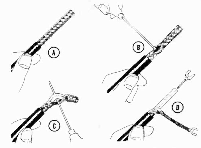
Figure 13. Finishing end of coaxial cable by making hole in braid. A, cut
back rubber insulation. B, make hole in braid. C, pull center conductor through
hole. D, strip insulation off center conductor and make hole at end of braid.
A parallel line is relatively simple to attach to the antenna.
The polyethylene insulation is split in the middle and the ends are stripped with a knife. The open ends may be wrapped around the terminal studs and bolted, or they may be soldered to lugs which can be slipped over the studs, as shown in Figure 14.
8-25 Stringing the Transmission Line. Once the transmission line is connected to the antenna, it is desirable to run the line to the receiver. This will enable contact between the roof technician and the observer at the receiver if sound-powered phones are used. A sufficient length of cable should remain on the roof to permit probing for the best antenna location.
Some means of fastening the line to the antenna mast should be used. This is necessary because the point where the line is attached to the antenna will not stand much strain without breaking. Several devices are available for this purpose. The type shown in Figure 15 is one of the best.
Insulated porcelain eyelets, or similar supports, should be used to hold the line away from metal or brick buildings. If the house is made of wood, the line may be attached directly to it with insulated staples. The insulated supports should be spaced about every 12 feet along the line. The eyelets are installed first and the transmission line is dropped from the roof and threaded through successive eyelets.

Figure 14. Method for connecting twin-lead to antenna. (courtesy Taco)

Figure 15. Mast eyelet for holding twin lead. (courtesy JFD) When the side
of the building is constructed of brick or stone, the problem of screwing
the eyelets into the wall is somewhat difficult to solve. Elsewhere in this
section, several methods of drilling holes in masonry are described. After
drilling, the holes are plugged with wood or expansion bolts, into which the
insulated eyelets are screwed.
The installation crew should carry an assortment of insulators, clamps, expansion bolts, and screws of various sizes to meet the requirements of all installations.
When locating the insulating supports, care should be exercised that they are not too close to metal surfaces such as drain gutters, pipes, or metal roofs.
When all eyelets have been mounted, the transmission line is dropped through them to the point where it is to enter the building.

Figure 16. Drilling window sill at an angle to make hole for lead-in
Ribbon-type transmission line may be run into the building under a window sill. It should be neatly tacked to the window frame so as to conform to the shape of the molding. To run coaxial line into a building, a hole must be bored through the side wall. One means of making an entrance is to drill a one quarter inch hole through a window sill. A high speed electric drill and 18-inch bit may be used to make this hole. The hole should be drilled from inside the house to the outside with the drill tip at a downward angle, as shown in Figure 16. Drilling the hole at an angle prevents water from running into the building. If a cable is used which fills the hole, no caulking is necessary. If the transmission line does not completely fill the hole, the hole should be closed-with caulking compound after the line is fed through it. The cable is run through the interior of the building along the path that it will eventually be permanently tacked. Enough slack should be allowed when connecting it to the receiver to enable the set to be moved for cleaning or for changes in layout of the room.
8-26 Orienting the Antenna. With the antenna and receiver connected by transmission line, two-way communication may be established over the phone system and the task of orienting the antenna for optimum reception begun. The technician on the roof probes different areas and rotates the antenna, while the observer at the receiver watches the test pattern of one of the stations and indicates to the roof observer which of the antenna positions affords the best reception. The receiver is then tuned to another station and the procedure repeated. This routine is tried for each station until the best compromise orientation of the antenna is obtained.
If the signals from each station are about equal in strength, a compromise on the length of the antenna elements can be made by cutting them for a frequency midway between the upper and lower channels. If one of the stations is weaker, the dipole length should be adjusted to favor that station.
8-27 Multipath Signals. If there is trouble from multipath signals, the antenna must be oriented to minimize the ghost effects in the picture. If no position of the simple dipole will give results, then a double dipole should be tried. Finally, reflectors should be added if necessary.
Very often it is of aid, when orienting the antenna so as to minimize ghost reflections, to be able to locate the object which is causing the reflection. The air-path distance to the reflecting surface can be estimated by analyzing the ghost picture which appears on the receiver screen. Knowing this distance, it is possible to pick out the reflecting surface.
Since a reflected signal travels a greater distance than the direct signal, it arrives later than the direct signal and, therefore, causes a ghost. The approximate additional air-path distance traveled by the reflected signal maybe computed from the following considerations:
1. The beam in the picture tube moves from the left to the right side of the screen in approximately 53 microseconds.
2. Since radio waves travel approximately 1000 feet in one microsecond in air, the length of one horizontal line represents approximately 53,000 feet, or about 10 miles of signal travel.
3. The approximate additional air-path distance traveled by the reflected signal is therefore d x 10 miles,
w
where W is the width in inches of the picture on the receiver screen (excluding blanking), and d is the distance in inches measured between the direct image and the ghost image. For example, if the picture is 10 inches wide, and the ghost is displaced one inch, the additional air-path distance traveled by the reflected signal is 1.0 (approx.) 10 = 1 mile a 10.0 approx.) Ghosts which appear in the picture may also be caused by reflections on the transmission line and cannot be eliminated by orienting the antenna. To determine whether a ghost is due to a multipath reflection or an incorrectly terminated transmission line, first compute the air-path distance of the ghost as described above. Then compute the equivalent air-path reflection length of the transmission line. This value is 2L feet, k where L is the total length of the transmission line in feet, and k is the velocity of propagation of the line (approximately 0.83 for twin-lead). As an example, if L is 100 feet and k is 0.83, the equivalent air-path distance of a reflection caused by an improperly matched transmission line would be 2 x 100 240 feet.
0.83 If the ghost were due to line reflection, it would be displaced on the screen by a distance equivalent to 240 feet, or less than one twentieth of a mile. Compare this value with the computed additional air-path distance of the ghost to determine whether the ghost is due to line reflection or to an external reflection. An external reflection can be avoided by properly orienting the antenna. A line reflection can be eliminated by using an impedance matching transformer, described later in this section.
8-28 Mounting the Antenna. After the most suitable site has been located for the antenna, the antenna may be permanently mounted. The manner in which the antenna is mounted depends upon the shape of the object to which it is fastened, and the material of which the object is made. Described below are typical methods for supporting antennas. A number of good supporting brackets are available commercially, which simplify the problem. In some cases, the technician may have to construct a mounting to suit the needs of a particular installation.
8-29 Mounting on a Chimney. A chimney is a good support for an antenna. The antenna mast may be fastened to the chimney by several methods. Figure 17 shows an antenna pole fastened to a chimney with two pipe clamps. Two holes are drilled into the brick for each clamp. Expansion bolts are then inserted into the holes. Machine screws, which fit into the threaded inserts of the expansion bolts, hold the clamps and pole.

Figure 17. Antenna pole fastened to chimney with two pipe clamps.

Figure 18. Chimney mounting bracket. (courtesy South River Metal Products)

Figure 19. Wall mounting bracket. (courtesy Taco)
Another means of fastening the antenna pole to the chimney is shown in Figure 18. An adjustable bracket, which fits most chimneys, is used to hold the mast. The steel bands are placed over the chimney and are held in place by tightening the studs.
The antenna pole is slipped through the holes provided and the studs tightened. A good chimney bracket eliminates drilling into the brick, takes little time to mount, is sturdy and durable, and therefore preferred.
8-30 Mounting on a Wall. If the antenna is mounted on a wall, the same type of clamps used for mounting on a chimney may be used. Wood screws may be used to hold the clamps if the wall is made of wood. For mounting the clamps on a wall made of masonry, expansion bolts and machine screws should be employed. Several brackets designed specifically for wall mounting are commercially available.
The brackets shown in Figure 19 hold the antenna mast away from the wall permitting it to pass such projections as roof eaves.
8-31 Mounting on a Vent Pipe. Almost every roof has one or more vent pipes coming through it. Brackets are available which make it possible to mount an antenna on such a pipe, as shown in Figure 20. Before deciding on a vent pipe mounting, make sure that the vent pipe is secure and will provide a reliable support. As a rule, vent pipes are suitable mountings for light antennas with little wind resistance, such as a dipole or folded dipole. If the antenna is heavy, it is better to choose another more suitable way to support it.

Figure 20. Bracket for mounting on vent pipe.
8-32 Mounting on the Roof. As a general rule, an antenna should not be bolted directly to a roof. Drilling holes into the roof covering usually ruins its weatherproofing properties.
Most roof coverings are guaranteed by the roofing companies which lay them. Any damage to this covering caused by the installation of an antenna may be grounds for a legal suit against the service organization. It is therefore wise to avoid mounting an antenna directly to a roof, if possible. If it is absolutely necessary to rest the antenna on the covering of a flat roof, then the type of mounting shown in Figure 21 should be used. The antenna pole is set on a block of wood. A hole, the diameter of the pole, is counter-bored in the center to prevent slippage of the pole.
Guy wires, attached to the antenna pole, are fastened to the surrounding roof parapet or other objects. Instead of counter boring a hole, a pipe staple or a mast base, such as shown in Figure 22, may be fastened to the board to hold the antenna pole.
8-33. Window Sill Mounting. In rural areas, or where urban apartments are located in high buildings, it is often possible to obtain good reception by simply mounting the antenna outside a window. The mounting shown in Figure 23 is suitable for this purpose.
8-34 Universal Mounting Bracket. A variety of mounting brackets are available on the market. Many of these brackets can be used for several types of mountings and are often referred to as "universal" mounting brackets. Some of the brackets currently being marketed are of ingenious design and will save the installation crew many hours of labor. If universal ...

Figure 21. Mounting
antenna on a roof.
... brackets are used, a careful choice should be made, since a few of the brackets available are rather flimsy and difficult to use.
Figure 24 illustrates two types of brackets and the manner in which they can be used. Both brackets can be used for wall or chimney mounting. The bracket on the bottom is particularly suitable for chimney or corner mounting.
A third type of mounting bracket, which can be used in several ways is shown in Figure 25. It is particularly suitable for mounting on a sloping roof. This type of mounting requires that screws be tapped into the shingles. If this is to be done, the permission of the owner should first be obtained. The screws should be covered with caulking compound to prevent water seepage. Usually, one can avoid mounting the antenna pole on a shingled roof by fastening it to the chimney or by mounting the bracket on the gable of the roof.

Figure 22. Mast base. (courtesy Taco)

Figure 23. Window sill mounting bracket. (courtesy JFD)

Figure 24. Two types of mounting brackets and the manner in which they are
used. (courtesy General Cement).

Figure 25. Bracket which can be used in several ways but is particularly
suited for sloping roof. (courtesy Workshop Associates)
8-35 Antenna Towers. In weak signal areas it is sometimes impossible to obtain a usable signal unless a tower of considerable height is used. Increasing the height of the antenna makes it possible to receive direct signals which are otherwise blocked by intervening buildings or landmarks. A tower for mounting a television antenna is shown in Figure 26. The tower shown weighs only 65 pounds. Its light weight, structural strength, and ease of assembly make it particularly adaptable to television use.
The following precautions in setting up towers should be noted.
1. If the tower is to be mounted on a roof, check with the builder to make certain that the tower's weight can be supported.

Figure 26. Lightweight tower for mounting television antenna. (courtesy Easy-Up
Tower Co.)
Take into account the fact that during the winter, ice forms on the tower and increases its weight.
2. Towers which extend above a certain height must be marked with a light on top. Check with the Civil Aeronautical Authorities in the area for the height at which towers must be marked.
3. Metal towers, which are mounted on the roof, should be grounded so that they do not constitute lightning hazards.
8-36 Guying Antenna Masts. Antenna masts up to about 40 feet in height may be constructed by the technician by coupling sections of pipe together. One of the previously described mounting brackets can be used for supporting the bottom of the mast, while guy wires hold it erect. The method for attaching guy wires is shown in Figure 27. At least three guy wires, spaced 120° apart, are required for adequate support of a ten-foot mast.
Between ten and twenty feet, six guy wires are recommended; and masts above twenty feet require as many as nine guy wires.
The point on the pole where the guys should be attached, and the distance they should extend from the base, are determined by the height of the antenna pole. These dimensions are shown in Figure 27.

Figure 27. Guy-wire spacing.
No. 6 and No. 8 stranded steel wire is generally used for guy wires, although some manufacturers of antenna kits may recommend other sizes for a particular structure. The guy wires should be broken by insulators at intervals which are shorter or longer than the length of the antenna. This prevents the guy wires from resonating at the frequencies for which the antenna is tuned. Turnbuckles (Figure 27) may be inserted in each guy wire leg to take up slack in the wire.
When the antenna is located at a point where it is impossible to space the guy wires 120° apart, an outrigger should be used.
An installation using an outrigger td mount the antenna near the edge of a roof is shown in Figure 28.
8-37 Securing the Transmission Line. After the antenna it mounted, the transmission line should be permanently tied down To prevent the line from swaying in the wind, tape or clamp i to the antenna pole and then run it along the roof to the side o the building, taking care to keep the line away from metal objects. Insulating devices suitable for this purpose are describe elsewhere. All slack in the line should be removed up to the point where the cable enters the building.
Inside the building, the transmission line may be concealed behind molding or run along the tops of the base-boards a shown in Figure 29. Tacks or staples should be used to hold it in place. Care should be exercised that the tacks or staples do not pierce the cable and cause a short. Normally, the line should be kept off the floor to prevent damage to it. When the floor is covered with a broadloom rug which extends up to the base-board, the cable can be forced between the edge of the rug and molding, and be completely hidden. No damage can result to the cable when it is fastened in this position.

Figure 28. Outrigger used to obtain proper guy spacing.

Figure 29. Two methods of running transmission line inside of building.

Figure 30. Circuit and appearance of line matching transformer.
An ideal way to run the line when a receiver is installed on the ground floor of a private dwelling is across the beams of the cellar ceiling and up through the floor, directly behind the television receiver. In an installation of this type, the transmission line is run from the roof, down the side of the building, and through a window sill in the cellar. It is then brought across the ceiling beams and up to the receiver through a small hole in the floor. When running the line in this manner, do not pull it around pipes, radiators, or other metal objects.
The cable is finally run up to the receiver through the floor.
Allow several feet of line to be coiled up behind or inside of the receiver, so that the set can be moved away for servicing and housecleaning.
After the transmission line has been installed, a final check for a short in the line should be made. Connect an ohmmeter across the receiver input terminals. An open circuit reading should be obtained if the line is not shorted.
8-38 Matching Transmission Line to Receiver. Television receivers are being manufactured with antenna input impedances of 72 and 300 ohms. As a rule, a transmission line whose impedance matches that of the receiver should be used.
If it is necessary to use a transmission which does not match the impedance of the receiver, a matching transformer should be provided. Otherwise, the performance of the installation may be seriously impaired.
The circuit and appearance of a suitable matching transformer are shown in Figure 30. This transformer consists of a six turn primary and a 12-turn secondary. A special core material is used. The transformer will match a 72-ohm line to a 300-ohm line to a 72-ohm receiver.
8-39 Grounding the Receiver and Antenna Mast. A television receiver should be connected to a good ground to protect the user in case of breakdown of the high voltage transformer. To reduce noise pickup, the antenna mast should also be grounded.
If coaxial cable is used, the outer braid should be grounded in order to take full advantage of the shielding properties of this type of transmission line. These objects may be fastened to a pipe driven into the ground, to water pipes, or any other well grounded metal conductor.
8-40 Lightning Arrestors. The building codes of some municipalities require that a lightning arrestor be fitted to antennas and other metal objects on a building. The service organization Figure 31. Lightning arrestor. (courtesy RCA) should check the building codes of each area in which it installs antennas to determine whether a lightning arrestor is required by law.
In areas where lightning arrestors are not mandatory, the technician should use his discretion as to whether lightning is likely to strike the building. If the antenna is surrounded by higher metal objects on other buildings, there is little likelihood of lightning striking it. If any doubt exists as to the susceptibility of the building to lightning, it is best to install a lightning arrestor.
A typical lightning arrestor is shown in Figure 31. The transmission line is placed in a slot and a cap placed over it to hold it in position. The arrestor should be mounted at a point close to where the line enters the building. If a grounded pipe is close by, the arrestor may be secured to it. Otherwise a lead should be run from the arrestor to a metal stake in the ground, to a water pipe, or other object which is known to be well grounded.
Unless the ground connection is good, the lightning arrestor will be ineffective.
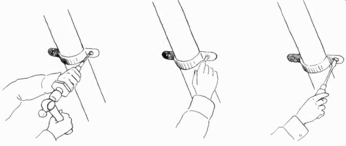
Figure 32. Drilling and mounting to masonry.
8-41 Drilling Holes in Masonry. The quickest means of drilling holes in brick is to use an electric drill with a masonry bit.
A one-half inch slow speed drill is best suited for this job.
About 100 feet of power-cord should be available to connect the drill to an outlet in the building. When making holes in a brick structure, the holes should be drilled into the brick itself, and not into the cement between bricks. Holes in the cement cause leaks in the wall. If the drilling is done carefully, the hole may be made entirely with the electric drill and masonry bit. However, since there is the likelihood of overheating the expensive bit while starting the hole, it is recommended that the hole be started with a rawl tool.
If electric power is not available, a percussion drill may be used. This is slower than using an electric drill, but is the only method possible when electric power or an electric drill is not available. The drill is rotated while being hit with light blows by the hammer. With a little experience in controlling the drill and hammer the technician can make holes comparable to those produced with an electric drill. Figure 32 shows holes being made with a percussion drill.
After the hole has been made, an expansion shield is inserted into it as shown in Figure 32. The type shown is intended for use with nails. Other types are available for use with machine screws.
An expansion shield is not necessary when little strain is to be encountered, as with transmission line eyelets. For such purposes a wooden peg may be driven into the hole and the eyelet screwed into the peg.
8-42 A Typical Installation. At this point it is well to review briefly the important features of a typical antenna installation.
Figure 33 shows all the features of a completed installation.

Figure 33. A typical installation.
The antenna and reflector are mounted on a pole near the edge of a roof. The pole rests on a pipe staple and is secured to an all-purpose mounting bracket which is fastened to the roof. If the screws which hold the bracket pierce the roof insulation, tar or other sealing compound is used to cover the screws.
The transmission line is passed through insulators mounted on the antenna pole to keep it from whipping in the wind. The line is run along the roof and down the side of the building. Insulators are used to fasten the line to the roof and brick wall.
The lead is brought into the building through a hole in the wall and attached to the antenna input terminals of the receiver. A lightning arrestor is attached to the transmission line near the point where it is brought through the wall. The receiver is grounded by running a lead to a steam or water pipe in the apartment.
The foregoing discussion of antenna installations has dealt with those cases where little difficulty is encountered in obtaining good reception.
SPECIAL PROBLEMS
8-43 No set procedure can be given for difficult installations.
At best, only examples of typical problems can be presented as a guide to the technician.
Only experience will enable the installing technician to tackle any type of antenna problem without difficulty. Trial and error techniques must be followed to some extent under non-standard conditions. The technician will often use methods which do not follow normal procedure but which, in the final analysis, bring results.
8-44 Typical Difficulties. Very often the technician is called upon to install receivers at locations where normal practice will not give satisfactory results. Some of the problems encountered are illustrated in Figure 34.
B illustrates a location, in the primary service area of a station that suffers from undesired reflections and an interfering signal on the same channel. These difficulties can be eliminated by utilizing an antenna with suitable directive characteristics.
D illustrates another location in the primary service area of a station. The location is such that the direct signal path is blocked by an obstruction, in this case, a tall building. Two reflected signals reach the location and therefore a high-gain directive antenna can be used to pick up the strongest reflected signal and at the same time eliminate the other reflection.
E and F illustrate locations on the fringe of the station's service area. While it is not always possible to obtain satisfactory reception at distances of over fifty miles from the station, good results can often be secured by using high gain arrays mounted on towers.
Weak signals, excessive noise, interference from other services, and combinations of these troubles also result in installation problems which require special procedures. The following paragraphs describe the general procedures to follow when these problems are encountered.

Figure 34. Typical reception problems. (courtesy Workshop Associates)
8-45 Weak Signals. When the signal strength at the receiver is of insufficient amplitude, only a faint picture with considerable noise and poor synchronization can be obtained. if the signal level is below the minimum for which the receiver is designed, several things can be done to increase its strength at the input to the receiver.
Increasing the height of the antenna generally increases the signal pickup. The increased height means that a longer transmission line, with greater loss, must be used. As a rule, the loss will not be great enough to offset the increased pickup secured, unless the use of a taller mast makes it necessary to locate the antenna in a new location, further from the receiver.
At installations where the signal strength is low, every effort should be made to locate the antenna as close as possible to the receiver in order to minimize the length of transmission line required. If a long line must be used, choose one which has low loss. While they are normally considered to be prohibitively expensive, air-spaced coaxial and parallel lines are available which have extremely low losses.

Figure 35. High-gain, five-element array, suitable for reception of single
high band television station. (courtesy Roger Television)
If the signal level is low, a considerable improvement can be brought about by using a high gain array. Many types are available, from the dipole and reflector type to complex stacked antennas and reflectors. The ultimate in antenna arrays is a series of three element parasitic beams, one for each station to be received. Each beam is especially directed and tuned for a specific station.
For channels seven through thirteen, five element parasitic beams are available which give excellent results. The appearance of such an antenna is shown in Figure 35. Five element beams are not satisfactory for use on the low-band channels because they respond to a comparatively narrow band of frequencies. Antenna bandwidth is expressed as a percentage of the resonant frequency of the antenna. An antenna design which gives a bandwidth equal to five percent of its center frequency will have a bandwidth of approximately 2.5 megacycles on channel two. If cut for channel thirteen, it would have a bandwidth of approximately 11 megacycles, more than sufficient to cover a six megacycle television signal.
Other types of high-gain antennas are described in Section 5.
The performance of a television receiver can often be considerably improved with respect to weak signals by the addition of a pre-amplifier or "booster". This is particularly true when the receiver has an RF amplifier of compromise design or no RF amplifier at all.
If the RF amplifier in the receiver has not been designed for optimum results, a booster amplifier of good design will improve the signal-to-noise ratio of the receiving equipment. This is true because, as a practical matter, the first stage of a receiver determines its absolute sensitivity. The noise generated in the first stage establishes the signal-to-noise ratio on weak signals and thus the overall performance of the receiver. If the noise, due to thermal agitation and shot effect, is equal in magnitude to the received signal, a satisfactory picture will not be obtained. It is evident that the noise generating characteristics of an RF amplifier are just as important, and in many cases more important, than the gain it contributes.
When a booster amplifier is added to a receiver, the first stage of the booster becomes the first stage of the receiver and the minimum signal amplitude which will produce a satisfactory picture is determined by the booster. It is apparent, then, that if the noise characteristics of the booster surpass those of the first stage in the receiver, an improvement will be brought about.
Many of the booster amplifiers presently being marketed have not been designed so as to give the best results obtainable, and it is therefore important that a careful choice be made. The noise generating characteristics of the tubes used is one of the factors which determines the effectiveness of a booster amplifier. The noise generated by the tube is expressed in terms of the resistance of an actual resistor which would create noise of equal amplitude.
Since triodes have lower equivalent noise resistances than pentodes, they are superior in this respect. As an example, a 6J4 triode has a noise resistance of 210 ohms, while a 6AK5 pentode has a noise resistance of 1800 ohms. Connected as a triode, the 6AK5 has an equivalent noise resistance of 385 ohms, and is superior in this respect to the same tube, pentode connected.

Figure 36. Cascode RF amplifier.
The circuit used also determines the noise characteristics of an amplifier, as well as its other characteristics, such as stability. A triode used in a grounded-grid circuit is approximately equivalent to a well designed pentode amplifier. A circuit capable of probably the best performance obtainable at this time is one referred to as the "Cascode". A simplified diagram of such a circuit is shown in Figure 36. This circuit uses two triodes, a grounded-cathode stage, followed by a grounded-grid stage. While this circuit has again equivalent to that of a single pentode, it is superior because it generates less noise.
While the improvement in signal-to-noise ratio secured by the use of a booster is important, several other advantages are also realized. Among them are increased gain, improved image rejection, and reduction of local oscillator radiation.
When selecting a booster, it is important that its input and output impedances match those of the transmission line and receiver input.
Many boosters have response characteristics which are not sufficiently broad to cover the complete television signal. As a result they attenuate portions of the signal, causing loss of video response. The response characteristic of a booster should therefore be determined before it is selected.
The following is a summary of the points to remember in attempting to secure satisfactory results under weak signal conditions.
1. Use a high gain antenna or antennas.
2. Mount the antenna as high as possible.
3. Mount the antenna as near to the receiver as is practicable, in order to keep the transmission line short.
4. Use low-loss transmission line.
5. Use a pre-amplifier of good design and construction.
The technician should be careful not to mistake a noisy location for one where the signal level is low. Booster amplifiers are only effective if the prevalent noise level at the installation is comparatively low. If a great deal of man-made noise is encountered, somewhat different procedures, to be discussed later, should be followed. If the signal is weak and in addition manmade noise is high, both procedures should be followed.
8-46 Man-made Noise. Ignition systems of automobiles, electric motors, trolley lines, and other electrical apparatus cause man-made static which enters the receiver via the antenna or the transmission line and cause the picture to tear. Other random noises, either in the atmosphere or in the set, evidence themselves as light and dark spots in the picture. From a distance, the effect resembles snow.
The effects of noise can be minimized or eliminated in two ways. One is to increase the signal at the receiver and simultaneously reduce the noise being picked up by the antenna system. The second method is to eliminate or reduce the noise at its source.
The methods outlined in the paragraph on weak signals, with the exception of the part referring to booster amplifiers, will increase the signal at the receiver and are therefore helpful.
In addition to raising the height of the antenna, an effort should be made to find a location for it which results in lower noise pickup. High gain arrays are effective because they increase the signal at the receiver in addition to reducing noise pickup.
They pick up less noise because of their directivity. If an antenna is not sensitive to energy reaching it from the direction of the noise source, it will not pick up the noise. Thus, an improvement in the overall signal-to-noise ratio of the installation results.
The use of a shielded transmission line will help reduce noise effects. In noisy locations, coaxial line is preferable to parallel line because its pickup is lower. If parallel line is used, it should be twisted several times for each foot of length, since this procedure reduces pickup. Several new shielded-pair lines are available, which are superior to both coaxial and parallel pair lines with respect to noise pickup. These cables have comparatively high losses and are only suitable when a short transmission line is required.
If the source of the noise is known, the transmission line should be relocated so that it is as far away as possible from the noise source. This should be attempted even if it necessitates the use of a longer line. Other points which should be checked are the impedance match at the receiver input and at the antenna. If a shielded line is used, make certain that the shield is connected to a good ground.
As previously mentioned, noise can also be eliminated at its source. Commercial filters are available for this purpose. In many instances, 0.05 mf condensers, connected across the power line at the point where it enters the electrical equipment causing the noise, will prove effective. While this method of handling the problem is the most effective, it is only applicable in a few instances, as with oil burners and other appliances in private dwellings. In urban areas, the source of the noise is usually not easy to determine, and when it is, the cost of filters is prohibitive. It is therefore best, inmost cases, to follow the procedure outlined for improving the antenna system.
Summarizing the procedure to be followed for reducing noise pickup:
1. Use a directional, high-gain antenna.
2. Attempt to find antenna location which gives minimum noise pickup.
3. Mount antenna as high as possible.
4. Twist parallel-line or use coaxial or shielded-pair line with good ground.
5. Locate transmission line as far as possible from noise source.
6. Make certain transmission line, antenna, and receiver, are correctly matched.
7. Locate and place filters at noise sources.
8-47 Too Strong a Signal. In a few instances, a receiver is situated in an area where the signal strength is so high that the input circuits are overloaded. This condition is characterized by a loss of synchronization, sound modulation in the picture, and an over-contrasty or distorted image.
To prevent the effects of too strong a signal, the television receiver is equipped with a contrast control, and often with automatic gain control. However, the contrast control is almost always located in the video IF circuit, or the video amplifier stage.
An extremely strong signal will overload the first RF stage be fore the contrast or gain control can be of help. Obviously then, until means are provided in television receivers to reduce signal strength before the first stage is reached, this must be done by the installing technician. Preferably, the task should be accomplished without the need to remove or rewire the chassis. This can be done by using an external attenuator in the antenna transmission line. Several commercial attenuators are available.

Figure 37. The Tel-Adjust and the Tele-Pad, used to reduce too strong a signal.
(courtesy Roger Television)
Figure 37 shows an excellent one called the Tel-Adjust.
Basically, the attenuator is a low-loss switch and a series of attenuator pads made up of half-watt carbon resistors. Provision is made to mount different fixed pad arrangements in the
box for different types of transmission lines. By means of the switch, a choice of several attenuation values is available, and each station's signal may be attenuated by the required degree even though the signal level from each station varies greatly.
Several types of fixed pad arrangements can be used in the transmission line. For balanced lines, however, such as 300 ohm twin-lead, a balanced attenuation network is preferred, such as the "O" and "H" types shown in Figure 38. On the other hand, when coaxial cable is used, an unbalanced pad is sufficient, and cheaper to install. Examples are the "I" and "Pi" types shown in Figure 38.
In order to install these attenuator pads, two things must be known: (a) how much attenuation is needed, (b) the resistance values which will produce exactly the needed attenuation without upsetting the impedance match between the receiver input and the transmission line. The signal strength is measured with a field strength meter and the needed attenuation calculated. A simpler method is to insert a variable pad box into the transmission line and vary the attenuation until the trouble is eliminated. If the variable attenuator is calibrated, the correct amount of attenuation can be read directly. Such a variable attenuator is shown in Figure 37 and is known as the Tele-Pad.
This variable pad box has a constant impedance equal to that of the transmission line and an accurately calibrated dial which reads to 30 db attenuation in steps of 3 db.
In using the Tele-Adjust and Tele-Pad, the first step is to determine the amount of attenuation needed on each overloading station. This is done with the Tele-Pad. When the required amount of attenuation is known, the values of the resistors in the attenuation network may be calculated. To avoid calculations, a table of such values is shown in Figure 38, which lists different attenuation factors and corresponding values of R1, R2, and R3 for 300-ohm and 72-ohm lines. These resistors should be of the half-watt carbon type.

Figure 38. Attenuator network and component values.

Figure 39. Simple wave trap.
8-48 Diathermy Interference. Although most modern diathermy machines are equipped with RF filters so that radiation into the power line is reduced, many machines installed in doctors' offices and hospitals interfere with television reception. When the frequency of the diathermy apparatus is close to the IF frequency of a nearby television receiver, an interference pattern is produced in the television picture. Little can be done at the installation to remove this type of interference. If the diathermy machine can be located, the owner should be asked to cooperate by shielding the machine, by seeing to it that the machine is operating on its correct frequency, and by grounding it properly. An ordinary battery-operated, portable radio is an effective probing device for locating diathermy machines which cause disturbances in the television receiver. A buzzing sound is heard over the entire broadcast band if a diathermy machine is in the vicinity of the portable receiver. As the receiver is brought closer to the diathermy machine, the buzzing sound grows louder. Diathermy machines which are situated as many as several thousand feet away may be located in this manner.
8-49 Beat Frequency Interference. Strong AM and FM broadcast stations near the receiver can heterodyne with the television sound or picture carrier, resulting in a beat frequency which appears on the screen as a series of fine vertical or slanting lines which drift through the picture. If the unwanted carrier is fixed in frequency, it may be filtered out by a trap which is inserted in series or shunt with the antenna transmission line.
A simple way to make a wave trap is to connect a piece of coaxial cable or parallel lead across the antenna input terminals of the receiver. Starting with a piece about two feet long, cut the cable off in one inch pieces, until the beat frequency is eliminated. In this way, the trap is cut to a length which is resonant at the frequency of the unwanted carrier and by-passes it from the receiver input.

Figure 40. Circuit for wave trap.
Another simple wave trap is shown in Figure 39. It is basically a quarter-wave open-end stub of 300-ohm line. The line should be about two feet long. Instead of tuning out the interfering frequency by clipping the line, a tinfoil slider is slipped over it. The slider is moved up and down the stub to tune out the disturbing frequency. The advantage of the slider is that it may be reset if the disturbing frequency shifts. The receiver owner should be familiarized with the slider adjustment if this type of trap is used, since he may have to reset it as the interfering frequency changes. Since the tuning of the trap is affected by hand capacity, a string is added to the stub. The string is held by the user when tuning adjustments are made. The slider should be pushed with an insulated rod such as a wooden pencil with an eraser.
If the simple traps just described are not effective, a trap such as that shown in Figure 40 may be tried. This trap consists of two resonant circuits connected in series with one leg of the line. The tuned circuits are mounted in a shielded box.
These traps should be adjusted to the frequency of the interfering signal. If two interfering signals are present, one trap can be tuned to the frequency of each signal. The two coils should be mounted at right angles to each other to minimize cross coupling.
Several commercial wavetraps are available, which are also very effective.

Figure 41. A typical multiple antenna installation. (courtesy Workshop Associates).

Figure 42. Multiple antenna installation using two six-element beams. (courtesy
Workshop Associates).
8-50 Multiple Antenna Installations. As previously mentioned, the difficulties encountered in poor locations can often be overcome through the use of more than one antenna. Typical multi antenna installations are shown in Figures 41 and 42. In Figure 41 three separate antennas are used. The location is such that one antenna cannot satisfactorily cover more than one station.
Three element parasitic beams are used. Each beam is tuned to a different station and directed so as to obtain maximum pickup from the station to which it is tuned.
Figure 42 illustrates a second multi-antenna installation. Here two six-element parasitic arrays are used. Each array is specially tuned and directed to secure maximum pickup from a single station.

Figure 43. Coaxial switch. (Workshop Associates)
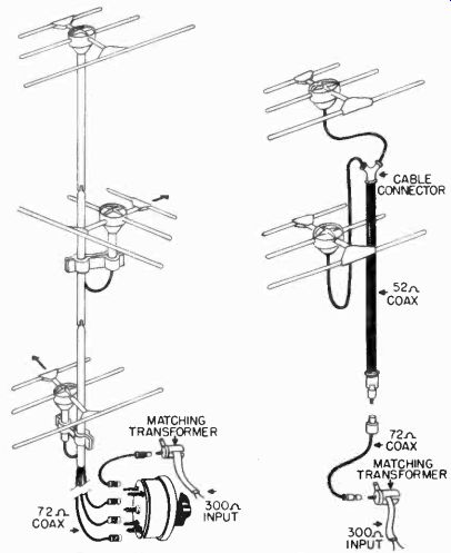
Figure 44. Typical application of coaxial switch.
Similar problems are encountered in large cities where large buildings either block direct signal paths or cause reflections.
It is generally possible to obtain satisfactory results by utilizing separate antennas for each channel or for channels which present particularly difficult problems.
If more than one antenna is used, some means must be provided to permit switching from one antenna to another. A switch suitable for use with coaxial cable is shown in Figure 43. This switch permits the use of as many as four different antennas on a single receiver. It can also be used to advantage in dealers' display rooms were it is desired to connect several antennas to several different receivers.
Figure 44 illustrates the details of the installations of Figures 41 and 42. These installations use the four-position coaxial switch of Figure 43. The three antennas of the installation on the left are connected by coaxial cable to the switch. The output of the switch is connected to an impedance matching transformer which matches the 72-ohm transmission line to the 300 ohm input of the receiver. The second installation consists of two six-element parasitic arrays. These arrays are connected by coaxial cable to a junction; from the junction the signal passes through a length of 52-ohm coaxial cable, and then through an impedance transformer consisting of a quarter-wave section of 72-ohm coaxial cable. If the receiver has a 300-ohm input impedance, a transformer can be added to secure an exact match.
A third multi-antenna installation is shown in Figure 45. Here two antennas are used, one for the high-band channels and the second for the low-band channels. In order to avoid running two transmission lines, the antennas are paralleled and a single line is used. The transmission line is connected to the lower antenna. The top antenna is connected to the lower antenna by a piece of parallel line cut to one quarter of the wavelength of the frequency for which the lower antenna is cut. The same type of line is used for paralleling the antennas as is used for the main transmission line in order to avoid an impedance mismatch.
In cases where the above array is to be used for increasing the signal on the high channels, and no reflections are present, each antenna should be oriented toward the desired stations.
The lines should be connected in phase at the point where they are joined if the orientation of the antennas is not more than 45 degrees apart. Proper phasing is obtained by connecting the left-hand element of one antenna to the left-hand element of the other. The right-hand elements are similarly connected.
If reflections are encountered, mount both antennas on the mast, but connect the transmission line to only one antenna at a time. By rotating the mast, determine the best orientation for ...

Figure 45. Antennas connected in parallel.
... each antenna separately, using a station whose frequency falls within the response of the antenna. When the antennas are properly oriented, tighten them on the mast so that they will both point in the proper direction when the mast is in place. Then parallel the antennas, as above, with a quarter-wave section of line. If any increase in reflections is noticed, try reversing the connections of the main transmission line to the lower antenna.
If this does not improve the picture, try reversing the line which parallels the two antennas; that is, connect the left-hand conductor from one antenna to the right-hand terminal of the other antenna, and the right-hand conductor from the first antenna to the left-hand terminal of the second antenna. If none of these connections of the lines clears up the reflections, it is necessary to use separate transmission lines from each antenna to the receiver.
8-51 Indoor Antennas. The need for indoor antennas usually arises because landlords forbid the erection of individual antennas on their roofs. The objection of apartment house owners to a disfiguring and hazardous maze of antennas is well understandable. As objectionable also is the signal interaction between a number of antennas operating in close proximity, as a result of which reception in the individual receivers may be impaired. The practical solution to this problem lies in the installation by the landlord of a master antenna system which feeds signals to each apartment. Such systems were described in Section 5. However, it will be many years before all apartment houses are equipped with master antenna installations.
Until then the tenant, desirous of having a television receiver in an apartment house where outdoor antennas are not permitted, may be able to secure satisfactory performance with an indoor antenna.
Though indoor installations are difficult, they are sometimes preferable to roof systems. For example, if it is possible to receive good signals in a third floor apartment that is located in a ten-story building, there is little point in erecting the antenna on the roof and investing in the long transmission line.
There is also less likelihood of interference from other antennas when indoor installations are used.
It should not be assumed from this that indoor installations are better in all cases. Actually, very few instances occur in which an indoor installation is preferable. However, no rule can be made and the technician must use his own judgment.
An inspection should first be made of the direction in which all the windows of the apartment face to ascertain whether there are possibilities of "line of sight" reception. If such is the case, an antenna may be mounted on the window sill. Installing the transmission line then becomes a routine matter.
If no direct signal can be obtained, locating the best antenna site becomes a matter of trial. A dipole with sufficient cable between it and the receiver to allow one technician to probe in all the rooms of the house for the best signal should then be tried. The probing should begin near the receiver, the antenna being set in different positions and rotated while the screen of the receiver is watched. If no position of the antenna gives a good picture, the technician with the probe should proceed to the other rooms. If a terrace adjoins the apartment, it should also be tried. When the best position of the antenna has been found for all stations, the observer should look for close-by objects to conceal the antenna. Inside closets, under cornices, and behind moldings are a few locations which have proved successful for indoor antennas. When the dipole cannot readily be concealed, it can be mounted on a wooden rod, and the entire assembly painted a color to match the room. Many people, anxious to have a receiver, have accepted a neat antenna installation mounted in the corner of a room. In other installations, the antenna has been suspended from the ceiling. Figure 46 shows an indoor antenna which can be placed on a table, the receiver cabinet, etc. It can be rotated for the best reception of each station and folded when not in use.

Figure 46. An indoor antenna (courtesy Delson Mfg.)
8-52 Multiple Indoor Antennas. It is very probable that many indoor installations will require more than one antenna in view of the fact that direct or strong reflected signals are not likely to exist for all stations. If probing all rooms does not indicate a site that provides reception of all signals on one antenna, then a second antenna should be tried. These antennas may finally be situated in different parts of the apartment, or may be mounted on window sills facing in different directions, depending upon the location of the various stations with respect to the receiver.
Under the most difficult conditions, a separate antenna may have to be installed for each station.
If more than one antenna is required, a switching arrangement must be provided to enable the owner to select the proper antenna for each station. For installations with two antennas, a double-pole, double-throw knife switch is recommended, wired as shown in Figure 47. Rotary or toggle switches are to be avoided as there is excessive leakage across the contacts at the high television frequencies. The switch can be mounted in a location convenient to the customer, as for example on the side of the cabinet, or concealed behind a curtain near the set.
When three or more antennas are required, a terminal board with connectors can be used. The owner then moves the lead running to the receiver to the proper set of terminals. A coaxial switch, as described under multiple outdoor antenna systems is the ideal solution to the multiple transmission line problem when coaxial cable is used.
Figure 47. Double-pole, double-throw knife switch for connecting two antennas to receiver.
Many apartment houses in which only indoor antennas are per mitted are located so close to the transmitter of one or more stations in metropolitan areas that very often no antenna at all is needed, or at most a piece of coaxial cable approximately one-quarter wavelength long will suffice. A unique installation in New York, located very close to station WCBS-TV, illustrates these conditions. It was found that WCBS-TV came in very well without an antenna. WABD was also strong, but ghosts were in the picture. These could be suppressed by attaching a piece of cable, 39 inches in length, to the receiver antenna terminals and by rotating the cable in an arc until a good signal without reflections was selected. An antenna was needed only for WNBT, and a favorable point in the room was found for it. A terminal board, mounted very close to the receiver, enabled the owner to select either WCBS-TV (no antenna), WABD (a 39-inch piece of cable, mounted on a wooden rod and attached to the receiver at the correct angle), and WNBT (dipole antenna). With this antenna system, the receiver cannot be moved without disturbing the entire field pattern. It should be remembered that, with indoor installations, receivers cannot so readily be moved about. The length and direction of the antenna and transmission line are more critical than for outdoor installations.
8-53 The Power Line. Most television receivers thus far introduced to the public have been designed for operation on 110 volt, 60-cycle power lines. (A few low-priced, small screen a-c/d-c receivers have made their appearance, but thus far they constitute a small proportion of sets sold.) Three non-standard conditions of the power line may exist, any one of which prevents the direct connection of the receiver to the power outlet: (1) direct current, (2) 25 or 50-cycle line, and (3) incorrect a-c voltage. Any of these conditions requires accessory equipment before the receiver can be made to operate.
8-54 DC Line. Rotary converters which change DC to AC have proved suitable for operation with television receivers.
Investment in a high quality converter is advised so that 60-cycle voltage of good waveform is obtained. Otherwise, strong low frequency harmonics may exist which will not be adequately filtered out by the receiver power supply filter. Brush design of the converter is important, because excessive brush noise causes interference with reception. Since the converter is generally located in a closet or in some other poorly ventilated place, it is well to use a converter whose power rating is well above the actual requirements.
Once the converter has been installed, it requires no further attention. A switch mounted on the side or rear of the receiver cabinet will make it convenient to turn on and off. It is not recommended that the technician rewire the receiver's power switch so as to turn on the converter at the same time, because it necessitates another rewiring job, should the customer move into an area with a-c power.
8-55 Voltage Transformer. If an ac power line voltage other than 110 volts exists, a power transformer of sufficient rating to handle the requirements of the receiver and having the correct step-up or step-down ratio will solve the problem. In large console models, there may be room to mount the transformer inside. With small sets, the transformer may be concealed in a closet or behind a piece of furniture. The receiver is plugged into the transformer, which in turn is connected to the power line. No on-off switch is required.
8-56 Voltage Regulators. If a receiver is located in an area where there are continuous line voltage fluctuations, which cause annoying changes in picture size and intensity, a voltage regulator may be used. A voltage regulator is similar to a transformer. Its primary is connected to the power line and its secondary to the power plug of the receiver.
8-57 Frequency Converters. If a receiver is to be used with a 50-cycle or 25-cycle power line, a frequency converter is required. Frequency converters are similar to rotary converters.
The input is connected to the power line and 60-cycle power is available at its output. If such a converter were not used, the power frequency would not be properly filtered by the receiver power supply and difficulty would be experienced in synchronizing the picture.
8-58 Operating the Receiver. The final link in the chain of events between selling the television receiver and its adjustment and installation in the customer's home is the instruction of the owner in the correct operating procedures for tuning the set.
Though operation has been simplified by the reduction in the number of controls on modern television receivers, it is well to give the customer a brief explanation of the function of each control and its effect upon the receiver's performance. At this time, it is also advisable to acquaint the customer with such interference effects as diathermy, auto ignition, etc., which will cause occasional picture disturbances despite the best possible installation.
Since many technicians will often find themselves in the role of salesman, selling techniques are necessary adjuncts to their knowledge. As with any new piece of equipment, the customer will look to the technician for advice and guidance. The technician's knowledge and integrity in selling television receivers is particularly needed now when it is important to help create satisfied receiver owners. A brief illustration is selling will emphasize this point. Suppose the customer lives in an area which is considerably disturbed by ignition noises. This may be a location on a street with heavy automobile traffic, trolley lines, or neon signs. The average customer, unaware of these effects, may choose a low priced receiver which has conventional synchronization. An alert salesman, thoroughly familiar with the advantages of flywheel synchronization, would do the customer a great service by swinging him over to a higher priced model equipped with this circuit, which is more. immune to ignition signals. Similarly, all other features which determine the prices of receivers should be discussed with the customer. For at one time or another he will see another television receiver, and unless his provides a picture of equal contrast, brightness, stability, and sharpness, he will immediately question the integrity of the store which made the sale. By understanding that better performance can only be achieved by a higher priced set, the customer will make his choice and be satisfied with it.
Learn how to interpret test patterns and convey as much information as possible to the customer. Make him aware of those conditions which are the fault of the receiver and those which cannot be avoided even with the best of installations. This type of customer education will pay dividends.