A picture is worth a thousand words. Man has used pictures as a means of communications for many years. If an engineer designed a simple electronic device, for example, it would be difficult to convey his idea to the person who is to fabricate the object without a drawing to show the shape, size and location of the components. Drawings are used not only as plans to fabricate and assemble objects; they are also used to show how to service most products, including radio sets.
The three types of drawings most used in servicing radios are the pictorial drawing, the wiring diagram and the schematic.
A pictorial drawing is a drawing that takes the place of a photograph. It shows the shape, location and relative size of objects. One such drawing is the one in FIG. 1, which shows a circuit mounted on the back of a military radio receiver. Another example of a pictorial drawing, one very useful to a restorer of antique radios, is a drawing showing how the dial cord of a receiver is to be strung.
A wiring diagram is more abstract (less like a photograph) than a pictorial. It also shows the shape, size and locations of components, but the person drawing it takes some liberties. He shows the same parts, but in less detail. Furthermore, he usually shows the wires as being as straight as a string, which usually they aren’t. FIG. 2 is a wiring diagram of the same circuit shown in FIG. 1.
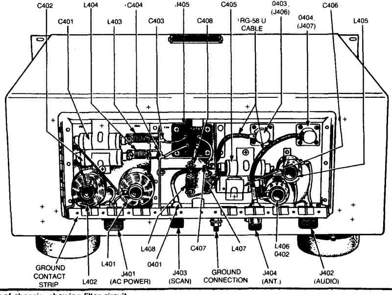
Fig. 1: rear view of receiver chassis.
The schematic represents a still higher level of abstraction. It is not at all like a photograph. It uses symbols to represent electronic parts, and the shape and size of the symbols bear little or no relation to the shape or size of the parts represented. Further, the locations of the symbols often do not reflect the actual placement of the parts in the actual circuit. Usually the symbols are arranged so that the input is placed at the upper left corner, and the signals and action flow from left to right and from top to bottom. FIG. 3 shows the schematic of the same circuit depicted in Figs. 1 and 2.
Service literature for the old-time sets is difficult to come by since these sets are often “orphans”—that is, their manufacturers are out of business. There were a number of guides of service information put out by independent publishing companies that covered the old sets. The most complete is Rider’s Perpetual Trouble Shooter Manuals, which cover the era from 1930 to 1953. Some libraries in medium-size and large cities have complete sets of Rider’s manuals. The information in these runs from a one-page schematic for some sets to 19 pages for one Scott model. There are a number of persons selling copies of schematics and other information from these guides. They charge from 25 cents per page to $3.50 for all the information available for a given model. For the names and addresses of the providers of this service, look in the classified section of Elementary Electronics, Popular Electronics and Radio-Electronics.
Gernsback also published a set of Official Radio Service Manuals back in the 1930s (1930-1937). These will also prove very helpful, if you can find them.
One long-time supplier of service information: Supreme Publications. They supply volumes covering numerous models and also information on specific individual models.
For other sources of servicing information and general information about old-time radio—and for just plain fun reading—I highly recommend Elementary Electronics’ monthly “Antique Radio Corner,” which is presided over by James A. Fred.
To understand schematics, it is necessary to understand the symbols used in them. The following pages show pictorial drawings of the most common radio parts and the schematic symbols for the parts. First we shall consider the unit terms used in electricity and electronics, and on schematics.
UNIT TERMS USED IN ELECTRICITY
A review of the unit terms in electricity is given in this section of the Section. It is essential that the radio restorer have a thorough understanding of these terms so that he can properly (and easily) interpret schematic diagrams, block diagrams, and service block diagrams. The more knowledge you have of electronic theories, the easier it will be for you to read electronic diagrams and schematics. (If you plan to become professionally involved in receiver restoration, or deeply involved as an amateur, it will pay you to study the advanced receiver theory.)
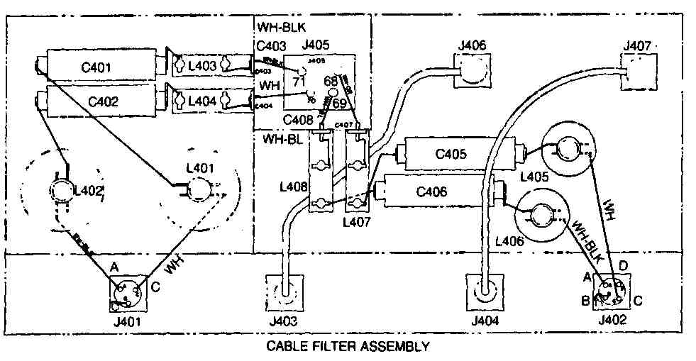
FIG. 2. Filter wiring diagram
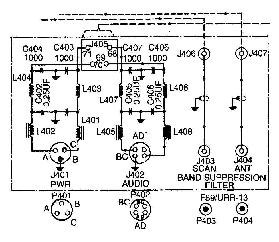
FIG. 3. Filter schematic..
Coulombs
Man has never seen an electron and maybe never will. To simplify the job of counting them, individual electrons are grouped together into a large electronic unit—the coulomb—much like grouping grains of sugar into a larger unit, such as the pound.
Amperes
When 1 coulomb of electricity passes a point in 1 second, 1 ampere of electricity is flowing. Thus, 1 ampere is to electrical flow as 1 gallon-per-minute is to water flow. In other words, we are dealing with the rate of flow. One-half coulomb per second is ½ ampere; 1/1000 coulomb per second is 1/1000 ampere, or 1 milliampere (abbreviated mA).
In radio work, the most used unit of current is the milliampere. With receiving circuits, the range is from 1 or 2 to about 50 mA.
Volts
Volume of current is not always the same. It varies directly with the size of the charge. Work is required to move electrons and create a charge. Consequently, the size of the charge may be expressed in units of work necessary to move the charge.
The volt is the unit used to express the amount of work done to create a charge. One volt of charge is created when 1 joule of work is expended in moving 1 coulomb.
Joules
The joule is the term used to express the absolute unit of work or energy applied. In this application, 1 joule is equal to approximately 0.7375 foot-pound.
A volt, however, actually expresses more than the degree of charge. When you accumulate a surplus of electrons, a reverse of potential energy is created. Thus, 1 volt may also be used as an expression of the potential energy of an object.
VOLTAGES ARE DIFFERENCES IN POTENTIALS
Because it is possible to create an electrical charge by either adding or removing electrons, the energy of two points is not expressed in actual potentials but in differences of potential. When you say an object has a potential of 200 volts, you actually are expressing the difference in the potentials of two points.
Zero Potential
All objects have some potential, but it is common practice to designate some point as zero potential. In a radio, zero potential is usually the frame or chassis of the set. When you say the plate of a vacuum tube is positive 200 volts, you are only stating that the plate is 200 volts more positive than is the chassis.
The rate of current flow is influenced by the magnitude of the difference between the two charges. If the difference between the charges is small, for example, the rate of flow will be low. If the difference is large, the rate of flow will be large.
Negative Potentials
Negative potentials also exist. Although the chassis of a radio is given as zero potential, it is possible for certain parts of a receiver to be at a lower potential than is the chassis. These parts are said to have negative potentials.
You will find the grids of vacuum tubes rated as —5, —10, —50, or —75 volts. This expression means that the grids of the tubes are at a lower positive potential than the chassis by 5, 10, 50, or 75 volts. Don’t let a negative potential fool you. There is just as much wallop between —200 volts and the chassis as between +200 volts and the chassis.
Voltages are Relative
Voltages are relative. Point A in FIG. 4 is given as —200 volts in comparison to the chassis. Point B, on the other hand, is 200 volts more positive than is the chassis. You may say, therefore, that point B is 400 volts more positive than point A. Reversing the expression, point A is 400 volts negative in respect to B.
How about point C? It is 100 volts positive in respect to the chassis, but 100 volts more negative than point B. In respect to A, point C is 300 volts positive.
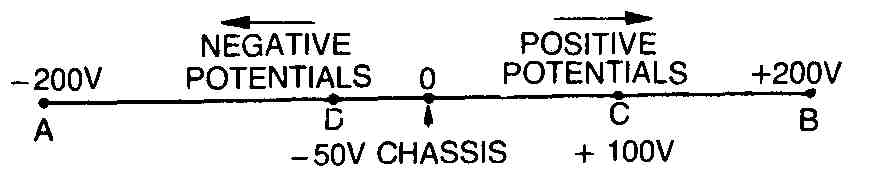
FIG. 4. Relative potentials.
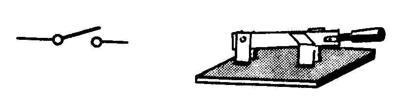
FIG. 5. Single-pole, single-throw switch.
Point D is 50 volts negative in respect to the chassis, but 150 volts positive in respect to point A. Thus, point D is also 150 volts more negative than C, and 250 volts more negative than B.
All these potentials (voltages) are measured in relation to the potential of the chassis. When you state the voltage of an element, therefore, remember that what you state is true only in respect to, or relative to, another point.
Here is a little statement to remember: electrons flow toward the more positive potential. Even if all potentials are negative the electrons move from the most negative toward the least negative potential. The higher the voltage and the greater the potential difference, the greater is the flow of electrons.
INFLUENCING FACTORS
Now that we have covered the essentials of electricity, we will move into the components, their influencing factors, and their symbols. In drawing electronic schematics it would be difficult and time-consuming to represent each component as an actual picture. Instead, standard symbols are used to represent parts and components. The symbols are universal and are readily understood throughout the world.
Before you try to interpret electronic schematics and diagrams, you should become familiar with some of the electronic symbols and their influencing factors on the circuit. A few of the more common electrical and electronic symbols are explained in the following paragraphs and are illustrated as cited.
A simple single-pole, single-throw knife switch is shown in FIG. 5. It makes and breaks a connection for one line, and only at one point. The symbol shows two small circles indicating contact points and a straight line indicating the movable throw switch.
FIG. 6 illustrates a double-pole, double-throw switch. It is similar to the single-throw switch, except that it has two blade switches mechanically connected, and can make and break contact in two different positions.
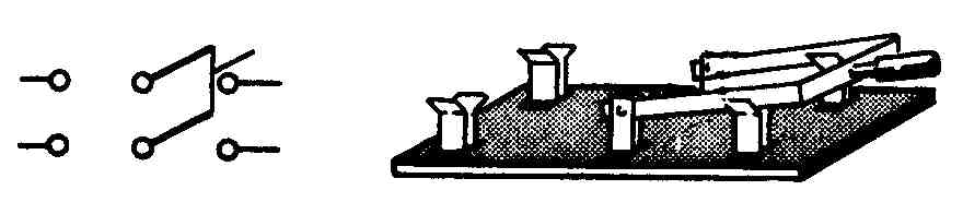
FIG. 6. Double-pole, double-throw switch.
Switches
A wafer switch is shown in FIG. 7. The symbol indicates a 3-pole, 3-circuit switch with two non-shorting and one shorting moving contact.
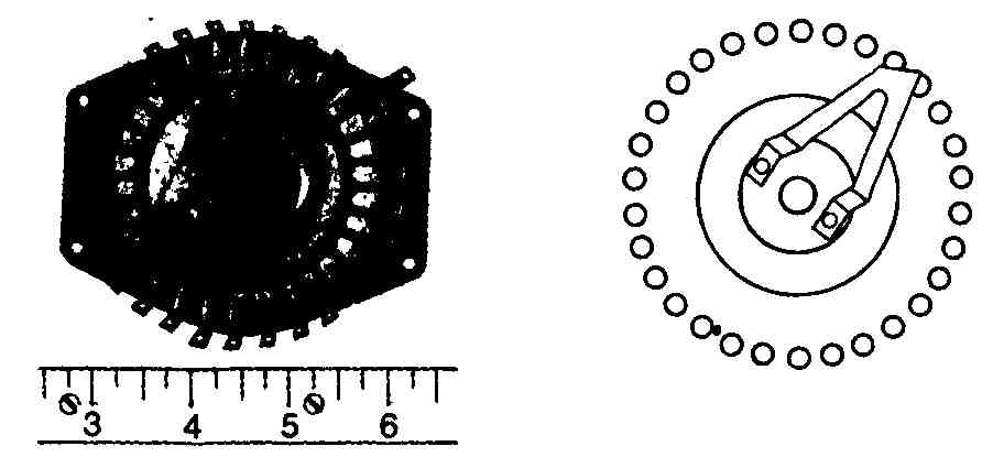
FIG. 7. Wafer switch.
Two types of fuses are illustrated in FIG. 8. There are many types of fuses but they all have the same function to protect a circuit from overloading. The two types of fuses shown are the cartridge type and the screw-in type. When a circuit draws too much current, a metal wire or strip within the fuse melts, interrupting the flow of current. Note that the symbol is the same regardless of fuse type.
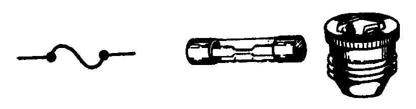
FIG. 8. Fuses.
Resistors
One of the most common electronic components is the resistor. A resistor opposes the flow of electrons. Thus far, only the voltage has been given as a factor influencing the rate of flow of electrons. In some substances, such as glass, rubber and cotton, resistance is great enough to stop the flow completely. Three types of resistors and their symbols are illustrated in FIG. 9.
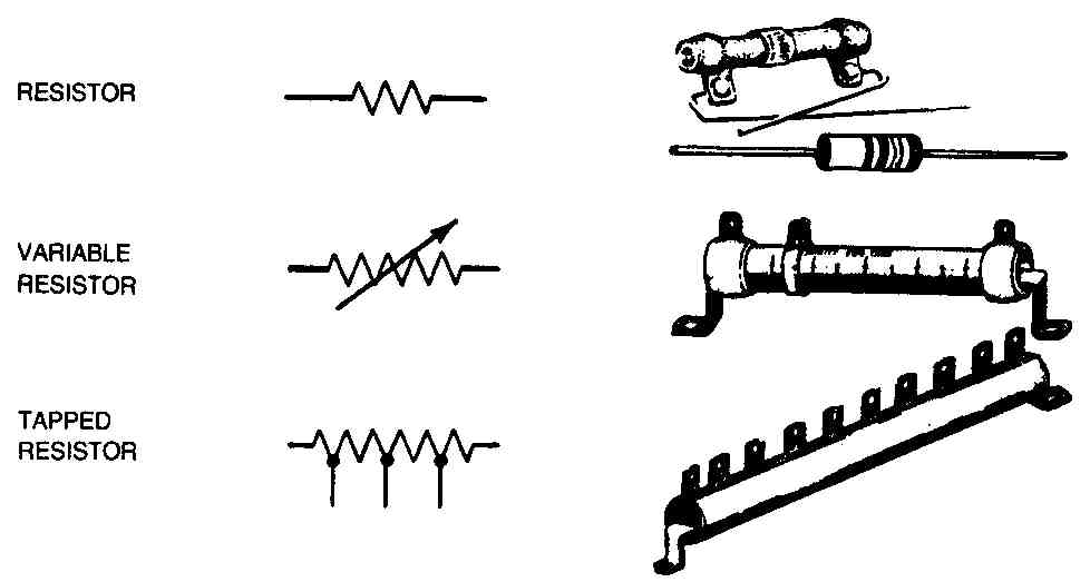
FIG. 9. Resistors.
FIG. 10 illustrates the potentiometer and its symbol. A potentiometer is a variable resistor commonly used as a volume control for radios and television sets.
A rheostat and its symbol are shown in FIG. 11. A rheostat is another form of a variable resistor. It is similar in construction to a potentiometer. A rheostat is almost always wirewound, whereas a potentiometer can be either of wire or carbon.
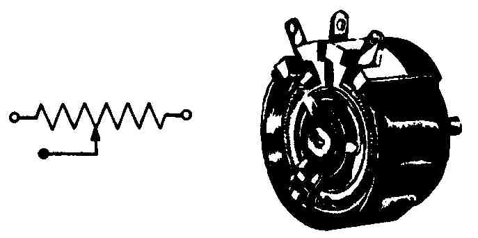
FIG. 10. Potentiometer.
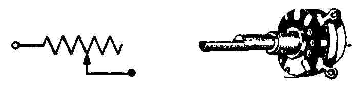
FIG. 11. Rheostat.
Capacitors
Three types of capacitors and their symbols are illustrated in FIG. 12. Capacitors are devices used to store or release electrons as they are needed in the circuit.
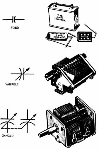
FIG. 12. Capacitors.
Types of Coils
FIG. 13 illustrates two types of inductors and their symbols. One is an air-core, coil type, and the other is an iron core, usually referred to as a choke. Inductors are used to smooth out variations in current flow.
Two types of transformers and their symbols are shown in FIG. 14. Transformers are used to step AC voltage up or down, or to transfer AC voltage from the primary to the secondary.
FIG. 13. Inductors.
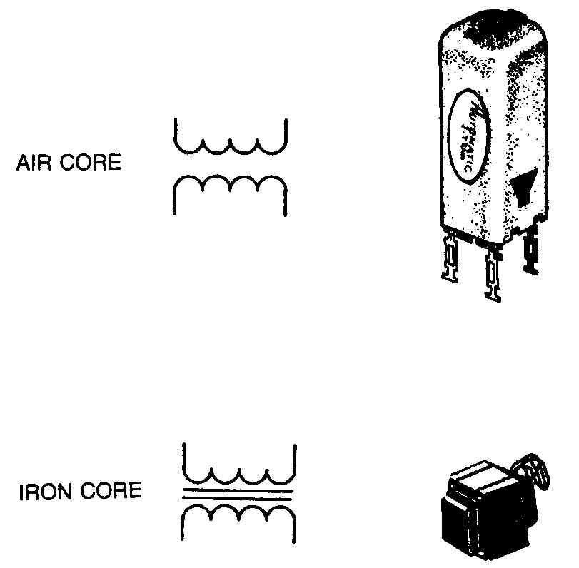
FIG. 14. Transformers.
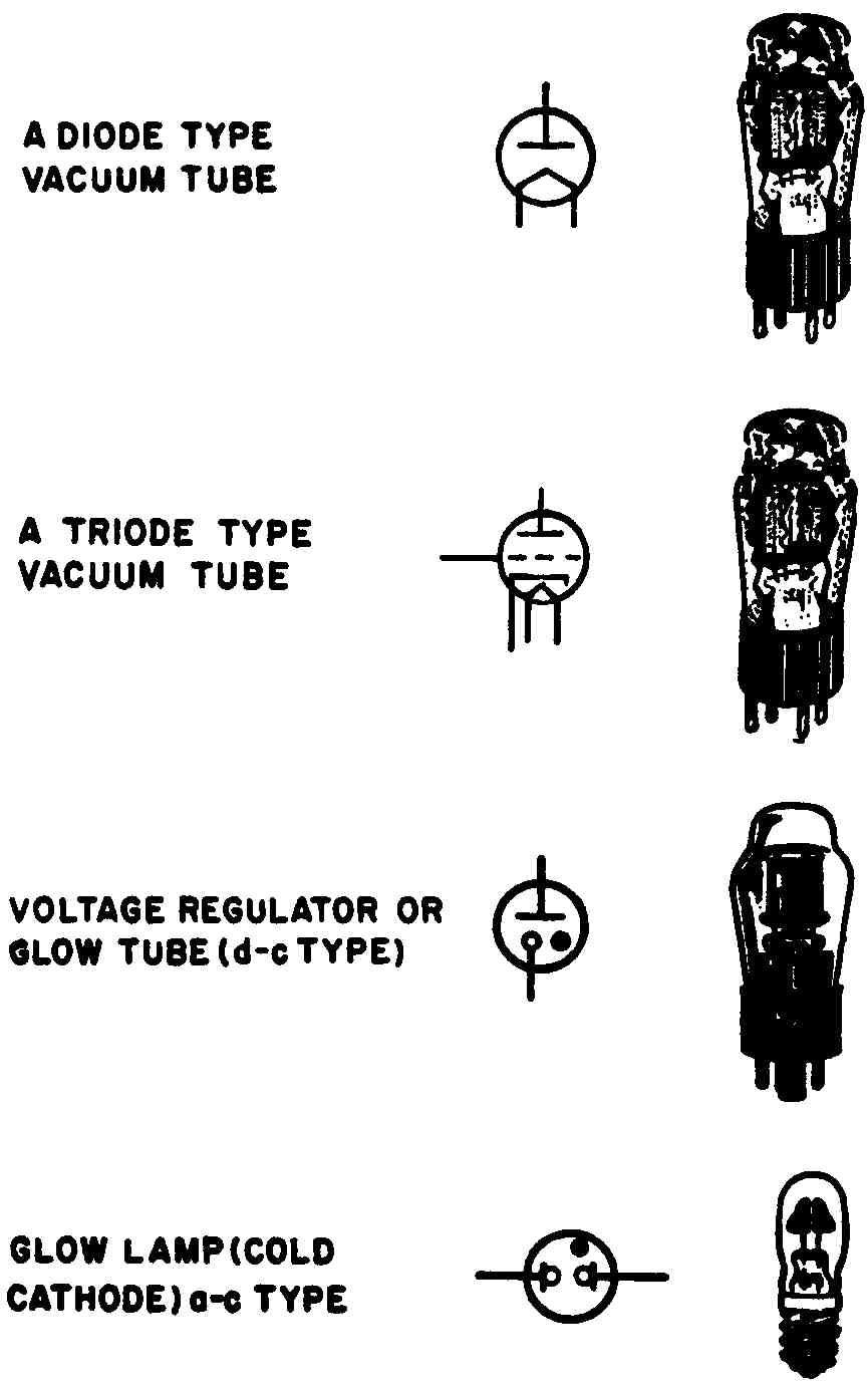
FIG. 15. Vacuum and gas-filled tube types.
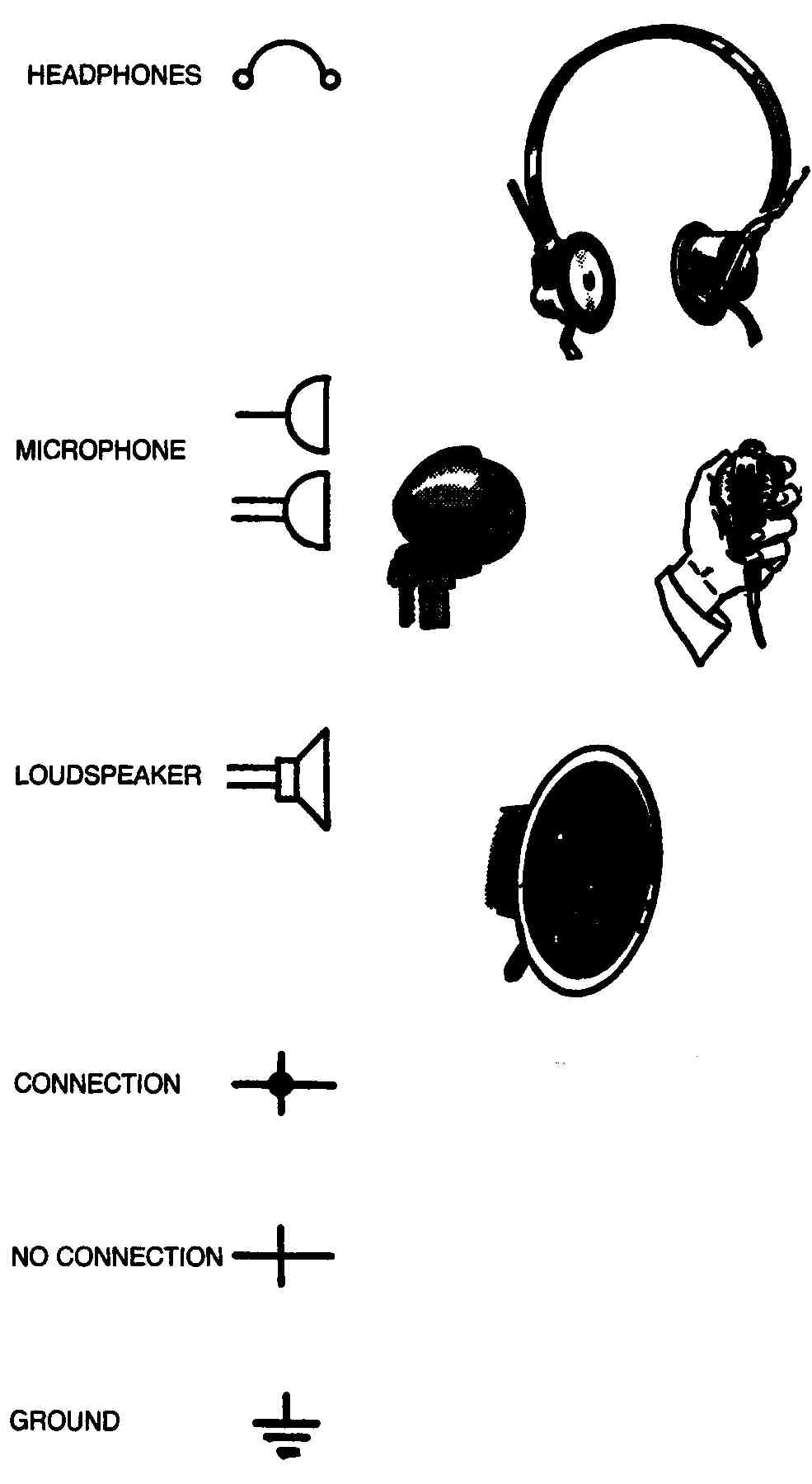
FIG. 16. Symbols and illustrations of ground, wire connections and some common
radio accessories.
Four of the many types of tubes are seen in FIG. 15. Symbols with black dots within the circle indicate that the tube is gas-filled. Other symbols have no black dots within the circle and indicate that the tube is a vacuum tube.
FIG. 16 illustrates the symbols used for ground and wire connections. You are no doubt familiar with headphones, microphones, loudspeakers, wires and ground connections; they need no explanation.