This Section will tell you how to locate and repair a failure of an antique radio as quickly and easily as possible. It will tell you how to check other parts and circuits for damage or indications of possible failure, so that once a set is fixed, it will stay fixed for a while.
The cut-and-try method, or haphazard checking, such as testing the antenna circuit, then the audio circuit, then the IF stages, and soon, wastes time. Certain circuits and components may be missed, and a thorough job cannot be done. The service procedure described next is a logical method of servicing old-time radio sets. By following the procedure, troubles will be located faster, and circuit components will not be overlooked.
A TROUBLESHOOTING METHOD THAT NEVER FAILS
The first operation in overhauling and repairing a set is to thoroughly inspect and clean the set. To accomplish this quickly and avoid any oversights, the operation is divided into the following seven steps. Then preliminary troubleshooting, trouble localization, and trouble isolation follow.
Cleaning and Inspecting Procedure
Removing Plug-In Parts. Remove all plug-in parts, such as tubes, crystals, pilot lamps, and other parts that can be removed without unsoldering wires. Octal tubes can usually be removed from the sockets by merely pulling up on the part in question. In some units, tubes and vibrators are held in place with clamps. To avoid damage to components, release the tension bar on the clamp before attempting to remove the tube or vibrator. Loctal type tubes should be rocked slightly to one side until a click is heard. Then the tube can be lifted out of the socket. Some parts have their leads soldered to a removable terminal strip. These parts should also be removed after loosening the terminal-strip lockscrews, or nuts. Some radio sets have plug-in type RF or IF coils which can be removed by loosening the lockscrews holding the shield cans to the chassis.
Cleaning Set. After loose dirt has been blown from the radio, use a rag soaked in a solvent to clean each part thoroughly, removing any dirt or grease. Be sure, when cleaning the parts, that the wiring is not disturbed; otherwise, when the radio is reassembled and ready to operate, oscillation, degeneration, voltage breakdown, arcover, or distortion may result. As FIG. 1 shows, the old sets had many parts on the chassis, but they were not as tightly packed as parts in modern sets. If it is necessary to move wiring, be sure it is returned to its original position.
Dirt or corrosion that has accumulated on contacts and sockets can cause operating problems. Dirt on the chassis can also hide defects such as the leaky electrolytic capacitor in FIG. 2. Remove any dirt or corrosion that has accumulated on contacts with solvent and sandpaper.
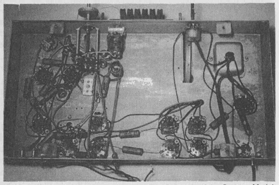
FIG. 1. Bottom view of the sparsely populated chassis of the Sparton Model
1281.
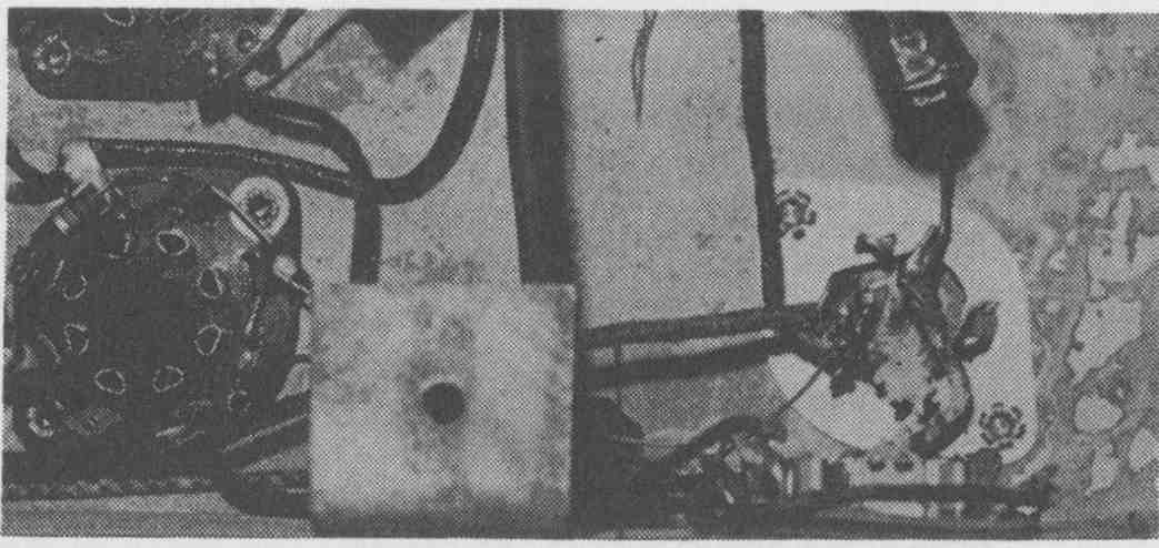
FIG. 2. This filter capacitor was leaky in a literal sense, as the chassis
Corrosion shows.
Corrosion is a common problem in old sets. The amount of corrosion on the chassis in FIG. 3 and the stations selected on the push-button tuner suggested that the radio in question, an old Sparton console, had spent quite a bit of time at the seashore. In a case like this, corrosion of mechanical parts is likely. Remove all corrosion and gum from tuning capacitor shafts, tuning capacitors, and any other mechanical parts in the set.
Visual and Mechanical Inspection. After cleaning the unit, make a thorough examination of all parts and wiring cables, noting the need for replacing any parts found defective. Locating and replacing slightly damaged parts at this time will help to prevent failure of the equipment at some future date. Some of the parts which should be checked are socket contacts, contact springs, gears, tuning capacitors, volume controls, band switches, insulators, sockets for plug-in parts, terminal strips, jacks, loose bolts, rivets, catches, snaps, hinges and nuts. In many instances, noise and intermittent operation are caused by one or more of these defects. In addition to the visual inspection, all operating controls and moveable parts should be inspected for wear and correct operation. Turn each operating control clockwise as far as it will go, then counterclockwise as far as it will go. If binding occurs in either direction, make a note to correct the condition. Any appreciable amount of backlash in tuning-control gear assemblies should also be noted. Troubles of this nature usually require the replacement of a shaft, bushing, or gear assembly and should be corrected as soon as electrical checks have been completed.
Determining Cause of Part Damage. After inspecting the equipment for defective parts, you might find that a capacitor has been shorted, or a resistor burned up, or the insulation on wires burned. In each case, it will be necessary to determine the cause of these failures, since replacing the part may not clear up the trouble but burn up the new part. Only after the cause of trouble has been determined should a new part be installed.
Replacing Defective Parts. When replacing defective parts, be sure that the new parts used are placed in the same position as the part that was removed. If wires were moved, be sure that the wires are returned to the original position; otherwise, the equipment may not operate correctly. Also replace all parts that were noted as defective in the earlier step outlining visual and mechanical inspection.
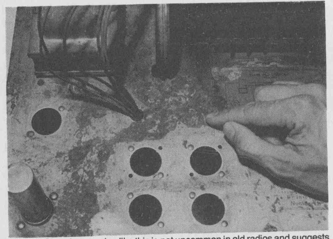
Fig. 3 Chassis corrosion.
Lubrication. Practically all mechanical moving parts used in radio sets require some form of lubrication. After the parts have been cleaned and inspected, lubricate them with a suitable oil or grease ( FIG. 4). Mechanical parts, such as bearings on tuning capacitors, gears, shafts, springs and pivot points, cause noise, improper tuning and intermittent operation of the equipment unless properly lubricated. Cleaning, Inspecting and Testing Plug-In Parts. The plug-in parts, which were removed before the unit was cleaned, must be cleaned, inspected for physical defects and tested for electrical performance before they are reinstalled in the unit. Dirt and grease on the tube prongs can be removed with a solvent. After this is done, it is recommended that fine sandpaper be used to remove any dirt or corrosion that still exists. This is ve important, since the dirt or corrosion that occurs on the tube prongs will cause a high-resistance connection between the tube prongs and the socket contact. After cleaning, check the tubes in a tube checker and replace any found defective. Be sure that cable plugs have clean prongs, and that the cables are not frayed (see FIG. 5). An ohmmeter can be used to check cording continuity. Wiggling the cord at the socket or plug will often reveal intermittent shorts or loose connections. Make sure that all plugs fit snugly into their sockets.
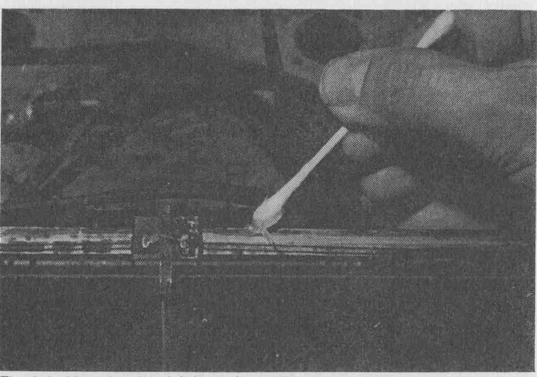
FIG. 4. After cleaning, lubricate the parts.
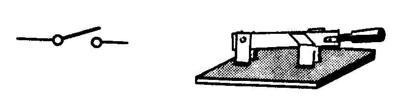
FIG. 5. Check the cable plugs for clean prongs and cables that are not frayed.
PRELIMINARY TROUBLESHOOTING
A logical procedure should be followed in repairing even the simplest piece of equipment. A few preliminary tests often locate the source of trouble without extensive testing with instruments.
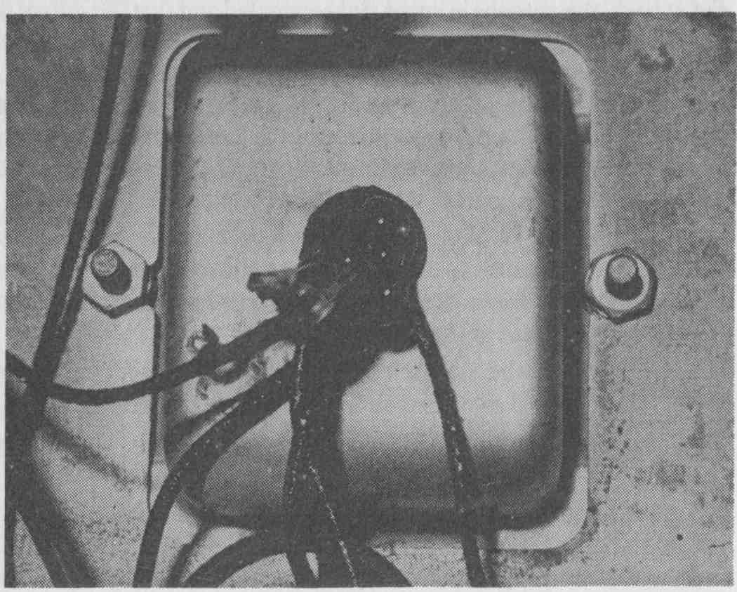
FIG. 6.After warm-up, unusual odors indicate an overheated transformer.
The senses of smell, sight, hearing and touch often localize the source of trouble quickly. After the unit is in operation a few minutes, it may be possible to note unusual odors, such as sealing compound, indicating an overloaded transformer ( FIG. 6); burning paint, usually indicating an overheated resistor; and burning rubber, probably indicating defective insulation. If any unusual odor is detected coming from a part, the trouble may be in that part, or in its associated circuit. Look for smoking parts and sparking. Look for any wax-impregnated paper capacitors that are surrounded by a pool of melted paraffin, usually indicative of a defective capacitor. Hum, scratch noises, and other odd sounds should have a special meaning to the repairman. In general, certain sounds indicate certain types of trouble. For example, hum can indicate a shorted or open filter capacitor. Scratchy noises, heard when the tuning control is moved, can indicate dirty rotor contacts, or foreign particles caught on the plates of the tuning capacitor. Inmost cases, touching the tubes after the unit has been turned on for a few minutes will show whether or not the filaments are heated. If a tube remains cold, the filament of the tube is burned out, or is not getting filament voltage. After the unit has been turned on for a time, turn it off and cautiously touch the different parts, such as resistors, transformers, and capacitors. Notice if these parts are overheated.
CAUTION--To prevent shock, capacitors in high-voltage circuits (such as used in power supplies) should be discharged by placing a low-value resistor across the capacitor after turning off the power.
Finding the Bad Stage
Localization means tracing the trouble to a stage of a section. Before removing the chassis from the cabinet, and prior to disconnecting cables, be sure that power is being supplied, the tubes are not at fault, the antenna is intact and connected and that the defect is not something that can be corrected without disassembling the equipment. For example, if a receiver is completely inoperative, turn the sensitivity and the audio gain controls up to produce maximum output. If only noise is heard, the local oscillator RF stage, or the mixer stage is defective. Check the tubes in these stages. The following tests are used in tracking down trouble:
After the chassis has been removed from the cabinet, check the resistance at the point where the DC from the power supply is applied to the stages, to tell whether there is a short circuit in the power supply.
• Find out which portion of the equipment (RF, IF, or audio) is faulty. Use signal substitution which is discussed shortly.
Note that localizing the trouble to a subchassis or to a portion of the main chassis is also referred to as sectionalization.
• Check the suspected tubes with a tube tester or by substitution.
• Make voltage measurements in the plate, screen-grid and bias lines arid at the tube sockets of the suspected stages.
• Measure resistances at the points where the voltages are abnormal.
• If the complaint is a weak receiver, and other tests fail to detect the troublesome stage, stage-gain measurements must be made. This means feeding a signal of a given strength into the suspected stages and measuring the strength of the signal at the output of those stages and comparing it with that of a good set.
Finding the Bad Tube or Other Part
Isolation means tracing the trouble to a part, such as a capacitor, resistor, transformer, or relay. Isolation is usually done by:
— Using the senses as was instructed in the sections on sectionalization and localization, but in this case it may lead the repairman directly to the defective part.
— Making voltage and resistance measurements at the tube sockets. Examples of this are covered in Section 4.
— Signal substitution and signal tracing as used in localization.
— If a tube is defective, it probably will be located in localization. However, there may be a component part that has short-circuited and, at the same time, has damaged a tube.
— Stage-gain tests may not be necessary at this point, but if they are, the information in localization applies.
— Bridging the suspected part, such as a capacitor, with one known to be good.
SIGNAL SUBSTITUTION
If a receiver is completely inoperative, or one is weak and does not improve when aligned, the trouble can be quickly localized to a stage by signal tracing, or signal substitution. If the receiver is completely inoperative, the signal-substitution method produces quickest results and requires only a signal generator and a set of headphones for testing. This method may not locate the actual defect, but it will indicate the defective stage.
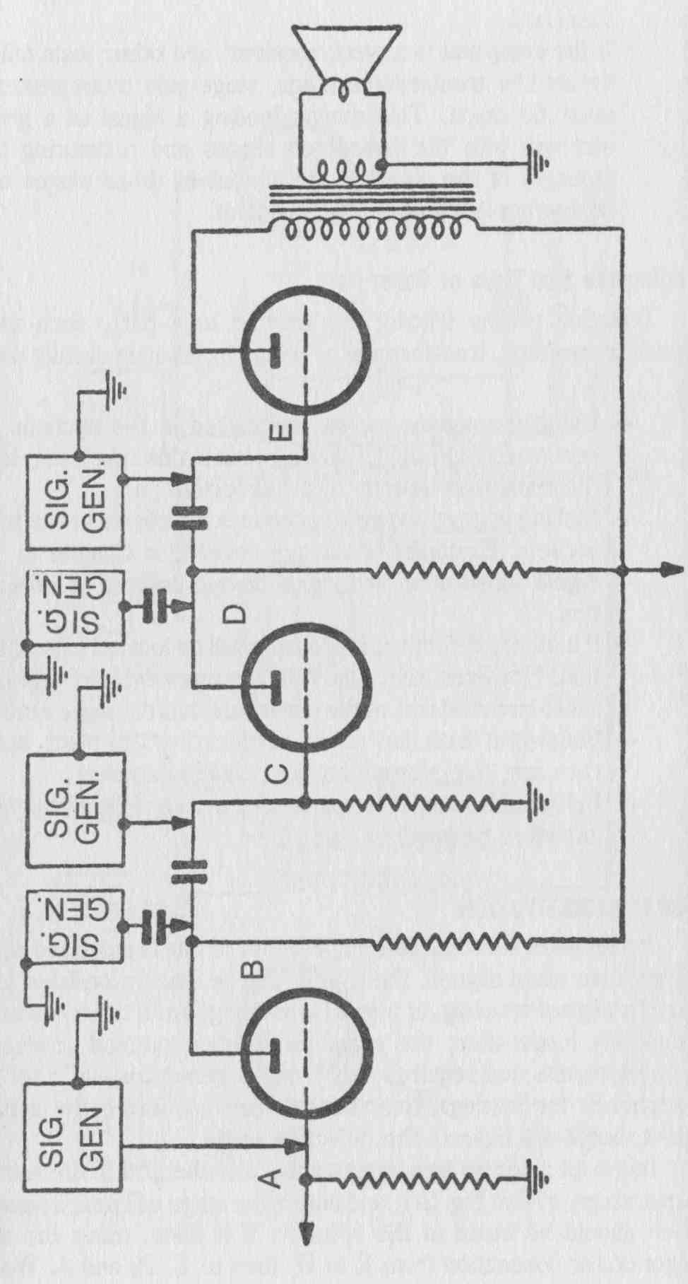
FIG. 7
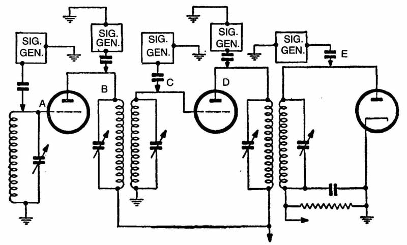
FIG. 8
Inject an AF (audio frequency) signal into the grid of the audio- output stage, at E in FIG. 7, and note if the stage will pass a signal, which should be heard in the speaker. If it does, move the audio generator connection from E to D, then to C, B, and A. Work back to the detector, determining if each stage will pass and amplify the signal. Use a 0.01-uF capacitor in series with the lead to the AF signal source. If the AF stages pass and amplify the signal, check the IF stages.
Inject a modulated IF signal of the correct frequency into the grid or diode plate of the detector, as shown at FIG. 8E and then into the IF stages, as shown at D, C, B, and A, working back to the plate of the mixer and listening for the modulating tone in a headset. Use a 0.001-uF capacitor in series with the lead to the IF signal source. If the IF stages pass the signal, check the mixer and r-f stages (if any).
Inject a modulated RF signal into the grid of the mixer stage, as shown at E in FIG. 9 and note if the signal is heard in the headset when the set is tuned to the signal frequency. If this stage is operating, work back through the r-f stages, as shown at D, C, B, and A, to the antenna terminal.
If any stage fails to pass a signal when using this method, the trouble is localized to that stage, and the individual parts in that stage should be checked for defects.
SIGNAL-TRACING METHOD
A second method of localizing the trouble to a stage is signal tracing. This method is similar to signal substitution, but the procedure starts at the antenna terminal of the receiver, instead of the audio output.
In signal tracing, a signal generator is connected to the antenna terminals of the receiver, and supplies a modulated r-f signal of predetermined amplitude. This signal can then be followed or traced through the various stages of the receiver by connecting an indicating device, described in the following paragraph, first to the input, and then to the output, of each succeeding stage. The point where the signal disappears will indicate the defective stage, and the individual parts within that stage should be checked for defects.
Indicator units used in signal tracing should be of a type suitable for the circuit under test. The audio-amplifier stages require an indicator such as an output meter, speaker, or oscilloscope. Amplifiers operating at radio frequencies require a test instrument that will give an indication at radio frequencies, such as vacuum-tube voltmeters, RF oscilloscopes, detectors with an audio amplifier, or special signal-tracing equipment.
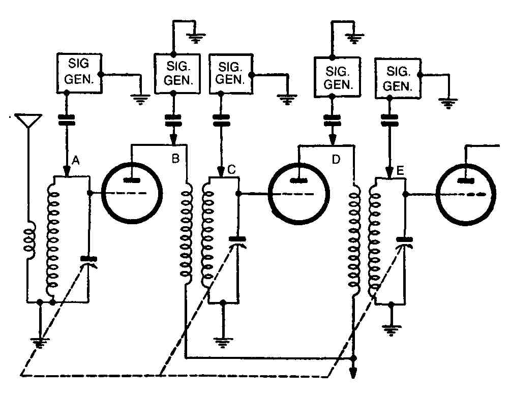
FIG. 9. Typical RF amplifier, showing signal-substitution points.
In receivers which operate but do not meet sensitivity specifications, the signal tracing method is used most often to measure the relative gain of the signal through each successive stage of the receiver. Included in the service instructions for a receiver there may be a signal tracing chart which contains information on where to apply the input signal, what amplitude the input signal should be, where to connect the indicating device, and what indication should be obtained if the stage is operating properly. With this information, the trouble can be quickly localized to a stage. Then the individual parts within the stage should be checked for defects.
The signal substitution method can also be used to localize trouble in weak receivers if calibrated audio and RF signal generators are used to inject a signal of the frequency and amplitude specified on the signal tracing chart.
CIRCUIT-DISTURBANCE METHOD
Usually, in receivers that are completely inoperative, the trouble can be localized to a stage in the shortest possible time by the signal-substitution method or the circuit-disturbance method.
The circuit-disturbance test is similar to signal substitution. Turn the receiver on and allow sufficient time for the tubes to warm up. Set the volume control for maximum gain and touch the control grid of the output tube with a coin, key, or other metallic object ( FIG. 10). A click or loud hum should be heard in the headset if the output stage is operating properly. If a click or hum is heard when the output stage is disturbed, follow back through the audio, IF and RF stages, listening for clicks or hum when the grids are touched. When a point is reached where no clicks are heard, the trouble is between this point and the point at which clicks were last heard, and the individual parts within this section should be checked for defects.
STAGE-MUTING METHOD
Hum, oscillation and noise are common troubles which are sometimes very difficult to locate. The most helpful procedure to follow in trying to determine the cause of one of these troubles is to first localize the trouble to a stage. An efficient and simple method is called stage muting. In using this method, the grid of a stage is effectively shorted to the chassis with a capacitor of approximately 0.25uF. Thus, signals originating further back in the receiver cannot affect or pass this stage. Starting at the output stage, short the grid to the chassis with a capacitor. If the hum or noise continues, the cause must be in the power supply or the output stage. If the hum or noise stops, it is originating at some point preceding this stage. Work back through the set, shorting each grid to chassis in turn, until a grid is reached where the hum or noise does not stop. The point where the hum or noise originates will be between that grid and the preceding grid that was shorted to the chassis.
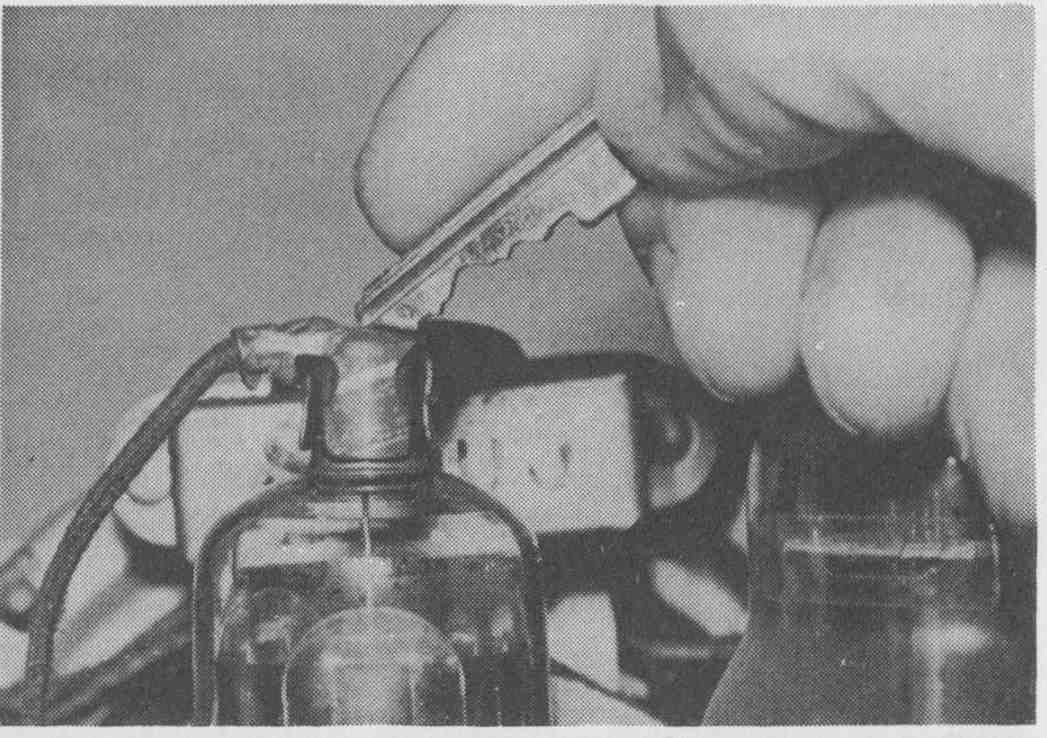
FIG. 10. Perform the circuit-disturbance test by touching the control grid
of an output tube with a key.
LOCAUZING INTERMITTENT TROUBLES
Conditions of intermittent operation and intermittent noise are probably the most difficult to localize. In many instances it will be necessary to use more than one of the previously discussed methods to localize the trouble to a stage. In some units, intermittent operation or noise occurs only when the unit is cold; in others, only when the unit is hot, or when a signal is applied. Whenever possible, attempt to duplicate the condition under which the trouble is noticeable. Conditions of cold can be duplicated by placing the unit in a refrigerator, or out doors, for a period of time before testing. Conditions of heat can be duplicated by placing the unit in an oven, or by operating the unit for a period of time in a confined area, such as under a cover or in a box. In instances where noise is present only when a signal is applied, tune the signal generator and receiver to the low-frequency end of the band and apply an unmodulated RF signal of sufficient strength to cause the receiver to be microphonic. Then gently tap various components to localize the noise to a stage, section, or part.