A television performs three tasks: it shows a picture (video), it produces the sounds (audio) that accompany the picture, and it synchronizes the picture it produces with the picture that is transmitted. A picture without sound is unacceptable, and sound without a picture is like watching a radio. If the picture on the screen is not synchronized with the picture that is transmitted, the resulting picture is chaotic. This section describes the basic operation of a television, and how it receives signals, converts signals, and produces both picture and sound.
How TV Produces a Picture and Sound
A picture is a series of tiny squares. Using black and white as an example, the squares range from black to white with many gray tones in between to add definition. When you magnify a black and white photograph, the small squares that define the picture become apparent, as shown in FIG. 1.
The signal a television station transmits also is made up of tiny squares of light and the spaces between the squares. You can see the tiny squares on the television screen when you tune to an unused channel. At the television station, the tiny squares that define a picture are converted to electrical signals. Accompanying the electrical signals is all of the information about the squares of light, including their positions and their intensity. This information is used by the receiver that converts the signals to a picture to duplicate the transmitted picture. The more tiny squares there are in a picture, the better the picture quality or resolution.
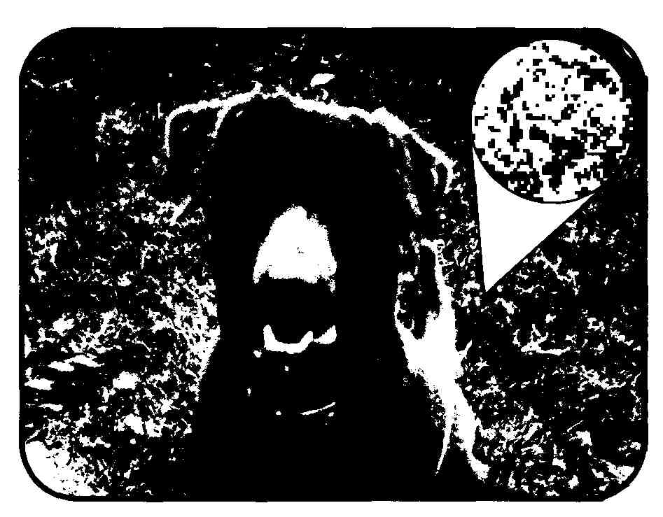
FIG. 1. The circle shows a close-up of the tiny squares that make up a TV
picture.
Also, the television receiver must be able to stay in step with the television station’s transmitter. The television camera scans a scene much like a person scans a page of printed material. Starting at the top-left corner, a per son scans the first line left to right. Then, when the first line is complete, the person’s eye moves down one line and back to the left side of the page. This pattern continues until the page is finished.
To ensure that the receiver stays in step with the transmitter and duplicates the transmitter’s left-to-right and top-to-bottom scanning pattern, a series of signals or timing signals called synchronizing (sync) signals is sent by the transmitter, along with the picture and sound signals. Using the sync signals, the receiver can stay in step with the camera’s scanning pattern. Sync signals can be divided into two sets of instructions. The right-to-left instructions are called horizontal-sync signals. The bottom-to-top instructions are called vertical-sync signals. If there are problems with the sync signals, the picture on the television appears to flicker, tear horizontally, or roll vertically.
Reducing flicker is discussed in the next section. Horizontal tearing and vertical rolling are discussed in the section Processing the Sync Signals, later in this section.
Video Basics
There are 525 horizontal lines in one television picture (frame), with 285 squares of information on each line. In the U.S., a television station transmits 30 complete frames every second. Transmitting only 30 frames per second causes the picture to appear to flicker. This flickering is reduced by interlacing the 525 horizontal lines. Starting at the top of the screen, the electron gun in the picture tube (cathode ray tube or CRT) evenly scans 262+ lines down the screen, shown as solid lines in FIG. 2. Then, the electron gun goes back to the top-left of the screen and scans another 262+ lines between the first lines. The second set of scan lines are shown as dashed lines in FIG. 2. Interlacing the lines reduces the flickering and produces much the same effect as 60 complete pictures-per-second.
A set of 262+ lines is called a field. It takes a set of two fields to produce one complete frame.
- - —
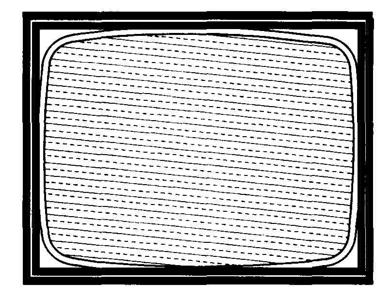
FIG. 2. Interlaced scanning of the horizontal lines of a TV picture.
If the television is not producing a picture, it produces a scanning pattern. This pattern, called a scanning raster or snow, appears as a series of horizontal white tines even though you cannot see the defined lines. The snow pattern is important to show that radio frequency signals are being received. The radio frequency signals carry the video, audio and sync signals. You can reproduce a scanning raster by disconnecting the television’s antenna and tuning to an unused channel. If the snow pattern is absent, there is a problem with one of the early stages of reception, such as the tuner or the IF stages.
In addition to the blanking pulses used to blank retrace lines at the end of the sweep cycle, the newer televisions have a built-in blanking circuit which blanks the raster if there is no signal. You can see the retrace lines if you maximize the brightness. The scanning raster is a troubleshooting tool that will be described later in this guide.
In addition to the scanning raster, a camera must also determine the amount of red, green and blue in the original picture, and the brightness of each square that makes up the picture. When this information is transmitted to the receiver, the receiver must be able to reproduce the original picture by combining correct proportions of red, green and blue, and by reproducing the brightness of each square that defines the picture. All of this picture information is sent to the receiver in video signals.
Using the controls on the television, it is possible to adjust the brightness and contrast to washout or intensify the color of the picture. Even slight adjustments can cause light areas in a picture to lose detail and the dark areas to appear lighter. These problems can be solved easily using the television’s controls. Other problems with the color and brightness are not so easy to identify. Later Sections provide more information about analyzing the color and brightness of the picture produced by the television when troubleshooting picture problems.
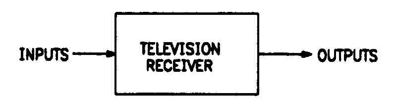
FIG. 3. A simple block diagram that shows a black box containing circuit
information.
Sound Basics
Television sound (audio) is transmitted as FM signals because FM signals are less noisy than AM signals. At the television station, the FM audio signals are combined with the video transmission. Section 6 describes how the sound system works for monaural (mono) as well as stereo sound, as well as how to use the television’s sound to locate troubles in a receiver.
Using a Block Diagram
Television manuals and repair documentation usually include block diagrams. These diagrams break down the entire process of receiving signals, con- veiling signals, and producing picture and sound in a chart format that makes it easy to follow the sequence of the processes called stages. Thus, block diagrams can be a useful troubleshooting tool, even though they do not replace the more complex schematics that we will discuss later in the guide.
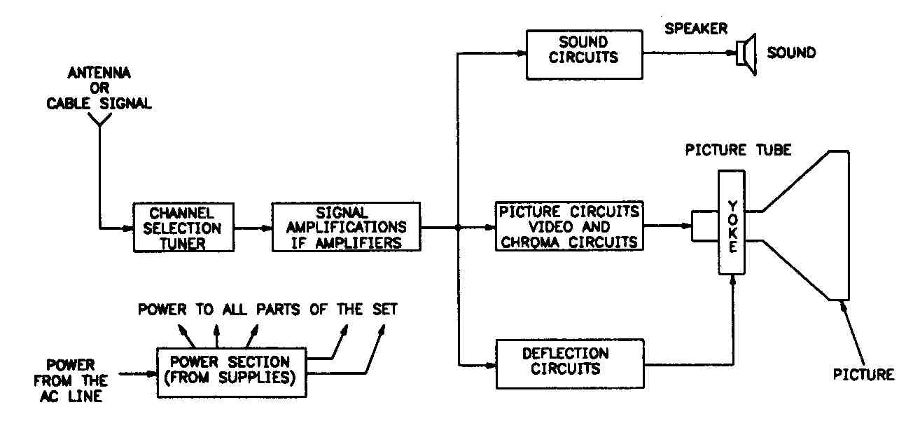
FIG. 4. A functional block diagram showing the basic steps in the process
of converting a signal into televised information.
Block diagrams can show high-level views of a process or complex circuit in formation. The simplest version of a block diagram is a black box diagram, shown in FIG. 3, in which there is an input and an output, but the process of receiving the signal, converting the signal, and producing picture and sound appears as a black box providing no details.
The block diagram shown in FIG. 4 is somewhat more complex. It shows that the television is receiving the appropriate power so that it can complete the required processes. The diagram also shows the basic steps in the process of receiving the signal, converting the signal, and producing the picture and sound, as well as the sequence in which the process takes place.
The antenna receives the signal from the television station. When the television’s tuner selects the channel assigned to the television station’s transmitting frequency, the television’s intermediate-frequency (IF) amplifiers increase the selected signal. Then, the signal is split into the three parts: audio signal, video signal and sync signal. These three signals are processed simultaneously.
FIG. 5 is a more typical block diagram. This diagram shows all of the processes that take place in the television, from receiving the signal from the television station to producing the video and audio. This diagram makes it easy to trace the signal through each stage of the process.
The following sections describe each stage in the block diagram. Refer to the block diagram in FIG. 5 while reading through the sections.
Receiving the Signal
Even though the antenna is separate from the television and is often treated as an independent stage, electrically it is really part of the television’s tuner. The antenna receives the RF (radio frequency) signal from the television station and passes the signal to the tuner. All antennas do not receive all television channels. Some antennas work only with VHF channels (channels 2 through 13), and others work only with UHF channels (channels 14 through 83). There also are antennas that receive all channels, as well as some that are designed for only one channel.
Cable companies access signals through a satellite dish. Also, many people now access the television through satellites directly. The signal received from the satellite, whether at a cable company or directly, goes to an amplifier that lowers the frequency to the television frequency range. Then the signals are passed through a cable to the television. Cable access signals are typically stronger and cleaner than antenna signals.
Each television station transmits at a different frequency. The unit of measurement for a television frequency is megahertz (MHz). The frequencies for the VHF channels are 54 MHz through 216 MHz. The frequencies for the UHF channels are 470 MHz through 890 MHz. The tuner’s job is to select a signal at an assigned frequency (channel) from all of the available signals, both weak and strong, then process the signal so that it can be used by the IF (intermediate frequency) amplifiers. IF amplifiers are described in the next section, Increasing the Signal’s Strength.
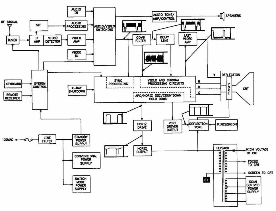
FIG. 5. A typical block diagram, tracing the signal through each stage of
video and audio production process.
After an RF signal is processed, the output is the IF frequency that contains the composite video, audio and sync signals. FIG. 6 shows the waveform of the IF signal.
1. 39.75 MHz—Adjacent channel’s video carrier.
2. 41.25 MHz—Audio carrier.
3. 41.67 to 42.67 MHz—Color carrier.
4. 45.75 MHz—Video carrier.
5. 47.25 MHz—Adjacent channel’s audio carrier.
The IF signal is sent to the IF amplifiers where its strength is adjusted. If all signals were of equal strength, this adjustment would not be necessary. However, all signals are not of equal strength. So, the adjustment is made by a control signal called the automatic gain control (AGC). The AGC is de scribed in the next section.
Increasing the Signal’s Strength
Under normal conditions, the signal from the tuner is not strong enough to operate the picture and sound. Therefore, the signal strength has to be increased. The IF amplifiers, shown in FIG. 7, amplify the signal strength.
The AGC, shown in FIG. 7, monitors the average strength of the sync signals. The AGC adjusts the signal’s strength by increasing or decreasing a control voltage to the tuner and the IF amplifiers. If the voltage level of the sync signals is too low, the AGC increases the control voltage to the tuner and the IF amplifiers. If the voltage level of the sync signals is too high, the AGC decreases the control voltage to the tuner and the IF amplifiers.
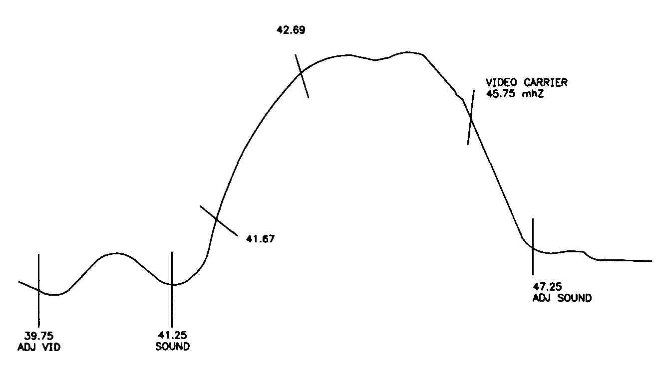
FIG. 6. The waveform of an IF signal.
Separating Video and Audio
After the signal is amplified sufficiently in the IF amplifiers, the signal is passed to the video detector, shown in FIG. 8. The video detector is in the integrated circuit (IC) that is part of the video IF amplifier and converts the amplified signal from the IF amplifiers and separates the signal into two types:
1. The composite video, which is an AM signal (30 Hz to 4.2 MHz) containing the video and the sync signals.
2. The sound IF, which is an FM signal (4.5 MHz).
Then, the composite video signal and the sound IF signal are sent to the video amplifiers.
Processing the Video
The video amplifiers perform several tasks. First, the video amplifiers increase the signal from the video detector. Then, the sound IF signal and sync signals are separated from the picture information. The sound IF signal is sent to the sound IF amplifier. The sync signals are sent to the sync separator.
The video signal is amplified more, then sent to the video processing circuit. The contrast control, located in the video processing circuit, controls the amount of video sent to the CRT, like the volume control adjusts the audio level sent to the speakers. In color televisions, the color signals are separated at this point and sent to the luminance and chroma processing stage. Color processing is discussed later in Section 5.
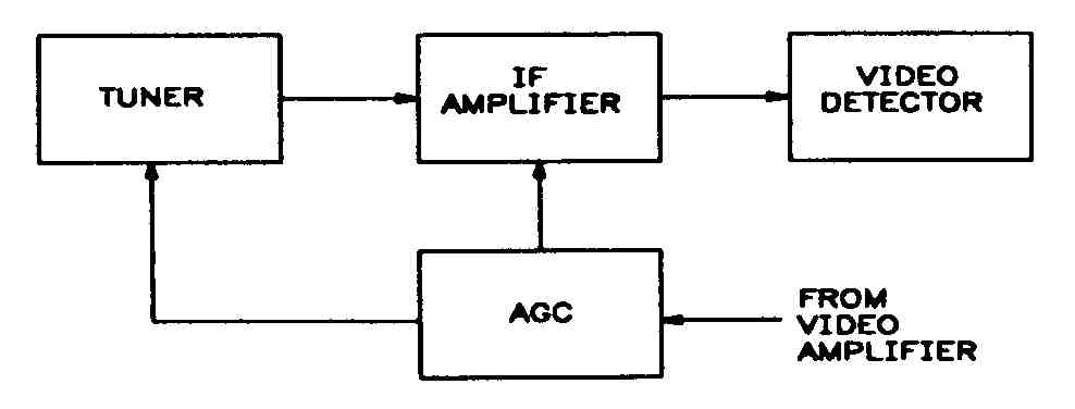
FIG. 7. Block diagram of an IF amplifier and AGC.
Processing the Audio
The audio processing system, shown in FIG. 9, receives an audio signal from the video amplifier and processes it so that the speakers can produce the sound that accompanies the picture.
The sound IF amplifier increases the FM audio signal before it is sent to the sound detector. Before the audio signal can be sent to the speaker, it must be separated from the sound carrier by the sound detector. The output from the sound detector is an electrical audio signal that must be amplified again by the audio amplifier before it can be heard through the speaker. After the sound completes its trip through the sound processing system, the speaker converts the electrical audio signal to audible sound.
The volume control and tone control are in the audio amplifier stage.
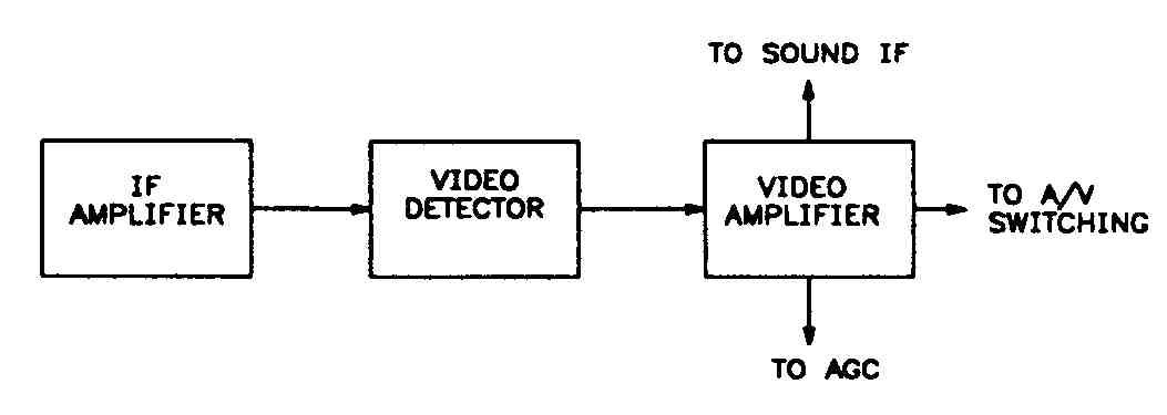
Fig. 8
Processing the Sync Signals
Remember that the sync signals are sent by the television station along with the audio and video signals, and ensure that the picture that appears on the screen is synchronized with the picture that was transmitted. Loss of sync signals can cause many problems, from no video to partial picture loss and tearing.
The sync amplifier increases the sync to the required level, and makes sure the correct video timing and placement information is present. The sync separator separates the sync signals into horizontal sync signals and vertical sync signals. The horizontal sync signals control the starting time of the left-to- right lines on the screen. The vertical sync signals control the starting time of the picture from the top-left corner of the screen. As mentioned previously, problems with the sync signal processing can cause vertical rolling or horizontal tearing.
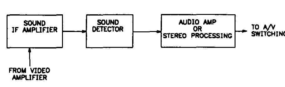
FIG. 9. Block diagram of a sound IF amplifier sound detector and audio amplifier
Horizontal Sync Signals
The horizontal sync signals are sent to the automatic phase control (APC), shown in FIG. 10. The rate at which the horizontal output operates deter mines the actual rate at which the picture is scanned to the screen. The picture scan rate must be synchronized with the rate at which the picture is transmitted. To make sure the horizontal sync signal is synchronized with the sync signals, the output is compared to the sync signals by the APC.
After the comparison is made, any adjustments to the horizontal signal are made by the horizontal oscillator. If the rate is too slow, the APC causes the oscillator to speed up, which produces a faster horizontal sync signal rate. If the rate is too fast, the APC causes the oscillator slow down, which produces a slower horizontal signal rate. In this way, the horizontal oscillator produces a horizontal scan signal that is correctly synchronized with the sync signals. The horizontal hold control is in the horizontal oscillator. Next, the horizontal signal is sent to the horizontal output stage.
The horizontal output stage is a powerful signal amplifier, which is turned on and off by the horizontal oscillator. The main job of the horizontal output stage is to provide adequate horizontal scan power to the deflection yoke, an electrical assembly attached to the neck of the CRT which controls the horizontal and vertical scan that produces the picture. The output signal causes the electron beam in the CRT to scan horizontally at a rate that is synchronized with the sync signal—15,750 times every second—to produce one frame of the video. A considerable amount of power is needed to move the electron gun so rapidly. The television’s horizontal output stage, also shown in FIG. 10, provides the required signal to generate the high voltage needed by the CRT.
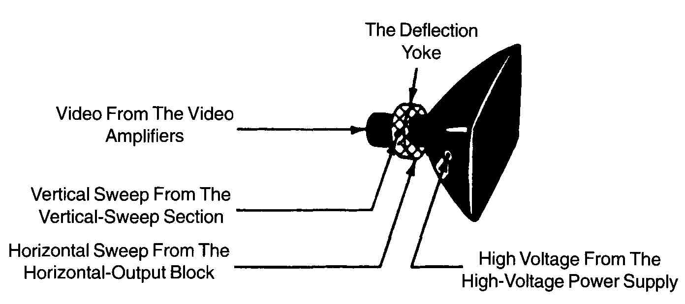
FIG. 10. A horizontal oscillator and output, APC, and a high-voltage power
supply.
The vertical sync signals are sent to the vertical oscillator section. Then, after amplification, the signal is sent to the vertical deflection yoke. The output signal causes the electron beam in the CRT to scan vertically at a rate that is synchronized with the sync signals. The vertical hold control, and the picture height and linearity controls are in the television’s vertical scan stage.
The CRT, shown in FIG. 11, receives input from several sources in the television. It receives the voltage necessary to operate the electron gun from the high-voltage power supply which is in the flyback transformer stage. The video signals come from the video amplifiers. The horizontal and vertical scan, processed from the sync signals, provide the timing and location information for the video. The video signal provides the chrominance (color) for color televisions, and luminance (intensity) for both color and black-and-white televisions.
From these inputs, the CRT reproduces the picture transmitted by the television station. If all parts of the television work properly, the reproduced picture is synchronized with the transmitted picture, and the reproduced picture is high quality, without flickering or distortions. However, all parts of the television do not always work properly, and a low quality reproduced picture or no picture can result. The remainder of this guide describes troubleshooting methods that can help you locate and repair problems that occur.
FIG. 11. A CRT diagram.
Quiz:
1. Define the following terms:
a. Antenna
b. Audio
c. Automatic phase control (APC)
d. Automatic gain control (AGC)
e. Deflection yoke
f. Electron gun
g. Frame
h. Horizontal oscillator
i. Horizontal sync signals
j. IF amplifier
k. Interlacing
l. Sync signals
m. Tuner
n. Vertical sync signals
o. Video
2. How many horizontal lines does it take to produce one frame?
3. What is the purpose of the sync separator?
4. How is flickering reduced in a picture?
5. What are the two functions of the video amplifier?
6. What are the three types of signals transmitted over a carrier signal from the television station?
7. Why are FM signals used to transmit audio information?
8. Why is a block diagram a useful troubleshooting tool?
Key:
1.a. A device that collects the composite RF signal transmitted from the television station.
1.b. Any sound, mechanical or electrical, that can be heard. Audio is normally 20 Hz to 20,000 Hz.
1.c. Holding the horizontal oscillator in step (phase) with the horizontal sync signal.
1.d. Regulating the receiver’s overall amplification (gain) to produce a constant output from variable input.
1.e. An electrical assembly attached to the neck of the CR1 which controls the horizontal and vertical scan that produces the picture.
1.f. An assembly in the CRT that emits a small electron beam.
1.g. One television picture in which there are 525 horizontal lines.
1.h. An oscillator that makes adjustments to the horizontal sync signal.
1.i. Right-to-left instructions that control the horizontal scanning on the screen.
1.j. Amplifier that increases the signal strength from the tuner.
1.k. A method of scanning the 525 horizontal lines in two successive fields of 262+ lines to reduce picture flicker. After the first field is scanned, the lines from the second field are scanned between the lines of the first field.
1.l. A series of signals or timing signals that synchronize the picture scanned on the screen with the picture transmitted from the television station.
1.m. The circuit that selects the channel assigned to the television station’s transmitting frequency.
1.n. Bottom-to-top instructions that control vertical scanning on the screen.
1.o. Picture signals that are used to produce the picture on the screen.
2. 525.
3. Circuit that separates the sync signals into horizontal sync signals and vertical sync signals.
4. The 525 horizontal scan lines are interlaced in two groups of 262+ fields.
5. Amplifies the signal from the video detector and separates the sound IF signal and the sync signals from the picture information.
6. Composite video, audio and sync signals.
7. FM signals are less noisy than AM signals.
8. They show high-level views of a process or complex circuit information.