The importance of safety can never be stressed enough. The leading manufacturers include safety information and specific warnings with the televisions when they ship them from the factory. However, most of this information is designed as general operating guidelines for consumer consumption, not for technical troubleshooting and repair.
This Section discusses specific safety guidelines for technicians who work on integrated circuits, power supplies and high-voltage circuits. If a technician does not follow the appropriate safety guidelines, it can be hazardous to the technician and to the consumer whose television the technician is repairing.
Only qualified service technicians who are familiar with safety checks and guidelines should perform service work. Before replacing parts, disconnect the power source to protect yourself and electrostatically sensitive parts. Do not attempt to modify any circuit unless directed to do so by the television’s manufacturer.
General Guidelines to Follow Before Returning the Repaired Receiver
Perform a final safety check before returning a receiver to the customer:
1. Check the repaired areas for poorly soldered connections. Make sure that solder joints are ball-shaped, shiny and smooth, not sharp. If the solder is grainy and dull, there is an air bubble in the center of the solder. This air bubble will cause a bad solder joint.
2. Check the entire circuit board for solder splashes.
3. Check the inner board wiring for wires that are pinched or frayed, or that touch any high-wattage resistors.
4. Check that all control knobs, shields, covers, grounds and mounting hardware have been replaced.
5. Replace all insulators and restore properly dressed leads.
6. Check all leads for strain or tension, especially those near any metal parts.
7. Make sure that all insulation and isolation materials are replaced.
8. Remove any loose or foreign particles from the circuit board and the cabinet.
9. Make sure that all hardware items have been reinstalled according to the factory specifications.
10. Make sure that all replacement parts meet safety requirements and factory specifications for the specific television brand and model.
Testing for Cold Leakage Current in Receivers with Isolated Ground
To test for cold leakage current:
1. Unplug the television’s AC power cord.
2. Connect a jumper across the power cord’s plug prongs.
3. Turn on the power switch (if applicable).
4. Using an ohmmeter, measure the resistance between the jumped AC plug and any exposed metal cabinet parts, such as the antenna terminals, control shafts or handle brackets.
5. Read the ohmmeter. Exposed metal parts with a return path should measure between 1 megohms and 5.2 megohms. Exposed metal parts without a return path must measure infinity.
Testing for Hot Leakage Current
To test for hot leakage current:
1. Plug the television’s AC power cord into a 120V AC outlet.
2. Using an AC voltmeter or a volt-ohmmeter with a sensitivity of at least 5000 ohms per volt, measure the voltage across the resistor, as shown in FIG. 1. Check all exposed metal parts and measure the voltage at each point.
3. Using a 1500 ohm, 10W resistor in parallel with a .15 mF capacitor, connect one clip to any exposed metal part on the receiver and the other clip to a good earth ground.
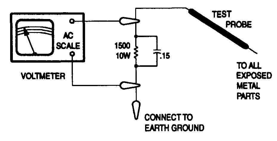
FIG. 1. A voltmeter measuring voltage across a resistor
4. Note the meter’s AC voltage drop across the resistor. Voltage measurements should not exceed .75V AC, 500 mA. Any value that exceeds this limit constitutes a potential shock hazard and must be corrected.
5. If the AC plug is not polarized, reverse the AC plug and repeat Steps 4 and 5.
Avoiding Electrical Shocks When Servicing High-Voltage Circuits and CRTs
Use extreme caution when servicing high-voltage circuits:
1. Perform the tests for cold and hot current leakage.
2. Always use tools that have been approved for use on electrical circuits. Also use rubber pads on the work surface and on the floor beneath the work surface.
3. Always wear shatterproof goggles when handling the CR1 to protect the eyes in case of implosion.
4. Read thoroughly any instructions and procedures that address high voltage.
5. Make sure that all test equipment is in good repair, is calibrated properly and works correctly. Keep an accurate high-voltage meter available at all times, and check the meter’s calibration frequently.
6. When servicing the receiver, use an isolation transformer between the line cord and the power receptacle.
7. Discharge the CRT before removing it from the chassis. To discharge static high voltage, connect a 10 ohm, 15W resistor in series with a test lead between the chassis ground and the CRT’s anode lead. Do not lift the CR1 by the neck.
8. When servicing a receiver, check the voltage at various brightness levels to make sure the receiver is regulating properly.
9. Use plastic knobs and bushings to isolate metal parts, and replace missing or broken insulators.
10. Make sure that the power cords and all leads are not frayed and do not have exposed wires. Also, make sure the power cord is unplugged before you touch components, such as the flyback transformer or horizontal output transistor.
11. Make sure that all antenna leads are isolated from the chassis using capacitors and resistors.
12. Replace any part that is deteriorated.
13. Discharge the filter capacitors before checking voltages in the power circuits.
14. Connect the lead of any high-voltage probe to a good earth ground.
15. Avoid voltage arcing (corona) that might result from pointed solder joints or frayed wires. Voltage arcing can destroy the solid-state circuits in the receiver, damage the CAT, and cause fires.
16. Avoid static charge buildup by using a grounding wrist strap or a static discharge rug.
Avoiding X-Ray Radiation and High-Voltage Limits
X-ray radiation is produced by excessively high voltage. In solid-state receivers and monitors, the CRT is the only potential source of X-rays. In some receivers, many electrical and mechanical components have safety-related characteristics which are not detectable by visual inspection. These components, such as the high-voltage rectifier and the shunt regulator tube in older televisions, are identified by a number on the schematic and on the parts list:
1. Read thoroughly any instructions and procedures that address X ray radiation.
2. Use a correctly calibrated high-voltage meter to test for excessive voltage. An example is shown in FIG. 2.
3. Keep high-voltage values at the rated value and no higher. Do not depend on protection circuits to keep voltage at the rated value.
Excessively high voltage may cause X-ray radiation or failure of the associated components.
4. Discharge the CAT before working on it.
5. When troubleshooting a receiver with excessively high voltage, avoid close contact with the CRT and do not operate the receiver longer than is necessary.
6. To locate the cause of excessively high voltage, use a variable AC transformer, shown in FIG. 3, to regulate voltage.
7. Use only equivalent replacement parts when replacing components that may be a source of X-ray radiation.
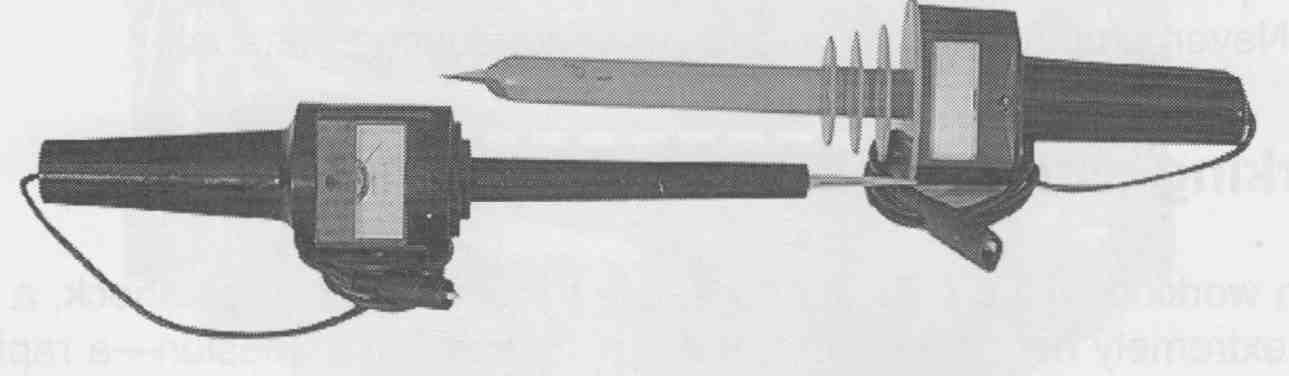
FIG. 2. A high-voltage meter
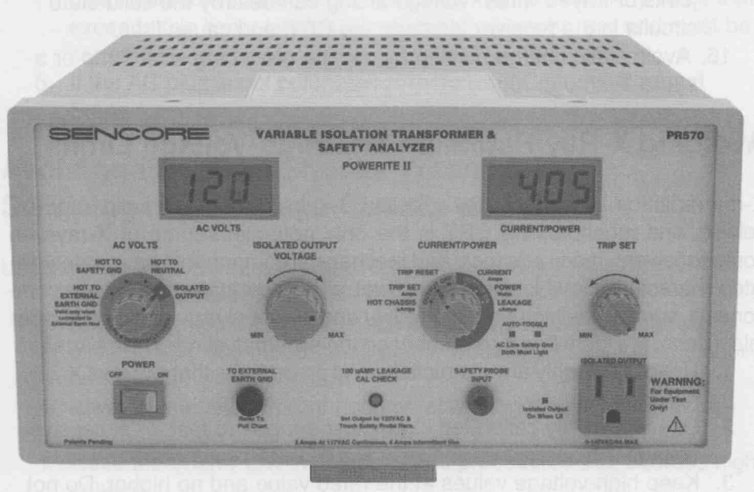
FIG. 3. A type of AC transformer
Avoiding Fire Hazards
Follow these rules when working on the television to reduce the chances of creating a fire hazard:
1. Do not let flammable materials come into contact with the CRT, power resistors or output transistors.
2. Prevent voltage arcing and static charge buildup.
3. When replacing a fuse or circuit breaker, use an external match as a replacement.
4. Never jump fuses with wire or other conducting material.
Working with a CRT
When working with a CRT, it is possible to receive a severe shock, a burn from extremely hot connection, or an injury from an implosion—a rapid in rush of air when the vacuum is broken. When an implosion occurs, shards of glass can cause injuries. Therefore, follow these guidelines when working with CRTs:
1. Before working with a CRT, slowly discharge the anode connection using a 10 megohm, 15W or greater resistor, and connecting it to a good ground. Do not short the anode connection to ground instead of discharging the anode connection.
2. Check the CRT carefully for broken seals, cracks, scratches or any other flaws in the surface.
3. Always wear safety glasses and gloves when handling a CRT, and do not handle a CRT when other people are nearby.
4. Safely dispose of defective CRTs. Some CRT manufacturers offer a recycling program for disposing of old or defective CRTs, many times at the manufacturer’s expense. For information, call the manufacturer of the CRT you are replacing and inquire whether they offer a CAT recycling program.
5. Always replace a CRT with one that is factory authorized for the model and brand of television for which the replacement is in tended.
6. Do not overtighten the mounting hardware.
7. Make sure the CRT and any connected parts are properly grounded.
Note: There are now laws on the disposal of CRTs due to high lead content in the glass. Be sure to dispose of CRTs in an approved manner.
FIG. 4. A degaussing coil.
8. For color televisions, make sure the degaussing coil (shown in FIG. 4) is not punctured or pinched. With the degaussing coil unplugged, check each lead using an ohmmeter. If the coil is good, the ohmmeter should read very low resistance.
General DATASHEET Safety Symbols
When you work with DATASHEET television schematics, be aware of the following symbols:
# : For safety, use only equivalent replacement part; see parts list.
* : Circuitry not used in some versions of this particular TV. Circuitry used in some versions of this particular TV.
+ : Ground.
Chassis ground.
Common tie point.
Taken from common tie point.
Schematic : Voltage source tie point.
A —: Cabling; heavy lines reduce the use of multiple lines.
General DATASHEET Safety Precautions
The following safety tips are commonly given in the DATASHEET to aid the repair technician and prevent safety problems:
Before replacing parts, disconnect power source to protect electrostatically sensitive parts. Do not attempt to modify any circuit unless so recommended by the manufacturer. When servicing the receiver, use an isolation transformer between the line cord and power receptacle.
Use extreme caution when servicing the high voltage circuits. To discharge static high voltage, connect a 10K ohms resistor in series with a test lead between the receiver and CRT anode lead. DO NOT lift the CRT by the neck. Always wear shatterproof goggles when handling the CRT to protect eyes in case of implosion.
Be aware of the instructions and procedures covering X-ray radiation. In solid-state receivers and monitors, the CRT is the only potential source of X rays. Keep an accurate high voltage meter available at all times. Check meter calibration periodically. Whenever servicing a receiver, check the high voltage at various brightness levels to be sure it is regulating properly. Keep high voltage at rated value, NO HIGHER. Excessive high voltage may cause X-ray radiation or failure of associated components. DO NOT depend on protection circuits to keep voltage at rated value. When troubleshooting a receiver with excessive high voltage, avoid close contact with the CRT DO NOT operate the receiver longer than necessary. To locate the cause of excessive high voltage, use a variable AC transformer to regulate voltage. In present receivers, many electrical and mechanical components have safety-related characteristics which are not detectable by visual inspection. Such components are identified by a # on both the schematic and the parts list. For SAFETY, use only equivalent replacement parts when replacing these components.
For cold leakage checks for receivers with isolated ground, unplug the AC cord, connect a jumper across the plug prongs, and turn the power switch on (if applicable). Use an ohmmeter to measure the resistance between the jumped AC plug and any exposed metal cabinet parts such an antenna screw heads, control shafts, or handle brackets. Exposed metal parts with a return path should measure between 1M-ohms and 5.2 ohms. Parts without a re turn path must measure infinity.
For a hot leakage current check, plug the AC cord directly into an AC outlet. DO NOT use an isolation transformer. Use a 1500 ohms, 10W resistor in parallel with a 0.15uF capacitor to connect between any exposed metal parts on the receiver and a good earth ground. Use an AC voltmeter with at least 5000 ohms per volt sensitivity to measure the voltage across the resistor. Check all exposed metal parts and measure voltage at each end. Voltage measurements should not exceed .75 VAC, 500pA. Any value exceeding this limit constitutes a potential shock hazard and must be corrected. If the AC plug is not polarized, reverse the AC plug and repeat exposed metal part voltage measurement at each point.
Perform a final SAFETY CHECK before returning receiver to customer. Check repaired area for poorly soldered connections, and check entire circuit board for solder splashes. Check inner board wiring for pinched wires or wires contacting any high wattage resistors. Check that all control knobs, shields, covers, grounds, and mounting hardware have been replaced. Be sure to replace all insulators and restore proper lead dress.
Quiz
1. Why is it important to discharge a CRT before working on it?
2. What are two sources of arcing?
3. What is the main source of X-ray radiation in a television?
4. What is an implosion?
Key
1. So that the technician will not be shocked.
2. Pointed solder joints or frayed wires.
3. Excessively high-voltage power supplies.
4. A rapid inrush of air when the vacuum in a CRT is broken.