The ‘DC 300B ’ originally appeared in the Danish magazine High-Fidelity ’ (No. 689, 1987). It is here rewritten by the author.
------------------
ABOUT THE AUTHOR
Mr. Mortensen lives in Denmark, is a full-time high school teacher with a Masters Degree in Danish and English, and has published some works of literary criticism (in Danish). He has been an active, amateur jazz musician, but during the last couple of years he has devoted most of his spare time to high fidelity design, contributing to the Danish magazine, Hi-Fi & Electronics.
---------------------
TUBES SEEM ABLE to give a more musical rendition of recorded music. However, we also know that any tube power amplifier is a compromise. Either you get a very good low-frequency performance and a rather dull high-range, or you get a good mid and high-range and a poor low-frequency performance. This is not due to the tubes as such, but the high impedance levels of the valves, which make an output transformer necessary.
Although modern transformer technology has come up with remarkable improvements, such devices are still wanting. One solution to the problem is, for example, Julius Futterman's output transformerless (OTL) circuits.
These are among the most fascinating pieces of audio circuitry I have en countered-and they do perform extremely well.
The OTLs do, however, have their own problems. For one, they are quite unhappy with low speaker impedances.
Those below 7- 8-Ohm are definitely not their cup of tea. They do drive the Magnepan MG IIb, and I've also heard some claim that they do a good job with some home-constructed ribbons, but nevertheless, they are still problematical--mainly because of the power consumption. A set of OTL3s will consume 1,000W idling, and at normal listening levels, around 1.5kW. Friends who are in possession of such gadgets say their electricity bill clearly shows how much music they have listened to.
The question is whether it is possible to get the musicality, the softness and transparency of tubes without sacrificing economy, a large number of the speakers on the market, and either of the extremes of the audio band. My original idea was to combine a high quality tube driver with a very fast MOSFET current amplifier. MOSFETs do operate somewhat like valves, any way. The 300B is my answer. It does sound very much like a tube gadget, it will drive low impedance speakers, yet it is also a MOSFET amplifier.
Topology
The basic topology of my DC300B is: an amplifying differential input stage, where the necessary frequency-corrections are made, followed by a voltage gain stage directly coupled to a low-impedance driver, which will drive a MOSFET current amplifier. I decided to employ AC-coupling to and from the dual cascode stage. I could have used DC-coupling between the tubes and the MOSFETs, but the circuit would be somewhat more complicated, requiring a servo-circuit. In spite of this, it would prove very difficult to achieve complete stability. Thus, I adhere to the view that a good capacitor is preferable to a simple servo-circuit.
My topology is not all that different from New York Audio Lab's Moscode idea (NYAL is now out of business- Ed.), but instead of the simple triode voltage amplification, I decided to use a cascode-voltage amplifier for reasons I will outline below.
--------Fig. 1
Feedback
In the old days of tube power amplification, designers strove to employ as much feedback as possible. Thus it was an impressive achievement when Julius Futterman proved that his OTL circuit could operate with 60dB feedback with out instability. Early transistor designers adhered to the same idea, and it became possible to reduce total harmonic distortion (THD) and increase the damping factor tremendously. Impressive figures appeared: THD below measuring equipment residual, damping factors of 400-600, and so forth.
Unfortunately, the sound of these de signs was horrid. Recently, designers are returning to moderate amounts of feedback, or no feedback at all.
I would not deny that feedback is in itself a good thing--but, like so many other things in this world, it should be handled carefully. Several designers prefer quite moderate amounts of feedback.
Jean Hiraga states that one of his problems during development of his ‘'Monster ’ was to get semiconductors with low enough He.? It goes without saying that Otala's findings were a major breakthrough in advanced audio design.
In terms of specifications, my aim was a closed-loop THD of 0.1% at full output - 1dB, and a damping factor of not less than 50 (into 8 ohm). Calculating backward, 30dB of feedback seemed sufficient.
The Differential Stage
I chose a well-known, and pleasant sounding pentode as my input valve. A pentode operates much like a transistor in terms of distortion-producing mainly odd-order harmonics. Yet in this con text, that is not as important. This front end only provides a gain of about 25dB (open-loop). Pentodes are also widely used in input stages; the OTLs from NYAL, the valve-based Citation, and Dynaco are a few examples. Only Radford seems to prefer a cascode.
Since the EF86 has a long tradition in audio technology, sounds pleasing, is relatively free of microphony, and is equipped with a bifilar filament and internal screening, I found it a bargain.
To limit gain and to reduce low-frequency phase shift I decided to operate the EF86 as a triode, with the screen grid connected to the anode.
This stage's open-loop bandwidth is not large. Its -3dB point lies some where around 25kHz (without R5 and C2). Yet, to ensure stability, we must reduce gain at high frequencies quite drastically. The R5 and C2 network in conjunction with the plate load takes care of this. The time constant, 7, of this filter should be around 1-usec (only R5 and C2). Other component values at this spot may change the sound of the amplifier. 270pF and 3.8 k-O will give about the same 7, but the rolloff becomes less steep. These alternative component values give a marginally poorer stability performance.
To reduce the risk of TIM I have included the traditional input filtering network, R2 and C1.
Feedback from the output is applied to the cathode of V1 via resistor R13.
The circuit board will accommodate a traditional phase-shift compensation network, but because of the carefully tailored filtering in this stage, that has proven unnecessary.
The overall closed-loop gain of the amplifier is 27dB (21x), which means that about 1.6V RMS will develop 34.7V RMS across the output terminals (150W, 8 ohm). This gain is slightly lower than that of ordinary European standards, but in accordance with many American makes of preamplifiers. It should not cause problems.
The input stage needs only 120V. On the circuit board I provide space for four zeners, connected in series (three 33V and one 20V/1W), which give a very stable voltage supply, but they do add some noise (approximately 2dB) despite the decoupling. I decided to live with the extra noise because the stable voltage results in a far more relaxed sound and a much better handling of transients, than does an ordinary dropping resistor decoupled with a large filter capacitor.
The preamplified and preconditioned signal is then fed to the dual cascode stage via C4. This capacitor is very critical; only the best quality will do.
In my prototype I used a 0.1 uF/630V, MKPI10 from Wima. Of course, 630V is far higher than needed here, but many believe high-voltage capacitors generally sound much better than low voltage types. Of course, a more modest component at this spot will isolate the grid of V2 from the plate voltage of V1 and let the signal pass.
The Dual Cascode
This stage is a high quality, high gain voltage amplifier with very low output impedance. It consists of a cascode volt age amplifier (V2) and a low-Z output stage whose gain is slightly less than unity.
The voltage amplifier must provide the full voltage swing needed to develop the required output power. 150W into 80 will demand 34.7V RMS. If we limit our choice of tubes to readily available smallish types, only two will suffice: 6D]J8 (and equivalents) and 12AU7. To my ears 6DJ8 is undesirable; most makes have far too dry a midrange and a somewhat harsh or strident top end.
Fortunately, the 12AU7 sounds very nice. Since our aim is limited open-loop gain, the quite low mu (17) of the 12AU7 serves very handily.
Cascodes in audio circuitry are still subject to debate among audiophiles, but the advantages of the cascode can not be ignored. It provides high gain and low distortion, and the distortion it does produce is almost exclusively second harmonic. Their linearity is also good because of the inherent feedback.
Nelson Pass (among others) has pointed out the most striking feature: a cascode will give a far better sense of dynamics than any other amplification device? V2 has a gain of about 30 (approximately 29dB). Without feedback it will deliver close to 60V RMS with less that 2% (mainly second-harmonic) distortion. At normal listening levels, the distortion will be in the region of 0.5-1%, still without feedback.
Coupled Cathode
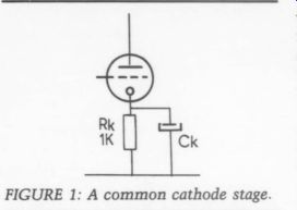
In this case I decided to avoid decoupling of the cathode resistor, thus introducing some local feedback. My reason is twofold. First, we want to keep open-loop gain at a reasonable level. Second, recent experiments with preamplifier circuitry have convinced me the ‘'muddy ’ bass often associated with tubes is caused by problematic cathode decoupling, which is not surprising at all, but somehow not fully appreciated in practical engineering.
For example, Fig. 1 shows a common cathode stage with a 1k-ohm cathode resistor and decoupling. A typically large value of Ck could well be 220uF. At 40Hz this will have a Z of about 18 ohm (disregarding losses). Assuming a constant current of 2mA this Z will develop about 36uV. Since the cathode is the noninverting input of the amplification stage, this kind of unwanted signal is added to the signal at the grid, and appears, in some form or other, amplified at the anode. 36pV may not sound too bad, but try calculating the value at 20Hz-not to mention subsonic 'noise' peaks. Moreover, don't forget that these unwanted signals are not just 180° out of phase with the input--they are completely out of phase with any thing. Clearly these spurious signals are also likely to reach far up into the mid range. To make things even more interesting, the assumption of a constant 2mA cannot hold either.
If we imagine that large capacitors are not leaky at all, a good quality 10,000uF cap, in parallel with a good film type will be sufficient; or, no de coupling at all, which is by far the best-if we can do without the extra gain. The cascode voltage amplifier is DC-coupled to the White cascode stage.
The most striking feature of this cascode is its very low Z_out -- just what we need to drive MOSFETs properly.
Current Hogs
The problem with MOSFETs is that even though they are high-impedance devices, they do require some current to charge and discharge the coupling capacitor between gate and substrate/ source, C_iss, on the chip. The value of this capacitor is 100pF at about 1A I_ds, and a maximum 600pF above this level (SK135). The complementary J50 has a max capacitance of 900pF. To match them we add 330pF externally to the SK135, thus getting about 1,800pF in each side.
The rise time of the Hitachi MOS-FETs is about 0.2usec at maximum I_ds (about 0.1 usec at around 100mA I_ds). To use their full potential, we should introduce no more that 100 ohm series resistance and a constant, unlimited current source. An arrangement of this kind would give a bandwidth of about 1IMHz, but, contrary to what some might expect, this is not a good idea, because keeping parasitic oscillations under control in rather simple audio amplifiers is very difficult.
But how low a drive-Z do we actually need? A bandwidth of 20kHz requires a rise time of about 50usec, thus about 25 k-O should do. Unfortunately, this would give us a very slow, and probably horridly sounding amplifier. Listening tests and various experiments have convinced me that a too low drive-Z can produce a quite transistor-like treble, whereas a too high Z will give a dark, lifeless sound. Some designers use as much as 2.5 k-O source impedance; I have chosen 155 ohm-plus a 680-ohm gate stopper.
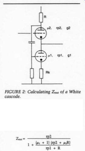
FIGURE 2: Calculating Zout of a White cascode.
Cascode Calc
Fellow experimenters might be interested in calculating the Zou (ohms) of a White cascode (see Fig. 2):
Zoun --- 22 1% (m1 + 1) (rp2 + paR) pl + R
where,
p = amplification factor
rp = plate resistance of the tube
g = transconductance in A/V
By adding a cathode resistor, Rk, the plate resistance will be increased by a factor (1 + gRk), thus giving: (see eqn above)
-- p2 (1+ g x Rk) 1 4 + DI(p2 x (1 + gRK)) + uR] pl + R
To keep the impedance low and to pro long tube life, I decided to use two 12AU7s in parallel. Such a device has the following specifications:
up = 17, rp = 3,850ohm, g = 4.4mA/V.
For my DC300B this gives, as mentioned, 155 ohm. If you wish to experiment with this very critical point, just increase the plate resistor of V3 (R15). Of course, this will require some readjustments of the preceding cascode. I assume that if you embark upon such ad ventures, you know what you are doing, but some words of caution; the DC-potential at Tp4 must remain constant no matter what voltage swing the stage delivers.
Current Amp: Output Stage
The output stage of the DC300B is a fairly conventional source follower. I use two FETs in each side to increase the amplifier's current capacity. I considered using three, but we should be careful here because of the increased capacitive load presented to the driver stage. The voltage gain of this stage is slightly below unity.
In this discussion I shall not go into this stage's function since it has already been discussed in earlier issues of this magazine. I will, however, deal with some problematical points.
In this stage, a passive bias circuit is necessitated by using AC-coupling between the tube driver and the FETs. My solution is slightly different from the Moscode design, but the result is the same. Components R19, 20, 23 and 24 form two identical adjustable voltage dividers. These control both bias and DC on the output. For adjustments, please see the accompanying sidebar.
---------------------
PARTS LIST--TUBE CIRCUIT
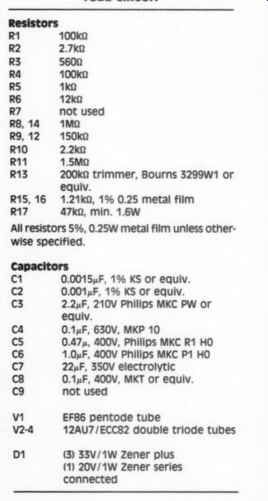
Resistors R1 100 k-O R2 2.7k0 R3 5600 R4 100 k-O RS 1 k-O R6 12 k-O R7 not used RS, 14 1 M-ohm R9, 12 150 k-O R10 2.2ka R11 1.5 M-ohm
R13 200 k-O trimmer, Bourns 3299wW1 or equiv.
R15, 16 1.21 k-O, 1% 0.25 metal film R17 47 k-O, min. 1.6W
All resistors 5%, 0.25W metal film unless otherwise specified.
Capacitors
C1 0.00154F, 1% KS or equiv.
C2 0.001.F, 1% KS or equiv.
C3 2.2uF, 210V
Philips MKC PW or equiv.
ca 0.1uF, 630V, MKP 10
C5 0.47, 400V, Philips MKC R1 HO
C6 1.0uF, 400V Philips MKC P1 HO
C7 22uF, 350V electrolytic
C8 0.1uF, 400V, MKT or equiv.
C9 not used v1
EF86 pentode tube v2-4
12AU7/ECC82 double triode tubes
D1 (3) 33V/1W Zener plus (1) 20V/1W
Zener series connected
-------------------------------
Bias is fed to the gates via R21 and 22. These resistors act like grid-stoppers--reducing the risk of parasitic oscillation--and they prevent naughty signals from the simple power supply from reaching the gates. The prime objective in this part is to safeguard the amplifier against instability. You should never forget that the gate of a MOSFET is sensitive, and even very small signals in a source follower stage of this kind can produce a destructive amount of power across the output terminals.
Capacitors C14 and 15 improve the dynamic stability of the bias. Detecting any change of behavior is impossible under ordinary listening conditions if they are omitted, but as soon as the level approaches the upper limit, these capacitors will store just enough current to maintain bias on the output devices during peaks where clipping due to loss of bias would otherwise occur.
As you can see, I omitted thermal feedback. It is not necessary, provided the FET' are run at about 100mA each.
At this level of bias they are very close to thermal stability, but this is also influenced by the passive bias circuit.
The trimmers must be high quality; conductive plastic or cermet will do, but ordinary carbon trimmers must be avoided.
Cap Choices
From the outset, I desired to rid the circuit of bipolar transistors, thus I have not experimented with replacing the passive bias network by active voltage generators. Such devices might enhance the dynamic stability of the bias, although I think the simplicity of this passive setup is a nice feature.
In this context it is worth noting that the output stage will work with a wide variety of power supplies. Using a 2x 33V (AC) transformer, the amplifier will give 70W (into 8 ohm); in this case, R24, R23 should be reduced to 10 k-O. A 2x 24V AC transformer will yield 35W ( 8-O); this sort of power will require R23 and 24 to be about 8.2 k-O. Likewise, if you increase to 2x 55V (AC), the device will produce just above 250W (8-Ohm); in this case, choose 18k ohm. (I have not tried the latter combination.) Coupling between the tubes and the FETs is accomplished by means of C10 and 11. In the prototype I used a 0.1uF/630V Wima MKP 10. These capacitors must be of premium quality.
Of course a 400V type will do, but high voltage types are generally better sonically. And the isolation between the 177V at Tp4 and the gates must be very good. If the worst happens and V4 breaks down, you might get close to 350V at Tp4. ‘Murphy ’ rules the world, you know.
Larger capacitors here will lower the low -3dB point of the amplifier, but you should be careful, because the DC stability or, to be precise, the DC recovery time constant of the entire circuit should be as high as possible.
Again, we're facing a compromise. The Moscode 300 displays some very odd behavior in the subsonic register which likely accounts for the massive bass reproduction of this device? Yet, with a bit of luck you just might strike the combination which gives exactly the bass performance you want.
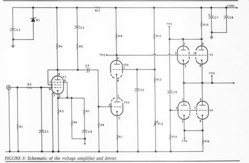
Fig. 3
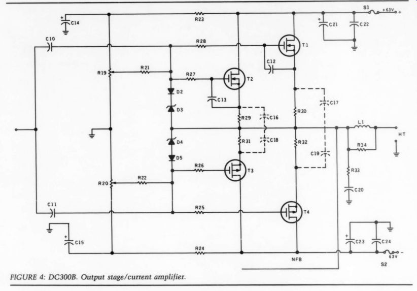
FIGURE 4: DC300B. Output stage/current amplifier.
Choke Overshoot
-------------- PARTS LIST: OUTPUT STAGE
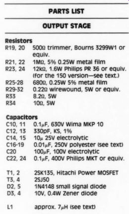
Resistors
R19, 20 5000 trimmer, Bourns 3299wW1 or equiv.
1 M-ohm, 5% 0.25W metal film 12k, 1.6W Philips PR 36 or equiv.
(for the 150 version-see text.) R25-28 680%, 0.25W 5% metal film R29-32 0.220 wirewound, SW or equiv.
R33 8.29, SW R34 100, SW R21, 22 R23, 24
Capacitors
C10, 11 0.14F, 630V Wima MKP 10 C12, 13 330pF, KS, 1% C14, 15 10x 25V electrolytic C1619 0.01xF, 250V polyester (see text) C20 100xF, 100V electrolytic C22,24 0.14F, 400V Philips MKT or equiv.
2 73,4 D2, 5 D3, 4 2SK135, Hitachi Power MOSFET 25J50 1N4148 small signal diode 10V, 0.4W Zener diode L1 approx. 7uH (see text)
Insulation for the power semiconductors (T03 house), screws, nylon screws, etc., aluminum angle (see text), S1 and S2 3.15 slow blow fuse.
-------------------------
Despite their various drawbacks, I decided to include source resistors (0.220). It is perfectly possible to do without them provided you use carefully selected MOSFETs. But that'll soon prove an expensive experiment, be cause you must buy several times more than you need.
The source resistors help balance the amount of current drawn by each of the two MOSFETs in parallel. These resistors also facilitate easy bias adjustment.
On the negative side, they increase the open-loop output impedance, which may lead to increased distortion and a lower damping factor. Despite these drawbacks, I recommend including them.
The inductance in series with the output reduces THD at high frequencies because it works as a low-pass filter, and it minimizes the risk of parasitic oscillation when cables and speakers are connected to the amplifier; but it also causes some ‘ringing’ on a square wave into reactive loads. I have noticed a lot of fuss about ringing and overshoot-performance into reactive loads recently. Quite frankly, I think this parameter is relatively un-important. A fairly large number of high-end amplifier show decidedly horrid behavior under these circumstances, and nevertheless, sound nice, Moreover, the reduction of overshoot and ringing is exclusively a matter of matching the coil with the damping resistor.
Poor Chips
I do respect oscillation, though, and the 1uF/ 8-O square-wave test is a good indicator of instability. The DC300B has a quite conventional performance in terms of overshoot into reactive loads, and it is stable in 1uF/ 8-O reactive loads, up to approximately 85V peak-to-peak (PP). The coil should have an inductance of 7uH. You can make this from 0.8mm copper wire, two layers of 20 turns each, on a 10mm, nonmetal coil former.
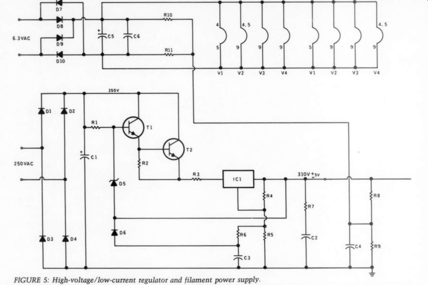
FIGURE 5: High-voltage/low-current regulator and filament power supply.
In connection with this amp, you may have to deal with one likely problem: some FETs tend to oscillate at particular voltage levels and at particular points on the sine wave. This oscillation is caused by stray reactances on the circuit board, on the chip, in wires and so forth. A signal generator, an oscilloscope and a heavy duty dummy load will easily detect it. I suggest you use a 10kHz sine wave, starting with zero level on the input of the amp and increasing the level until the amplifier clips. Any misbehavior will be obvious.
By touching the case of the suspected MOSFET you should be able to make this oscillation disappear. When you have found the culprit, solder a capacitor, 0.01uF/250V polyester (or better), across the relevant source resistor.
If you lack an oscilloscope your ears will do. This sort of problem will make the amplifier sound extremely strident, distorted and horrible. Again, if you touch the MOSFET with a finger (keep the other hand in your pocket) the sound quality will improve. To avoid the inconvenience of keeping a finger on the MOSFET, I suggest you add the capacitor. Since only one MOSFET is apt to be at fault, instead of patching it up with capacitors you should consider replacing it. Interestingly, this sort of oscillation does not change the amplifier's THD factor at other voltage levels. Of approximately 35 MOSFETs I've used, only one showed this kind of misbehavior.
This concludes Part I of the DC300B amp. In Part II the author outlines the power supply, and details the construction and set-up adjustments to complete the project.
REFERENCES
1. Futterman, J., ‘An Output Transformerless Power Amplifier, ’ JAES, Vol. 2, No. 4, October 1954.
2. Hiraga, Jean, ‘Monstret er paa trappeme, ’ High Fidelity ( Copenhagen), Nos. 6-8, 1987.
3. Hamm, Russel O., ‘Tubes versus Tran sistors, ’' JAES, Vol. 21, No. 4, May 1973.
4. Pass, Nelson, 'The Cascode, ’ Audio, No. 6, 1978.
5. Michaelsen, Madsen og Moller, ‘Meterlig Hybrid. Review of the Moscode 300, ’ High Fidelity ( Copenhagen), July, August 1985.
6. Otala, et al., ‘L'llm ou la distortion dans l'interface amplifacateur-enceinte acoustique. In selections from L'Audiophile, 1985.
7. Hood, ].L. Linsley, 'A 80-100 Watt Audio Amplifier, ’ Wireless World, June, July, August 1982.
--------------
PARTS LIST--High voltage / low current reg. and pwr supply.
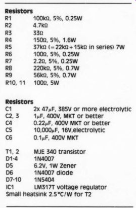
Resistors
R1 100k, 5%, 0.25W R2 4.7 k-O R3 330 R4 1509, 5%, 1.6W RS 37k (=22 k-O + 15k in series) 7W R6 1009, 5%, 0.25W R7 2.29, 5%, 0.25W R8 220k, 5%, 0.7W R9 56 k-O, 5%, 0.7W R10, 11 1009, 5W
Caps
C1 2x 474F, 385V or more electrolytic C2, 3 1uF, 400V, MKT or better ca 0.22uF, 400V MKT or better cs 10,000xF, 16V, electrolytic C6 0.1xF, 400V MKT
Etc.
T1, T2 MJE 340 transistor
D1-4 1N4007 D5 6.2V, 1W Zener
D6 1N4007 diode
D7-10 1N5404
IC1 LM317T voltage regulator
Small heatsink 2.5°C/W for T2
-------------------
Also see:
DIRECT MODS FOR THE MAGNAVOX CDB-560 By Kenneth Beers
Issues of Reliability and Validity in Subjective Audio Equipment Criticism, by Lawrence L. Greenhill, M.D. Scientific techniques which might improve listening tests
Direct Cut Myths and Problems, by Adrian Hope--A visit to Teldec, examining prospects for the D-to-D phenomenon.