APPLE II STEREO REMOTE CONTROL
The SMALL FOUR-PIN jack labeled ‘remote’ on the back of my amplifier started me thinking about adding remote control to my stereo. When I looked further into the jack's purpose, I found that it plugged into a specific Sony remote control component, which would enable its owner to control all his Sony components-integrated amplifier, cassette deck, turn table, and CD player-with a single remote control. It also could turn the whole system on or off at a set time, serving as a master controller.
Of course, if you buy any other brand, say a Technics CD player, as I had, this wonderful component won't work with your system. I like the concept though, and thought it would be very useful if I could make a similar controller which would work with all of my components.
I decided to use as my controller an Apple 1+ computer, which had sat un used in our basement for a while. Obviously you can't just plug the computer into your CD player; links must be made between all components and the computer. Every link needs to translate the computer's commands into a command receivable by the component. The link might also have to perform as a translator, decoding the component's outputs and sending them to the computer.
------------------
ABOUT THE AUTHOR
Peter Khoury graduated from the North Carolina School of Science and Mathematics, has completed two years at Cornell's Applied and Engineering Physics Department, and is currently taking a year at Cambridge, England. His first interest in electronics was stimulated by a Heathkit individual learning program on digital electronics.
----------------------
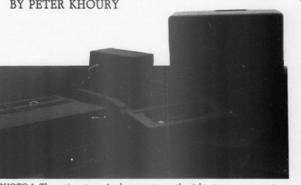
PHOTO 1: The entire set-up. Apple computer on the right, stereo components on the left.
---------------------
I started by working on a link be tween the Apple and my CD player, with two specific functions. I wanted the computer to be able to simulate key presses of any key on the front of the CD player. I could then start, pause, search, or even program my CD player, through the computer.
I also wanted the Apple to be able to tell which CD was currently in the machine. To implement this part of the link, the player could conceivably read the unique ID code, which is on the outer tracks of every disc, and send it to the computer. After opening the CD player and looking inside, I decided against this approach for two reasons.
It would involve modifications to the CD motherboard, a tedious and difficult process, and I did not have detailed enough information about the player to know specifically what modifications to make.
An easier way, I decided, would be to enable the link to read the display.
This method didn't even require modifications to the daughter-board which contained the keypad and display. The link simply must access the connecting wires between the two, so the Apple could read the initial display which occurs when a CD is first put in the player, before the play button has been pressed. This information, which shows both the number of tracks and the total time on the disc, doesn't necessarily have to be unique but has been for the approximately 150 discs I have checked. By reading this information, the computer can positively identify any of my discs. This accomplishes the second purpose of the link.
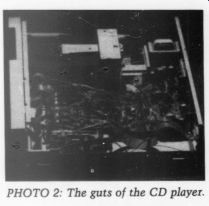
PHOTO 2: The guts of the CD player.
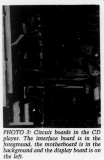
PHOTO 3: Circuit boards in the CD player. The interface board
is in the foreground, the motherboard is in the background and the display
board is on the left.
The first step in making this link was getting technical information about both machines I wanted to connect. For the Apple, I already had the Technical Reference Manual which contained all the information I needed. For the Technics, however, I bought a set of schematics and technical descriptions normally used by repair shops. This documentation cost only $10. Because the intended use of the information was for repair shops, it did not thoroughly describe the circuitry. Instead, much of it was devoted to problem symptoms and solutions. It is nice to have around if you ever want to do your own repair work. I gleaned enough information from it, though, to come up with a workable design for the link.
Before I describe the link design, you need to know how the keyboard and display of the Technics SL-P1 CD player work. Each key on the CD player is placed at the junction of a row and column of wires and it can make a connection between that row and column.
There are 9 columns, 4 rows, and only 21 keys, so not all junctions are occupied. To determine whether a key has been pressed, a chip on the motherboard raises each of the ten columns to 5V, one at a time. As it raises each column high, it tests all four rows for a high level. If a key on the column has been pressed, the corresponding row will be high and the CD player will register that key. The player will not register a key if no rows are high, or if two keys are pressed at once.
To make the link simulate a key press, the appropriate row for the key desired must be raised high by the computer, when the proper column corresponding to the key is high.
The display is multiplexed, in other words, it displays each of the digits one at a time, but cycles them so fast that the eye just sees a solid display. To turn the digits on one at a time it makes use of the same column wires used by the keypad. Besides relating to a group of keys, a column also corresponds to a digit on the display of the CD player.
Since eight digits are displayed, some columns are unused. There are another eight wires, output by the mother board, each of which matches with one of their eight different segments in all of the different digits. When one of these lines goes low only one segment lights up, the one in the digit specified by the column that is currently high. If two of the eight segment lines are low, then two segments in that digit will light up.
When the chip on the motherboard raises a column high, it has two tasks; to check if any of the four rows is high, and to send to the display the eight lines of segment information of the digit selected by the column. To tell what is being displayed on a particular digit, all we need to know is the status of the eight segment wires when the column for that digit is raised.
The link between the two machines consists of two circuit boards, one in each, and a 17-wire cable running be tween them. I'll start by describing the setup that went inside my Technics CD player. The housing conveniently has a space approximately two inches wide beside the motherboard-perfect to place another board. Also, the four 8-wire cables from the display board simply clip into connectors on the motherboard and it is very easy to add another set of connections to tap into these. Unfortunately, but not surprisingly, the player does not have any holes on the back to place a connector.
I had to make a hole in which to mount my DB-25 wire connector. Despite the fact that I only used 17 of the 25 connections, I chose the DB-25 because it is inexpensive and easy to obtain.
Those of you with punches specially made to create those holes will be able to skip the agonizing time I spent with a drill and nibbler, and you will also get a neater result.
Unfortunately, the CD player's power supply is a little inadequate; it can't handle the strain of nine additional low-power Schottky (LS) chips. To remedy this I had to put another hole and jack in the back of my player for a power supply.
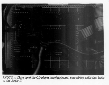
PHOTO 4
The major functional component of the board in the CD player is a comparator and decimal-to-binary coded decimal (BCD) encoder chip. This combination singles out the particular column of interest, either to press a key or read a digit. Each of the nine columns switches between -30V and 5V.
The combination of a diode and pull down resistor tied to ground, can be used to convert these voltage levels to transistor-transistor logic (TTL) ones,
0-5V. Ideally, each of these lines would Continued from page 8 be sent directly to the decimal-to-BCD encoder. However, the 74LS147 en coder chip I used inverts all of the in puts and outputs; they are all active when low. To correct this, each of the input lines are inverted with 74LS04 chips and then fed into a decimal-to BCD encoder. The output of these connections are the four BCD lines which cycle through a series of inverted BCD numbers, as each of the columns goes high, one at a time.
These four lines are connected to one side of a 4-bit comparator, 74LS85. The other four inputs to the comparator come from the computer. When the output of the encoder matches the in put of the computer, the equal line on the comparator goes from low to high.
This line provides a signal which indicates when the column selected by the four computer lines has gone high.
If the inputs on the computer lines change the column's selected line will go high at a different time, when a different column goes high. This column's selected line can be used for both pressing a key and reading the display.
To enable the board in the CD player to simulate a key-press, the column selected line is split four ways and each is attached to one input on a two-input AND gate. The other inputs for all four gates come from the computer, and each corresponds to one of the rows on the CD keyboard. When the column the computer selected goes high, so does the A = B or equal line of the comparator. Now one of the inputs to all four AND gates is high, and they will act to pass the values of the four inputs from the computer through to the out puts, which are connected to the row inputs. When the column on the CD player changes, the comparator output goes low again and the AND gates' out put does the same. By connecting this output to a row in the CD player, the player cannot distinguish the signal from a normal key-press and registers it as such. Of course, if the computer had two rows high at once, it would be like someone pressing two keys at once, which the CD player ignores.
If this signal is directly attached to the CD player, the outputs of the AND gates would normally be low unless the computer was pressing a button, and these low outputs would always be pulling the row down to ground, even if a key was pressed. Consequently, the CD player could not register a keypress on its front panel. This would not do because you still want to be able to operate your CD player manually. To alleviate the problem I put a diode in the line so that it would only pull the CD player's rows high, but not low.
Now, by using eight input lines you can use the keys on the player.
The other purpose for the equal line output from the comparator is to latch data about the digit corresponding to the column. Ideally, the output would
----------------
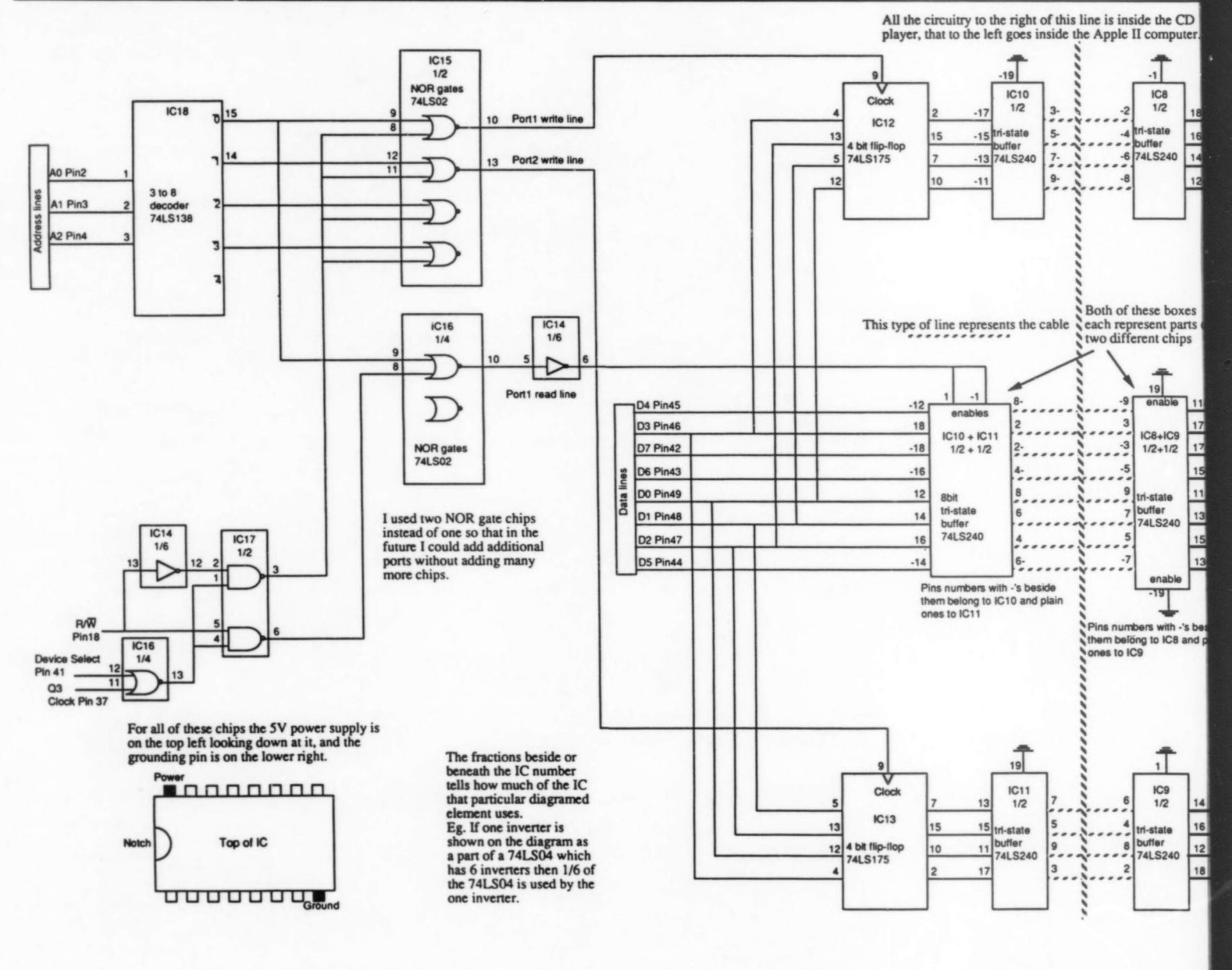
FIGURE 1: Schematic-all the circuitry to the right of the dashed line is inside the CD player, that to the left goes inside the Apple II. CN401-404 represent the four connectors on the motherboard where the cables to the display board are attached.
The set of lines running to the right are the CD's cables that go to the display board, and the lines off to the left are wires you attach to the connector. Of course, a third set of wires goes to the motherboard (not shown). The labeling on the connectors corresponds to the labeling on the motherboard. ---- All the circuitry to the right of this line is inside the CD player, that to the left goes inside the Apple II computer.
For all of these chips the SV power supply is on the top left looking down at it, and the grounding pin is on the lower right.
I used two NOR gate chips instead of one so that in the future I could add additional ports without adding many more chips.
The fractions beside or beneath the IC number tells how much of the IC that particular diagramed clement uses. Eg. If one inverter is shown on the diagram as a part of a 74LS04 which has 6 inverters then 1/6 of the 74LS04 is used by the one inverter.
Both of these boxes each represent parts two different chips
This type of line represents the cable
Pins numbers with -'s beside them belong to IC10 and plain ones 10 IC11
------------------
------------------
PARTS LIST
CD Player's Board Resistors R1-R17 R18 Diodes D1-21 ICs
2 741504 inverters IC3 7415147 BCD encoder Ica 741.508 Quad two-input AND gate IC5 7415373 8-bit latch IC6 7415123 one shot IC7 741585 4-bit comparator IC8, 9 7415240 8-bit Tristate buffers
3.3k ohm - 4.7k-Ohm silicon diodes
Miscellaneous
Six feet multicolored ribbon cable, DB-25 male connector, DB-25 female connector, 1-16-inch male jack, 1/16 inch female socket, 5V power supply, 2 x 3-foot circuit board with solder pads.
Apple II's Board ICs IC10, 11 8-bit Tristate buffer 74.5240 IC12, 13 Quad D flip/flop 74LS175 IC14 inverter 74LS04 IC15, 16 Quad two-input NOR gates 74LS02 IC17 Quad two-input NAND gates 74.500 IC18 3-to-8 decoder 74L5138
Miscellaneous
20-pin IDC connector socket, 20-pin IDC connector header, wirewrap prototype card with connection pins for Apple Il (50-pin PC card edge connectors on .10-inch centers.
-----------------------
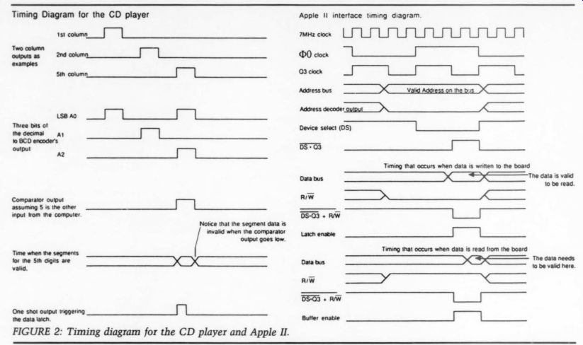
FIGURE 2: Timing diagram for the CD player and Apple II. Timing Diagram for the CD player. Apple Il interface timing diagram just trigger an 8-bit latch, like the 7418373, each bit of which would be connected to one of the seven segments on the display. The Apple could then read this information at its leisure.
Although this is the gist of what goes on, you must add some components to the circuit. Again, critical items are diodes and pull-down resistors which tame the -30V to + 5V inputs of the segment lines to more manageable 0-5V levels.
When I first used this scheme, wired, connected the board, and looked at the output, it was producing garbage which didn't accurately represent the digit.
After debugging the circuit, I found another problem: synchronizing the timing between when the data is avail able and when it should be latched.
Because the latch stores data any time the enable line is high, and since the column line stays high until (just a little) after information has finished being sent to the display, invalid information is stored on the chip. The solution is to put a one-shot in the line, whose duration is about half of a typical equal signal. I used a 74LS123 with a 4.7kohm resistor and 0.1uF capacitor. The one shot, though, triggers on a high-to-low transition, so an inverter must be placed before it. Once these changes have been made, the circuit works as 12 The Audio Amateur 1/89 advertised, providing the computer with information about any of the digits it desires.
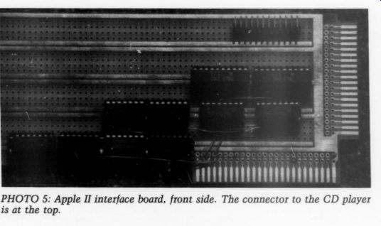
------------ Photo 5
The CD player's board is not quite finished yet. I added two buffering chips, 74LS240, which just provide strength to the signal in case I want to run the cable long distances. Another minor point is the power for the board.
As I mentioned before, I had to run a 5V power supply cable in the back of the player. To eliminate the need for this, I have thought of replacing the LS chips I used (which draw a fair amount of power) with compatible CMOS chips. Whether this will reduce the power demands enough, I do not know.
Now the Apple computer needs a way to send and receive the information. It must provide two sets of four outgoing lines; one for the input to the comparator, and the other for input to the four rows, as well as receive eight input lines coming from the segments of the display. You could conceivably build an adaptor to receive and send data between the CD player and a standard interface, such as the RS232 serial port or the IEEE-488 parallel port. This would provide the advantage of a standard interface but it would add complexity, especially if you wanted to add additional ports for input and output to other devices. Instead I chose to make an addressable card to fit in one of the slots of the Apple computer, which I could easily expand if I wanted any more ports. I designed the card so that each output port corresponds to a different computer address and each input also corresponds to a different address.
However, an input and output port can have thc same addresses. As an example, the card I designed, if placed in slot 3, has I/0 addresses of $COBO, through $COBF. If I store $06 to address $COBO, the lower four bits, 0110 binary ($6), will be latched onto the four output lines going to the comparator. Yet if I read address $COBO, it retrieves the byte of data from the segments of the digit selected on the CD player.
I'll describe the pinout of the Apple II slot, so you can understand the design of the board. This is not a complete description, but it mentions the vital pins; see the Technical Reference Manual for more detail.
Device select (pin 41) is active low and becomes active when the 16 bytes of I/O memory corresponding to the slot are addressed.
Address lines 0, 1, 2 (pins 2, 3, 4) indicate the lower three bits of the address to which the data was written or read by the computer.
Line R/W (pin 18) is high when the address given by the address lines is being read from, and low when it is being written to.
Q3 (pin 37) is a clock signal that is used to tell when data is valid. When it is low, valid data is on the data bus available for reading by the board. Also, any data written to the board should be placed on the bus during this time.
Data lines 0-7 (pins 42-49) either output the data being written or receive the data being read.
Because both the device select line and the Q3 clock are active low, I NORed them together. The output of this combination now goes high when ever the board is being addressed and valid data needs to be read or written.
To tell which action (reading or writing data) is occurring, you can use the in put from the R/W line.
I took this new select line and fed it into one input of a NAND gate, the other input coming from the R/W line.
The output of this gate then goes low when one of the addresses assigned to
--------------------
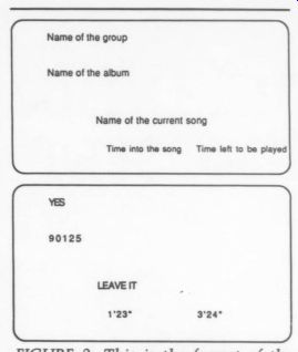
Name of the group; Name of the album; Name of the current song; Time into the song; Time left to be played
FIGURE 3: This is the format of the computer screen. A disc by the group Yes, 90125, has been placed in the CD player, and has been programmed to play the song ‘Leave It, ’’ which is 4 min., 47 secs. long.
----------------------
the card is being read and when data needs to be placed on the line. Call this line Read Valid. I connected another NAND gate similarly, except as a second input it uses the inverted R/W line.
This combination goes low when one of the addresses assigned to the card is being written and the data being writ ten is valid. Call this one Write Valid.
If we could decode the address being accessed, it could be used to select the proper port to read from or write to.
The 74LS138 does exactly that. It is a 3-to-8 decoder which partially decodes the address which the Apple accesses.
It receives a binary number on three lines and, depending on what number is input, it activates one of eight different output lines. Like the Read Valid and Write Valid lines, the outputs of this chip also go low when active.
Take two lines, one from any of the eight wires out of the decoder and another from either the Read Valid or Write Valid lines and, when combined properly, they will indicate when the proper conditions exist for a unique port to be accessed. Sixteen combinations each correspond to reading or writing one of eight different ports. For Port 2 to be written to, it must be ad dressed, which is indicated by the second output line of the decoder going low, and at the same time, the write has to be valid, as indicated by the Write Valid line going low. Joining these two signals together with a NOR gate will produce an output line which goes high when both of these conditions exist and which can activate the chips to implement either a read or write function. The chips I activated in a particular port consisted of either latches or buffers. A latch would be triggered if the computer wrote data to an address so that the information could be stored and continuously be available for the CD player to receive. If the computer reads an address, a buffer would need to be triggered so that the information could be placed on the data bus for use by the computer.
The latches I used, 74LS175s, are actually quad D flip/flops. Two of these with the lower four data lines connected to each made two output ports.
One was dedicated as the column in put to the CD player, the other as the row input and each accessed with a different computer address. These flip/ flops latch data on a change from low to high of their clock input. This can just be fed in from one of the NOR gates.
I choose to put the port controlling the columns at address $COBO by triggering the latch from a NOR gate whose two inputs are the Write Valid line and the 0 output of the 3-to-8 decoder. Similarly, I put the row port at address $COB1 by connecting the NOR gate to the Write Valid and the 1 output.
For the input buffers I used a pair of 74LS240s. Another NOR gate triggered these buffers, letting the data from the digits of the CD player pass to the computer. I placed the input port at address $COBO by connecting the NOR gate to the Read Valid and the 0 output of the decoder.
The addresses given are particular for a board in slot 3. As a board moves from slot to slot, the addresses of the ports stay the same relative to one another but their absolute addresses change. If the board moved to slot 4 the addresses of the two write ports and the read port would be $COBO, $COC1, and $ COCO respectively.
I mentioned that I used two 7415240s as input buffers. But this ac counts for only 8 out of the 16 buffers provided on the two chips. The other eight became output drivers, just as in the CD player, so that the information could be sent over a long cable if necessary.
Now that the whole link has been forged and the computer can communicate with the CD player, the computer needs to be programmed to operate it properly. At the start I wanted the computer to be able to do a number of basic things. Given a disc, I wanted in formation to be displayed on the screen about the disc, my favorite tracks to be programmed and played, and also information about the track playing. I decided to do most of the programming in Apple's BASIC almost by default.
The language is straightforward, easy to program and already on the Apple. Un fortunately, BASIC is not fast enough to display some of the information I wanted, like time elapsed into a song and time remaining to be played in a song. For this feature I turned to assembly language.
The programs I used are available.
[For a computer printout of the listings, write to Audio Amateur and enclose a self-addressed, 9x12 envelope with 65¢ postage.-Ed.]
They should be commented thoroughly enough so that you can understand them without any added description. Unless you follow my wiring diagram precisely, the row and column numbers for a particular key will be different, as well as the numbers that stand for the different digits. Consequently, you will have to change some of the data in both pro grams.
BASIC is an inherently messy language and my programs are still rough around the edges. I just used a sequential search to look for matching display data when I could have used other more efficient methods. This is just one example of a refinement.
These programs can be easily modified to be more efficient or to add extra features like random track playing, found in many Sony players. Feel free to do your own thing; these programs provide a basis.
This whole project leads to many possibilities. For one, the CD player doesn't necessarily need to be hooked up to an Apple II computer. The signals needed by the player's interface can be provided by many other computers.
The interfaces to them would have to be redesigned to accept input from your particular model. Also, many other stereo components operate on the same principles as the Technics CD player; that is, both the keyboard and displays are multiplexed. The interface I de scribed could be adapted to go inside another component. Possibly the logic levels would be different and thus different chips would have to be used. The connections inside would also obviously be different, but these can be deter mined by buying a schematic for your component from the company. Be creative and develop your own interfaces.
Good luck working on the project and enjoy it.
SOURCES
JDR Micro Devices
110 Knowles Dr.
Los Gatos, CA 95030
800-538-5000
ACKNOWLEDGEMENTS
I would like to thank Fred Snyder for his help in designing this project and also for his encouragement, informal instruction on assembly language and use of his oscilloscope to debug my boards.
==============
AD:
PIERRE VERANY -- DIGITAL TEST. PV 788031/32 (2 Compact Discs)
After 18 months of painstaking research and several trial pressings, here is the most complete and functional test package ever available on the market. Created in the studios of Pierre Verany, with the collaboration of French audiophile magazine Compact, the final product was submitted to the creators of the CD concept and its standard - the Philips laboratories in Eindhoven, Holland. Their verdict: 'a beautiful piece of work!’ The compact discs in this copiously documented set are unique. For the first time, they offer the consumer a tool for verifying the qualities and defects of a given CD player, with no required measuring equipment or in-depth technical knowledge. However, they have been shown to yield startling performance demonstrations even under the strictest of laboratory conditions.
CHANNEL SEPARATION * FREQUENCY RESPONSE * HARMONIC DISTORTION * SIGNAL-TO-NOISE RATIO * TRANSIENT SIGNAL RESPONSE * INTERMODULATION DISTORTION * CONVERTER OVERLOAD EFFECT * CD CUTTING VELOCITY * TRACK PITCH * DROP-OUTS
Demonstration tracks and equipment tests, accompanied by a detailed 68-page instruction booklet.
Please send me PV 788031/32 (2 CDs) at $34 per set plus $2.25 handling. Outside USA, please add $7 for Air shipment. Note: Discs and recordings not returnable for credit or exchange.
-------------------
Also see: