By Thomas Howe
In 1980 DICK MARSH DESCRIBED a transistor, passively equalized preamp! which is still given high marks for sound quality. Then in early 1981 (TAA 2/81, p. 57) Mr. Marsh made some changes in the circuitry of the phono and line amp. The original and the revised line amp schematics are shown in Figs. 1 and 2 respectively.
Marsh described the third version of the line amp in ‘POOGE-3 ’ (TAA 4/85). This version uses discrete matched transistors rather than the MPQ-6600 quad transistor chip. Quite a few would-be Marsh preamp builders may have decided to construct some other design, because of difficulty obtaining these transistors and other devices needed to assemble it. I was quoted a 16-week plus lead time when I tried to order some.
Fortunately, the new version uses readily available transistor types that are available from most suppliers. I recommend the builder purchase 12 of each type per board to find seven matching pairs. Mr. Marsh's transistor matching circuit appears with the line amp schematic in Fig. 3c.
Flexibility
This preamp project can be built as complex as your system requires. For example, suppose that you are a collector of CDs and have no need for a turntable. All you'd need in this case would be a set of line amp boards, switching/ volume/balance controls and possibly a buffer amp (Fig. 4d).
If phono inputs are needed, then check TAA and other audio electronics magazines for phono preamp projects.
It's a good idea to look for some reviews on the design you're considering before committing yourself to building it. See my References for a list of phono pre amp projects.
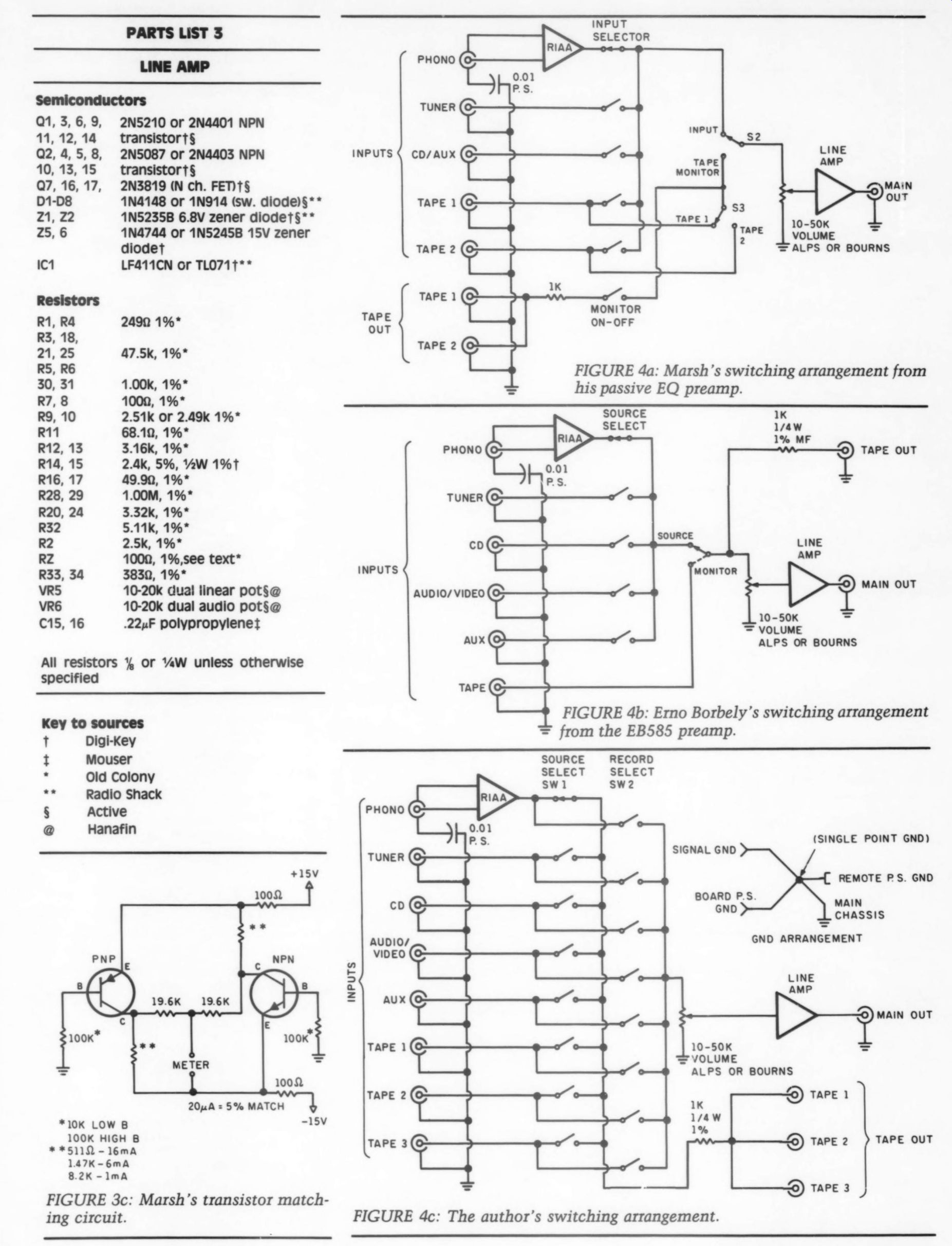
I am presently using the Borbely EB 585 phono sections in my preamp. Be fore beginning to build yours, decide what sort of switching arrangement you require. Some examples are given in Fig. 4. I'm now using configuration ‘C ’ which has only one switch con tact in the signal path. If the number of signal path contacts does not concern you, you may want to consider an external processor loop for equalizers, expanders, and so on (Fig. de).
The line amp circuit I describe is also a good choice for active crossover projects. (Fig. 10). Also you will notice in the schematic and the parts list a resistor designated ‘RZ. ’ This value can be changed to suit different applications. For example, if the line amp is to be used as part of an active crossover, it could be part of the filter network.
In most applications, the 100 ohm value listed will work well.
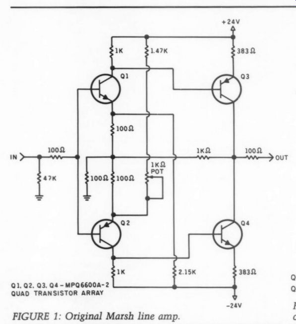
FIGURE 1: Original Marsh line amp.
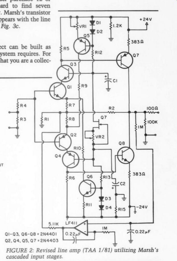
FIGURE 2: Revised line amp (TAA 1/81) utilizing Marsh's cascaded input stages.
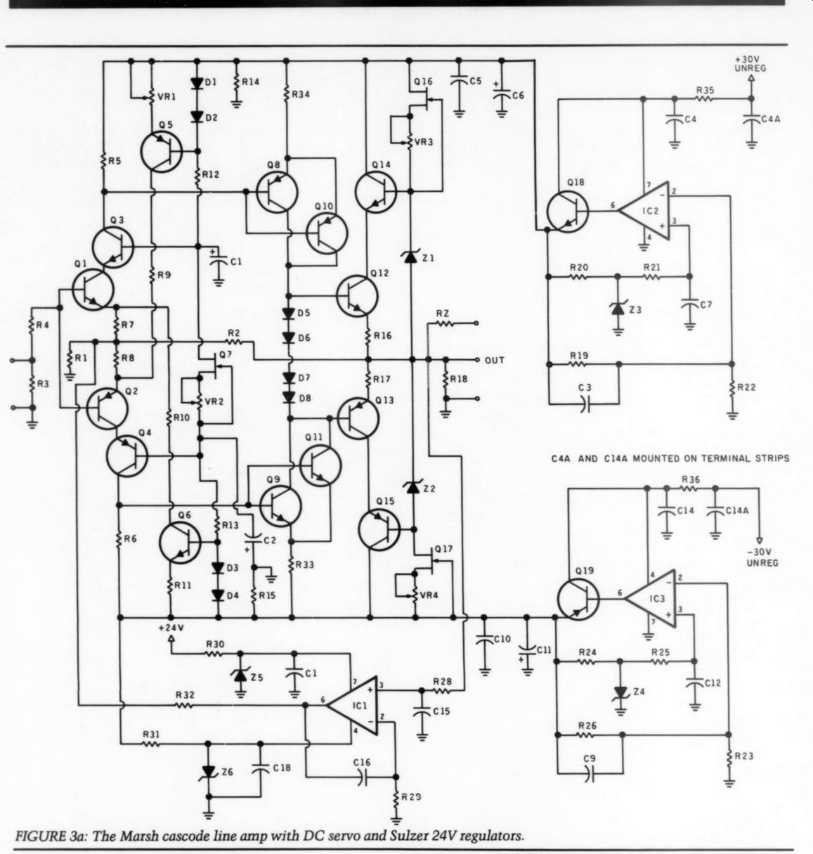
FIGURE 3a: The Marsh cascode line amp with DC servo and Sulzer 24V regulators.
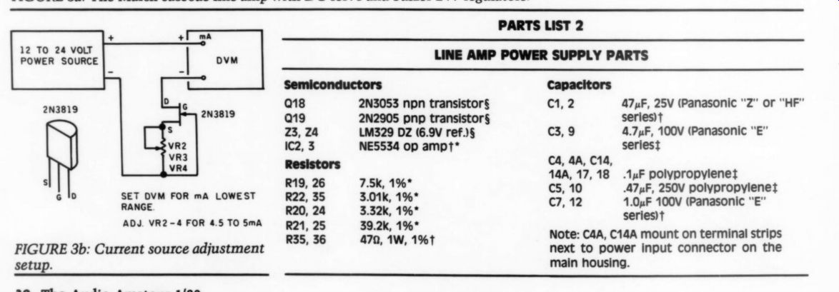
FIGURE 3b: Current source adjustment setup.
---------------
PARTS LIST 2--LINE AMP POWER SUPPLY PARTS
Semiconductors
2N3053 npn transistors
2N2905 pnp transistor
LM329 DZ (6.9V ref. NES534 op amp 7.5K 1% ’ 3.01k, 1% ’ 3.32k 1% ’ 1 39.2k, 1% ’ 479, 1W, 1%1
Capacitors
eh, 2 47,F, 25V Panasonic ‘Z ’ or ‘HF ’ series
C39 4.7yF, 100V (Panasonic ‘E ’ series
C4, 4A, C14, 14A, 17, 18 uF polypropylenes
Cs, 10 .47uF, 250V polypropylene
C2, 12 1.0xF 100V (Panasonic ‘E ’ series)
Note: C4A, C14A mount on terminal strips next to power input connector on the main housing.
-------------------
PART LIST 3--Line AMP
Semiconductors Q1,3,6,9, 2N5210 or 2N4401 NPN 11, 12,14 transistor
Q2,4,5,8 2N5087 or 2N4403 NPN 10, 13,15 transistor Q7,16,17, 2N3819 (N ch. FE1§ D108 1N4148 or 1N914 (sw. diode) ** 21,22 1N52358 6.8V zener diode 25, 6 1N4744 or 1N52458B 15V zener diode
IC1 LF411CN or TLO71t** R1, R4 2490 1%* R3, 18, 21,25 47.5k, 1% ’ RS, R6 30, 31 1.00k, 1%* R7, 8 1000, 1%* R9, 10 2.51k or 2.49k 1% ’ R11 68.10, 1%* R12, 13 3.16K, 1% ’ Resistors R14, 15 2.4K, 5%, YaW 1% R16, 17 49.90, 1% ’ R28, 29 1.00M, 1%* R20, 24 3.32k, 1% ’ R32 511k, 1% ’ R2 2.5k, 1% ’ RZ 1000, 1%,see text ’ R33, 34 3830, 1%* VRS 10-20k dual linear pot VR6 10-20k dual audio pot§@ C15, 16 .22,F polypropylene All resistors % or %W unless otherwise specified
Digi-Key Mouser Old Colony Radio Shack Active Hanafin
--------------------
FIGURE 3c: Marsh's transistor matching circuit.
FIGURE 4a: Marsh's switching arrangement from his passive EQ preamp.
FIGURE 4b: Erno Borbely's switching arrangement from the EB585 preamp.
FIGURE 4c: The author's switching arrangement.
--------------------------------
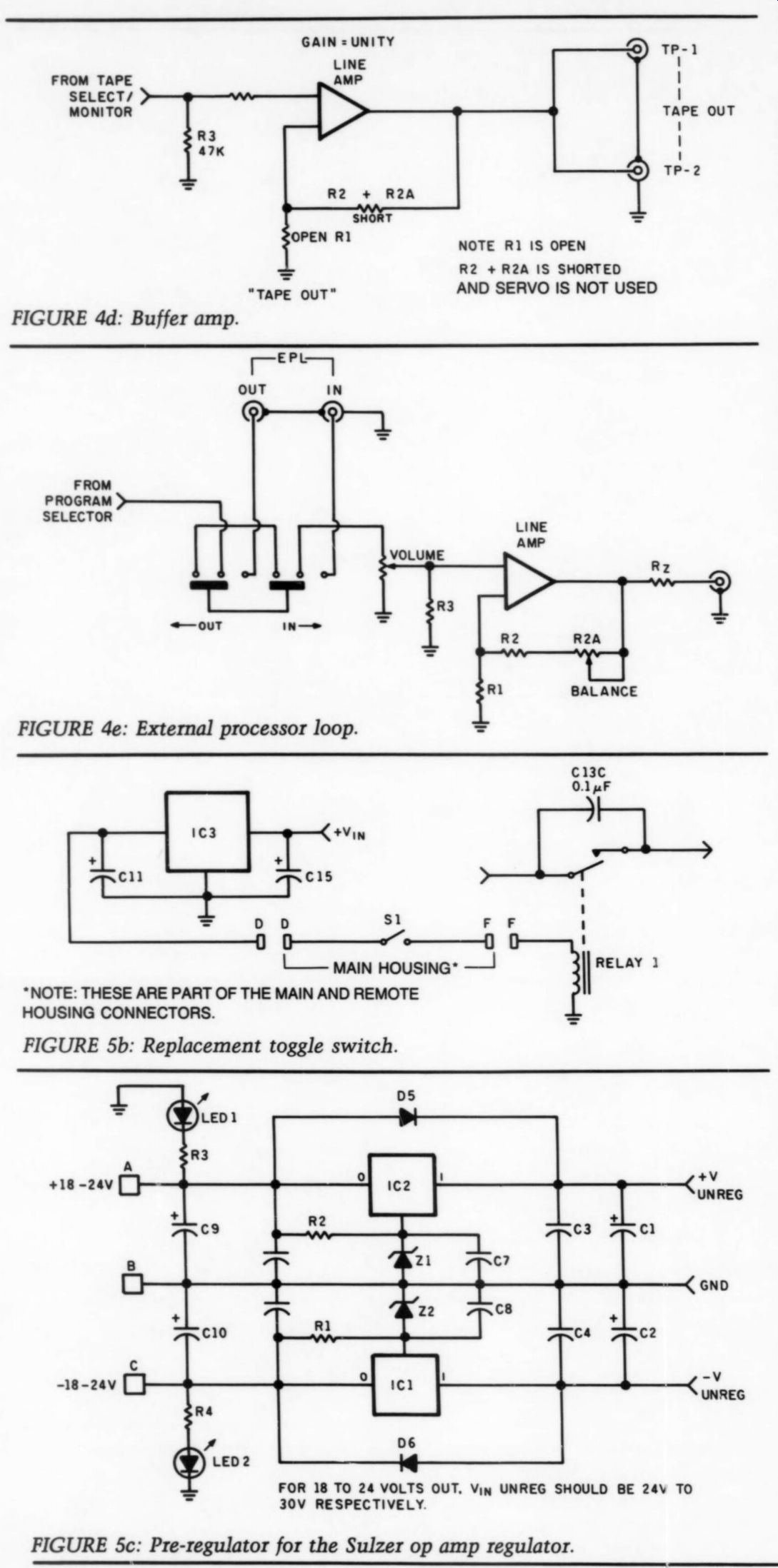
FIGURE 4d: Buffer amp. FIGURE 4e: External processor loop. FIGURE 5b: Replacement toggle switch.
‘NOTE: THESE ARE PART OF THE MAIN AND REMOTE
HOUSING CONNECTORS.
FIGURE 5c: Pre-regulator for the Sulzer op amp regulator.
------------------------
PARTS LIST 1---REMOTE POWER SUPPLY
Semiconductors
1 2N2219A transistor
D1, D7 1N4002 diode 21, 22 1N5248B zener diode
IC1 LM337 regulator (for other power supply applications)
IC2 LM317 regulator (for other power supply applications)
IC3, ICA LM7812 12V regulator
ICS 4011 quad NAND gate
Rectifier 1-100 PIV bridge rectifier
LEDs 1,2,3 Radio Shack (276-041)
Resistors R1, R2 1210 VaW, 1% R3, R4 1.5k, vaW, 5% R6, R7 100k, YaW, 5% R8 5100, aW, 5%
Capacitors
C1, 2,9 10 4,700 50V (Panasonic ‘TS ’ series) ck 4 AuF, 250V polypropylene Cc 7,8 47uF 250V (Panasonic ‘E ’ series)t C5, 6 10xF, 100V (Panasonic ‘LS ’ series) t c11 10xF 35V (Panasonic ‘LS ’ series) C13 (A,B,00 .1xF 250V ceramic disk c14 220xF, 25V (Panasonic ‘LS ’ series) C15 2,200F, 25V (Panasonic ‘LS ’ series) Transformers
2 25V, 1A s 18v, 500mA
-----------------------
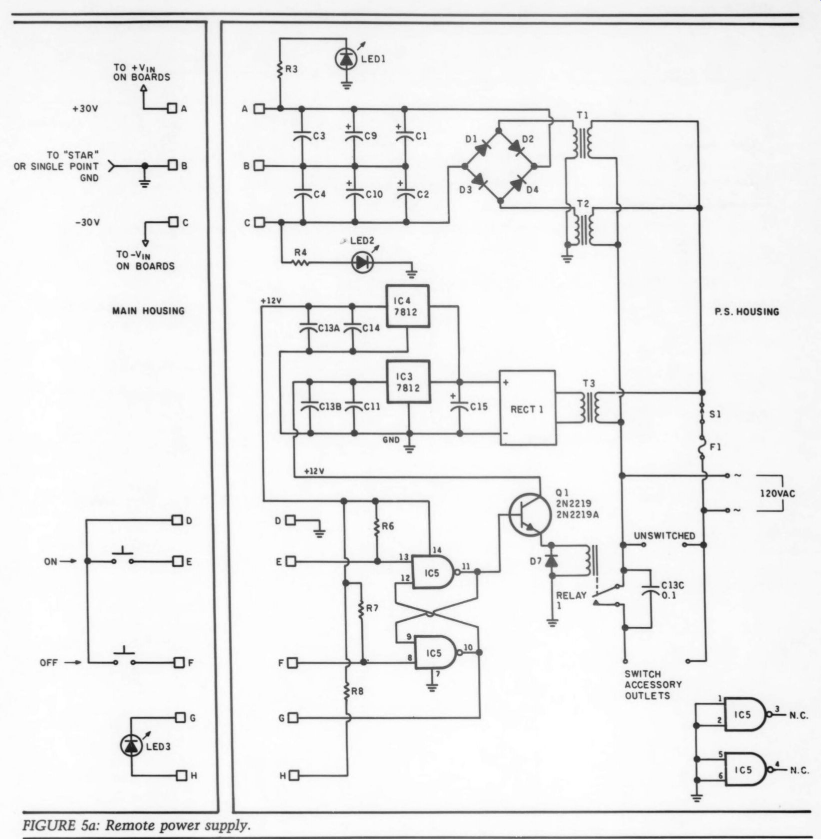
FIGURE 5a: Remote power supply.
Basic Configuration
I built my version as two units. One houses the switching and audio sections, the other an unregulated +30V DC power supply. The power supply unit contains switching for the AC power, filtering for the unregulated DC and an electronic switch that controls the AC switching relay (Fig. 5a). The DC power to the audio circuits is normally on. Only the AC power to the rest of the system via the remote power supply unit is switched on or off. A master switch for controlling the DC is provided for testing purposes or if the system will be off for an extended period. The relay for the AC is controlled by a set/reset flip/flop and transistor driver. The basic circuit came from an article printed in Popular Electronics in the 1981 Experimenters Handbook.
If you would like to forgo the electronic switch, then a simple toggle switch can replace IC4, ICS, R6, R7 and Q1 on the power supply board. See the remote power supply schematic for wiring details (Fig. 5b).
The remote power supply board may also be modified to act as a preregulator for Sulzer type regulators ’ (Fig. 5c) that supply 15-18V. A stuffing guide and parts list is supplied for this change as well (Fig. 7). Each line amp board has individual Sulzer regulators to supply the necessary + 24V for the line amps.
A shielded multiconductor cable connects the main and remote power supply sections.
Power Supply Construction
Building the project is fairly straightforward. You will find a Parts List and sup pliers to make obtaining parts reason ably easy.
Begin construction with the power supply circuit board, Fig. 6a. The power supply unit will be needed to test the line amp boards. Assemble the power supply board according to Parts List #1 and the stuffing guide in Fig. 6b. Install and wire the transformers, power sup ply board, fuse holders and so on, to the power supply chassis. Temporarily wire a 1k, %AW resistor across the positive supply. Do the same for the negative supply as well. Double-check all your wiring and parts placement. If all is well, power up and check the voltage at the points indicated in Figs. 5 and 6, or 7. The voltage should be about 30-34V. [See TAA 1/88 for an upgraded version of the supply.-Ed.]| Line Amp Locate the transistors in Parts List #2.
Using Marsh's matching circuit (Fig. 3c) find a total of seven matched PNP NPN pairs for each channel. Put these aside for now. Find three FETs, Q7, Q16, Q17 and three trimpots VR2, 3, and 4. These parts will make up the equivalent of a current diode. Find a breadboard socket, install the FETs and trimpots as shown in Fig. 5. It's also possible to assemble these onto the circuit board and trim them into place.
Apply 12-24V to the points shown. Set your meter to mA and adjust the trim pots for a reading of 4.5-5.0mA. Ideally you should try for 4.7mA. Once the setting is made, fix the trimpot adjustment with silicone rubber sealer (RTV).
If a breadboard socket is used to make
---------
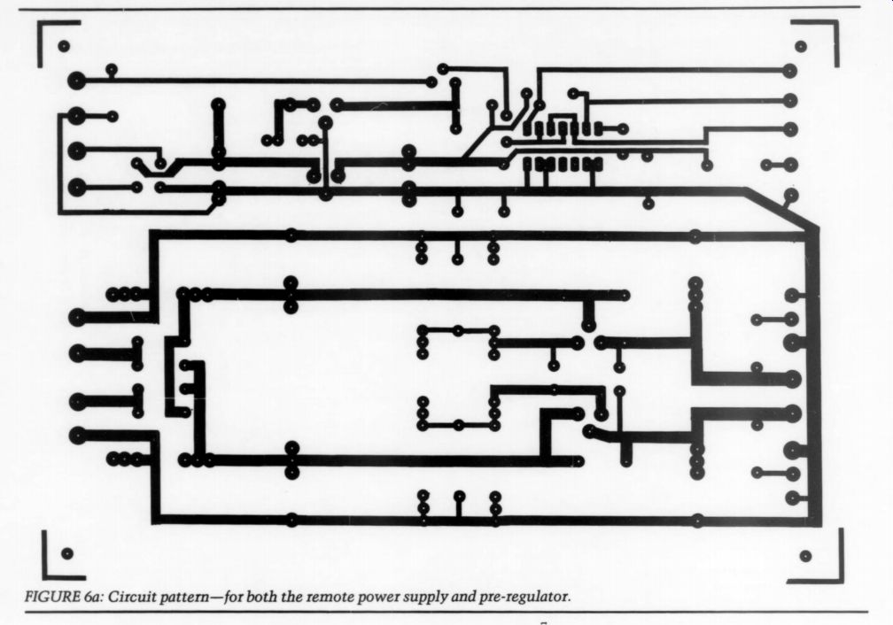
FIGURE 6a: Circuit pattern-for both the remote power supply and pre-regulator.
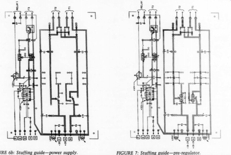
FIGURE 6b: Stuffing guide-power supply.
FIGURE 7: Stuffing guide- pre-regulator.
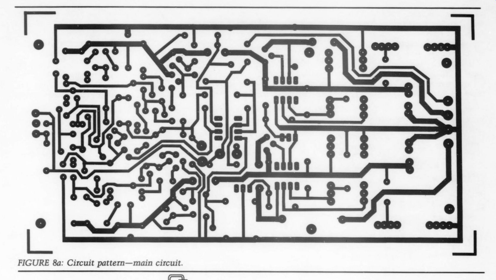
FIGURE 8a
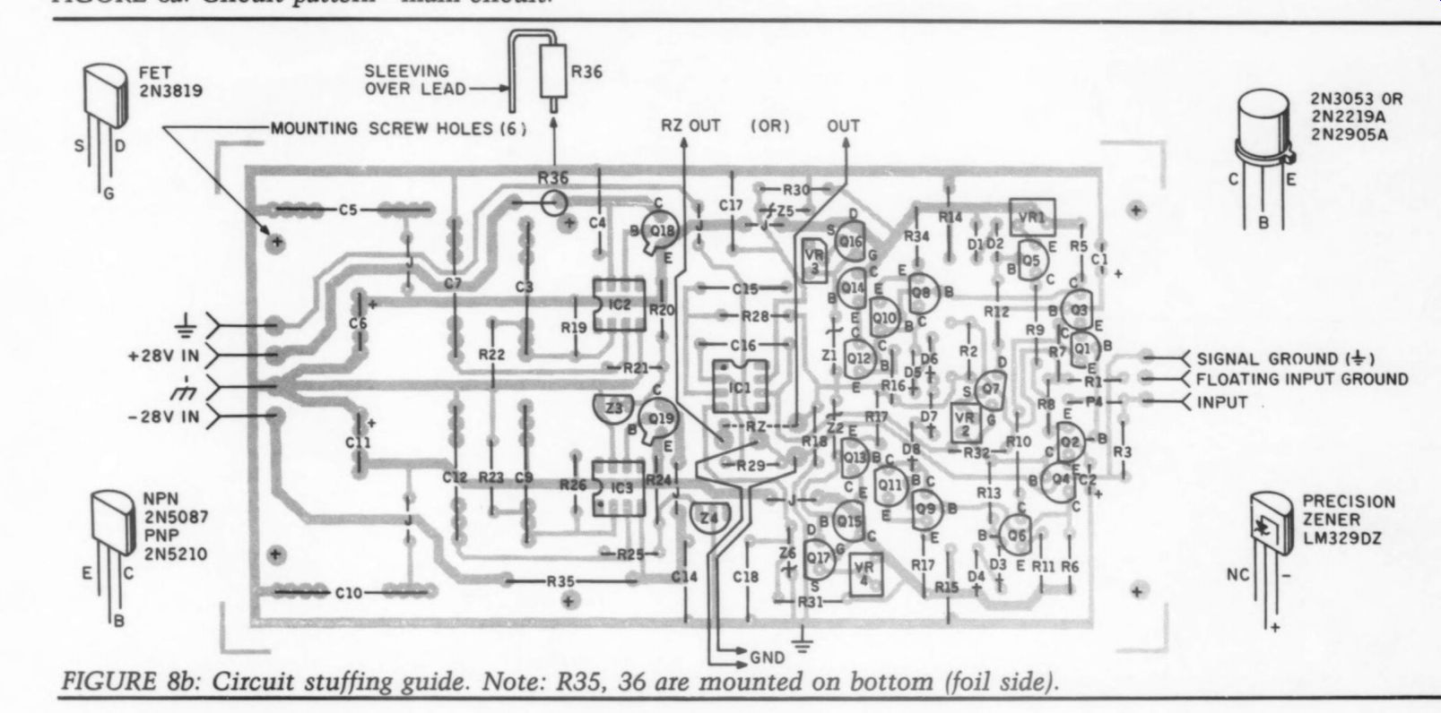
FIGURE 8b: Circuit stuffing guide. Note: R35, 36 are mounted on bottom (foil side).
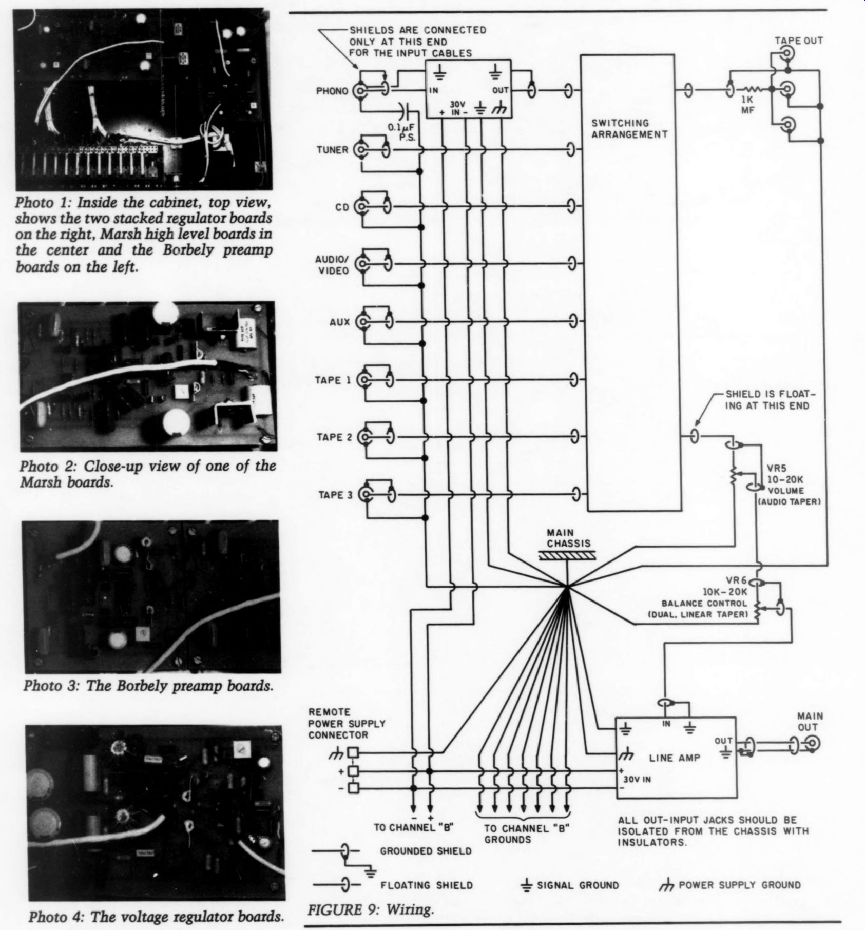
Photo 1: Inside the cabinet, top view, shows the two stacked regulator boards on the right, Marsh high level boards in the center and the Borbely preamp boards on the left.
Photo 2: Close-up view of one of the Marsh boards.
Photo 3: The Borbely preamp boards.
Photo 4: The voltage regulator boards.
FIGURE 9: Wiring.
FIGURE 10: Active crossover. Servos won't operate in unity gain configuration (see equation). To get 24dB, cascade two 12dB/octave; for 36dB, cascade two 18dB/octave; see Bullock's crossover article (SB 3/85).
-------------
... the trim adjustments you may now in stall these parts on the line amp circuit board. Be sure to keep each FET/pot pair from being separated. Use fixed trimming resistors in place of the trim pots if you have a good selection on hand in the 3300 to 2k range.
Now assemble the on-board regulators using Parts List #3 (Fig. 8a). Once you have completed this assembly, check it by applying DC from the re mote power supply and checking the regulator outputs. Your reading should be +24V. If all is well, then assemble the remainder of the line amp (Fig. 8b).
Do not install IC1 just yet. After completing the board again apply DC to the line amp and recheck the regulator outputs. If everything checks out, then connect a voltmeter to the line amp output. Ground the input to the line amp. Vary VR1 and verify that any DC can be brought close to zero volts.
With this last test completed, begin final assembly of the project. You may do the final offset adjustment later. Be sure to pay attention to proper wiring techniques (Fig. 9). You may find some of the past ‘POOGE’ articles in TAA helpful. If you have the patience to carefully install it, I recommend Mogami wire/cable for internal wiring as well as for interconnects.
I made my chassis from 18-gauge aluminum cut to overall size by a sheet metal shop and then formed in a small sheet metal break. Do all metal cutting and drilling before doing any painting and/or labeling. Install and wire the controls and connectors and then the circuit boards. Check for any wiring errors and then proceed to power up the unit. Allow 15 minutes for warmup.
Attach a DC voltmeter to the line amp output and again ground the line amp input. Now, adjust VR1 so the DC offset is close to zero (within 3mV).
Power your unit for about one hour, periodically checking and readjusting if required. This completes the DC offset adjustment. Now install IC1 after removing the power. Restore power and check DC offset again. It should be within +5mV. This completes your system check. Your preamp is now ready for installation.
Conclusion
This project has taken over one year to construct. I hope that by using my list of vendors, you can complete the en tire project within a month or two. Be sure to double-check all of your work and test procedures. I'm sure you will find the results well worth the effort.
Presently I'm investigating Mr. Marsh's claim that the basic circuit will work well in a CD player. I will let you know what I come up with. It should be interesting.
REFERENCES
1. Marsh, R.N., ‘'A Passively Equalized Phono Preamp,' TAA 3/80, pp. 18-21.
2. Sulzer, M., ‘A High Quality Power Supply Regulator for Operational Amplifier Preamplifiers, ’' TAA 2/80, p. 8.
3. Borbely, E., 'New Devices for Audio from National Semiconductor,' TAA 5/83, a
4. Borbely, E., The Borbely Preamp, Part 1 TAA 4/85, p. 7.
5. Marsh, R.N., ‘A Passively Equalized Phono Preamp,’ TAA 3/80, p. 8.
6. Marsh, R.N., 'A Preamp for Moving Coil Cartridges,’ TAA 1/82, p. 7.
7. Jung, W., and D. White, 'A PAT-5 Modification,’ TAA 1/78, p. 7.
8. Jung, W., and D. White, ‘The PAT-5/ WIJ-1A,’ TAA 3/79, p. 5.
9. Lampton, M. and D. Zukauckas, 'A Low Distortion IC Preamplifier Control Unit,’ TAA 1/79, p. 5.
10. Roberts, J., ‘Build a High Performance Phono Preamplifier,’ Popular Electronics, March 1981, p. 79.
11. Roberts, J., ‘A Preeminent Preamp, ’ TAA 3/85, p. 16.
PARTS DISTRIBUTORS
Active Electronics PO Box 9100 Westboro, MA 01581 Digi-Key Corp.
PO Box 677 Thief River Falls, MN 56701 (800) 344-4539
Mouser Electronics 11433 Woodside Ave Santee, CA 92071 (619) 449-2222
Mouser Electronics 2401 Highway 287 North Mansfield, TX 76063 (817) 483-4422
Old Colony Sound Lab PO Box 243 Peterborough, NH 03458 (603) 924-6371
Radio Shack If there is sufficient interest Old Colony will offer boards and a kit of parts for this project. Use Fast Reply #50 for a parts kit and Fast Reply #51 for circuit boards only.
-------------------
Also see: