MANUFACTURER'S SPECIFICATIONS:
Audio Output: up to 6V rms into 10k ohms.
Frequency Response: 5 Hz to 125 kHz ± 0.5 dB; 2 Hz to 250 kHz ± 1.0 dB. Harmonic Distortion: 6V output, 10 to 30,000 Hz, less than .05%; 2V output, less than residual of test equipment. IM Distortion: equivalent 6V rms, less than .05%.
Sensitivity (for 2V output); Phono 1 and Phono 2, 1.5 mV; Aux 1 and Aux 2, 150 mV; Aux 3, 300 mV. Noise (unweighted); Phono inputs (10 mV reference) 65 dB below 6V out; high level, (vol. at max.) 80 dB below 6V out; residual (vol. at min.) 90 dB below 6V out.
Input Impedance: phono, 47 k ohms; aux, 20k ohms.
Output Impedance: 500 ohms.
Recommended Load: 10k ohms or more.
Phono Overload: greater than 115 mV.
Audio Equalizers: ± 12 dB at 60, 320, 1000, 5000, and 12,000 Hz.
Price: $295.00.
One of the disadvantages of the separate preamp and power amplifier, as compared toe receiver, for example, is that the user does not have a low impedance phono jack on the control panel, and he is not able to switch speakers as readily. The Citation Eleven has eliminated this problem by the simple expedient of bringing the speaker leads to the back of the preamp, along with the outputs from the power amplifier. Thus aside from one six-foot cable for outputs and two shielded cables for inputs, which go between the preamp and the power amplifier, all connections are made at the rear of the preamp. This even includes three switched convenience outlets to accommodate the power amplifier, tuner, and tape recorder, and a fourth unswitched outlet for the phono turntable-a recommended practice to avoid the possibility of developing a flat on the idler if the unit is turned off at other than its own switching which also retracts the idler.
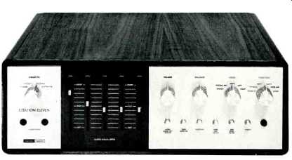
The front panel is separated into three sections at the left is the speaker system switch and the two phone jacks; at the center section are the five slide type equalizer controls; and at the right are four knobs controlling volume, balance, mode, and function. The mode switch provides five positions-stereo, stereo reverse, mono, left, and right.
The function switch has positions for phono 1, phono 2, tuner, and three "aux" inputs. Below the knobs are six metal push-push switch buttons: equalizer defeat, tape monitor 1, tape monitor 2, hi-cut, lo-cut, and power, with a pilot light to the right of the last button indicating when power is on.
The rear panel is just full of connectors. At the right is a five-terminal socket which accepts the plug carrying the power amplifier output leads through the six-foot cable. Below this socket are two vertical terminal strips, one for each of two speaker systems. Each strip has four barrier terminals-left "hot," left common, right common, and right "hot," making the connecting of the speaker systems a simple and foolproof operation without much chance of shorting the leads. Internally, this section is separately shielded, with the selector switch way to the back, and the leads to the phone jacks are shielded and run along the chassis base.
The dropping resistors for the phones are 330-ohm, 5-watt units. The switch has four positions-phones only, system 1 only, system 2 only, and systems 1 and 2. When the speaker systems are on, the phone jacks are switched off.
Next on the rear panel are four convenience outlets-three are black and are switched, while the fourth one, which is not switched, is white. Below these outlets are the line cord and the fuse holder. Next there are twelve pairs of phono jacks to accommodate the inputs and outputs. Two pairs are required for the low-level phono inputs, and two pairs are provided for the main outputs. Two more pairs are provided for tape recorder outputs, with neither being affected by the equalizer or filter controls on the front panel. Then there are two pairs for tape monitor 1 and 2, and the three pairs for aux 1, 2, and 3, with a twelfth pair accommodating the tuner. Thus it can be seen that considerable flexibility is built into the Citation Eleven.
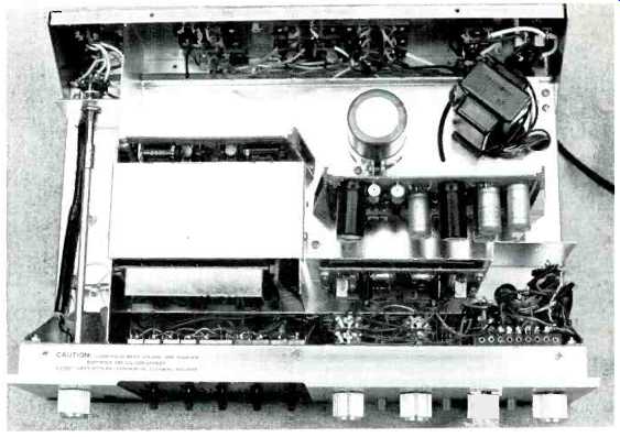
Fig. 1--Showing top view.
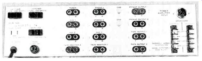
Fig. 2-Rear panel; note the four a.c. outlets.
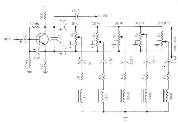
Fig. 3--Showing circuit of the audio equalizer which uses only one transistor
per channel. There are five slide controls and five resonant circuits.
Circuit Description
The circuitry is fairly simple, using two transistors in each channel for the low-level phono inputs to provide RIAA equalization and enough gain to bring the signal up to the same level as the high-level inputs. Following the tape-monitor switching and the hi- and lo-cut filters, the signal from each channel is fed to the base of a transistor which has equal collector and emitter resistors, and thus is a unity-gain device in the "flat" position of the equalizer controls. The two outputs-collector and emitter-are fed through large capacitors to the opposite ends of the five equalizer controls, each having a value of 50,000 ohms, and with each center-tapped and connected to ground as shown in Fig. 3. The arms of the five pots are connected through coils and capacitors resonating at the five specified frequencies--60, 320, 1000, 5000, and 12,000 Hz--along with series resistors to control the sharpness. When the arm of any pot is at the collector end, the resonant circuit shunts the signal to ground at its resonant frequency.
When the arm is at the emitter end of the pot, the shunting of the resonant circuit across the emitter resistor increases the gain of the stage, and thus boosts the signal, at the frequency of resonance. This is a very simple circuit, requiring a minimum of parts, but it does involve inductances, which are naturally susceptible to hum pickup.
Consequently, they are doubly shielded to avoid this possibility, and the efficacy of the shielding is shown by the low noise level of the preamp-better than 80 dB below 6 volts out. The equalizer defeat switch bypasses this circuit, and ensures flat response, also making it possible to compare the effect of control settings instantaneously.
The output section of the preamp consists of a feedback pair in each channel, preceded by a group of three FET's arranged so as to prevent a "thump" whenever the preamp is turned on. The drain and source of one FET are connected across the high-impedance input to each output amplifier, and when the gate-to-source voltage is zero-as it is when the preamp is off-the resistance between drain and source is of the order of 200 ohms, thus effectively shorting out the signal. When the preamp is turned on, a control voltage is fed to the gate through a time delay circuit and the drain-to-source resistance rises to several hundred megohms, thus removing the short and allowing the signal to pass unaltered.
The time constant of the delay circuit is approximately 20 seconds, so the unit "warms up" slowly, avoiding any clicks or thumps in the output. The third FET serves to feed the control voltages to the first two.
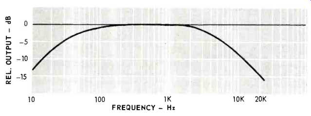
Fig. 4—High- and low-pass filter characteristics.
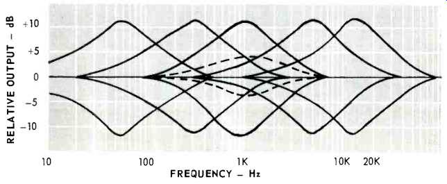
Fig. 5--Characteristics of the Audio Equalizers. The dashed curve shows
the 1000 Hz equalizer in mid-position. All others are at maximum boost and
cut positions.
Performance
The Citation Eleven satisfies its specifications excellently. The curves of the audio equalizer section are shown in a composite in Fig. 4. These curves show the effects of each of the five controls separately at both maximum boost and maximum cut positions. An intermediate setting of the control results in the dashed curve shown for the 1000-Hz position, and others are similar. To effect a certain curve, one may boost one of the five frequencies and cut the next, for example, and if every possible combination were plotted, it would take several pages for the curves alone.
Suffice that practically any desired response curve can be obtained with the controls in the various positions.
Simply add and subtract the curves and see the possibilities for yourself.
The curves track within ± 1 dB throughout their ranges, and provide a maximum boost or cut of 12 dB at each of the five frequencies. Similarly, the phono circuits follow the RIAA curve within ± 1 dB from 20 to 20,000 Hz, and curves for both phono positions are identical, naturally, as are those for both channels. The lo- and hi-cut curves are shown in Fig. 5. The maximum rated output for the preamp is 6 volts, but clipping does not occur until a 12 volt output is reached. Phono overload is a comfortable 112 mV, which should accommodate the loudest rock records, even when played with a high-output cartridge. At 6 volts output, IM distortion measured a miniscule .04%, and THD was under .05% at 6 volts, and below residual at 2 volts, which means that distortion is essentially not a factor in the output. The signal-to-noise ratio measured 62 dB on phono (referred to a 10-mV signal and a 6-volt output). With the volume control at maximum, S/N was 82 dB, and with the volume control at minimum, S/N was 93 dB. These figures transcend the term "excellent" in every particular. Even the two sections of the volume control track within ± 0.5 dB, which is remarkable.
Having made all the measurements, we were champing at the bit to try it out.
We have been using the Citation Twelve as a power amplifier for some months, and from the moment it was put into service, we noted a definite improvement in our sound quality. The Eleven does away with the need for any frequency shaping devices, since it has practically all that anyone could desire.
One can change the quality of male voices, for example, and it is likely that you could have all announcers sound almost the same if you wanted to. With music, you can correct for recording mis-equalization, if it exists, or you can add your own. You can compensate for room acoustics to a remarkable degree, increasing the bass to make up for speaker deficiencies, and boosting or cutting the highs-extreme or middle-to make up for room furnishings. In short, there is very little that you cannot do with the Citation Eleven. It is a worthy addition to the already distinguished reputation that the name Citation has achieved over the many years since they first made their appearance.
-C.G. McP.
(Audio magazine, Jan 1971)
Also see:
Harman/Kardon Citation 16 Basic Amplifier (Equip. Profile, Dec. 1976)
Harman-Kardon Citation Twelve Basic Power Amplifier (Equip. Profile, May 1970)
Harman/Kardon Citation Twenty-Five Preamp (Mar. 1989)
Harman-Kardon Citation Fourteen Stereo FM Tuner (Dec. 1972)
Harman-Kardon Citation 13 Speaker System (May 1972)
= = = =