MANUFACTURER'S SPECIFICATIONS:
Continuous Power Output: 120 W, both channels driven simultaneously.
THD: Less than 0.2%, 20-20,000 Hz, into 8-ohm load. IM: Lass than 0.15% at all power levels, 60 and 6000 Hz, 4:1. Hum and Noise: Better than 100 dB below 60 W.
Frequency Response: 1 Hz to 70 kHz, ±1. dB at normal listening level; 0.5 Hz to 100 kHz ±1 dB.
Power Bandwidth: 5 Hz to 35 kHz; Dimensions: 5(6" H x 123(6" W x 12%" D (complete with metal cage).
Weight: 30 lbs.
Price: $295 wired; $225.00 in kit form.
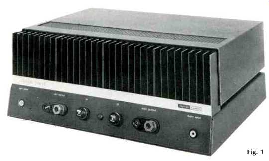
Harman-Kardon has done it again. That is to say, they have brought out another Citation. After a long absence from the marketplace, Citation Twelve is the first of a new generation of solid-state equipment, and it lives up to the reputation made by the earlier Citations.
Listed as an amplifier, the Citation Twelve is actually two separate amplifiers on the same chassis, which they share.
There are two power transformers, two separate silicon bridge rectifiers, and separate filter systems. Both transformers are wound with split primaries which are normally connected in parallel for 117 volt operation, but which may be rewired in series for use on 220-240-volt lines.
The primary circuits are protected by a line fuse, and by a thermal circuit breaker which is in contact with one of the output transistor cases and which opens' the primary circuit if the transistor case should get hotter than 80°C. In addition to sharing the chassis, the two amplifiers share a printed-circuit board on which the stages prior to the output transistors are mounted, but at no place are they interconnected. In fact, the only place where the two amplifiers are connected together is at the ground, and even there the right channel is isolated from chassis ground by a 10-ohm resistor to avoid hum loops. The printed-circuit board is fitted with twenty-eight Molex connector sockets which mate with pins mounted in five nylon connector blocks installed in the chassis openings. The two amplifier circuits are essentially mirror images of each other, so the printed circuit board could be inserted either way with no effect on performance. The board is held down by two nylon "A" frames, which may be removed if the circuit board is to be unplugged for service reasons.
The four output transistors--two per channel--are mounted on four heavy-duty heat sinks which serve as the front of the unit, with the dress panel with input and output connections, the power-line fuse posts, and the pilot light. The power cord enters from the rear chassis apron. Figure 2 shows the amplifier with the cover removed, while Fig. 3 shows the underside. Note the separate ground buses--one for each channel--running from the rear of the chassis forward and towards the sides where they provide ground connections for the input jacks. The physical connection between the ground buses and the chassis are taken from the center of the bus running between the filter capacitors so as to be at the exact electrical center of each of the circuits to minimize hum.
The Circuit
Electrically, the circuit of the Citation Twelve is similar to an operational amplifier, and it is likely that this configuration will be seen in more and more amplifiers in the future. It employs a balanced-to-ground circuit, with positive and negative supply voltages, so that the output lead is at ground potential, thus eliminating the need for series output capacitors. The only capacitor in the signal circuit is at the input, which accounts for the exceptional low-frequency performance of the amplifier. The input signal is fed to one base of a differential transistor--a dual PNP type--and feedback is routed to the other base, resulting in a comparator circuit which balances automatically for zero d.c. offset voltage at the output terminals. The signal from the differential amplifier is fed to a pre driver, which feeds the PNP driver directly and the NPN driver through a bias network which has its heat-sensing double-diode mounted on one of the heat sinks. Two test points are provided on each half of the circuit board to permit setting of idling current through the output transistors to a mere 30 mA. A potentiometer is mounted on the board for each channel to permit this adjustment. The complete schematic of one channel is shown in Fig. 7.
The output transistors are mounted on four separate heat sinks of husky dimensions. Each is 3 1/8 in. square, with nine 1 1/4-in. fins on one side of the 1/4-in. base plate, from which another 1/4-in. section projects 1 5/8 in. from the side opposite the fins. It is this projection on which the output transistors are mounted, along with the double diodes on two of the heat sinks, and with the line circuit breakers on the backs of the transistors on the other two sinks.
Construction
This observer had the opportunity to construct a Citation Twelve from a kit of parts, and had no difficulty at all. The Molex connector blocks snap into holes in the chassis. The constructor mounts the transformers and the filter capacitors, as well as the front-panel hardware. The circuit board involves the mounting of 34 resistors, 14 capacitors, 2 potentiometers, 2 r.f. chokes, 2 diodes, and 10 transistors, all of which can be done easily in less than two hours. Chassis assembly and wiring should not take more than eight hours, assuming some familiarity with construction, so for ten hours of work you can save $70.00 if you are so inclined.
Best of all, however, is that you will have an excellent product of which you can be proud, and you will have joined the elite of kit builders--those who have built Citations.
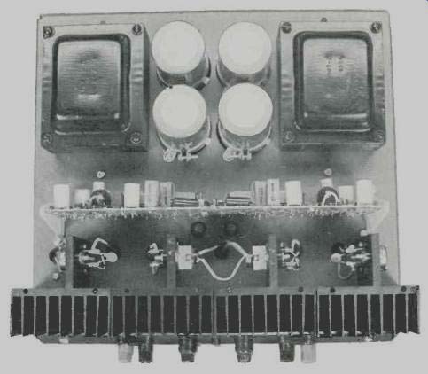
Fig. 2-View with cover removed
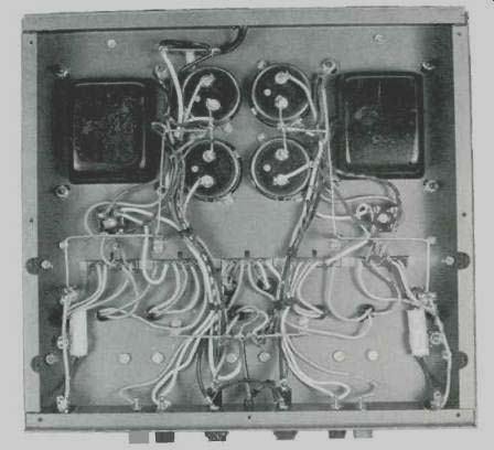
Fig. 3--Showing underneath. Note separate bus-bars.
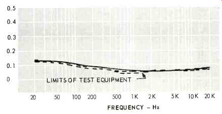
Fig. 4--Distortion vs Frequency
Performance
In practically every category, the Citation Twelve surpassed its specifications. We measured distortion at 60 watts at .06 percent, and at 70 watts we found THD was only 0.15 percent, while it reached 2.3 percent at 80 watts for a short while-then the output circuit breaker cut out, as would be expected.
Coming down the power scale, we found THD to be .06 percent all the way down to a 1-watt output. We measured more distortion at 20 Hz, but there was more residual at this frequency. At 5000, 10,000, and 20,000 Hz, we also found distortion to remain at .06 percent. We have heard of lower measurements on the Twelve, but those involve much more elaborate test equipment to get the residual down below the .04 percent, which we find in our equipment. Inter modulation distortion measured 0.1 percent át 60 watts and 0.2 at 1 watt. IM is normally higher at low levels than at rated output with solid-state amplifiers.
Crosstalk between channels was essentially un-measureable, since it was greater than 100 dB at 1000 Hz, and was 76 dB at 10,000 Hz. Frequency response was within ±1 dB from 1 Hz to 100 kHz, which is as good as anyone could want for audio applications. Hum and noise was better than 100 dB below rated output when the input jack was shorted, and 86 dB below rated output with the input jack open. Power Bandwidth measured 4 to 35,000 Hz, slightly better than specifications, and is shown in Fig. 6.
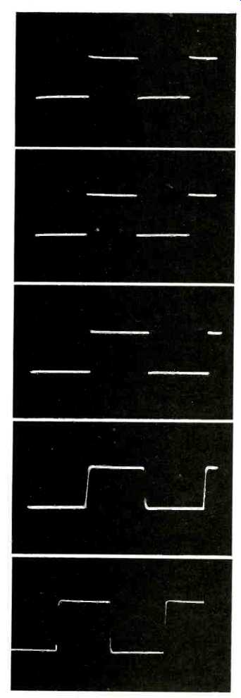
Fig. 5-Square-wave response. Reading from top, 20Hz, 100Hz, 1000Hz, 10,000Hz
and 20,000Hz.
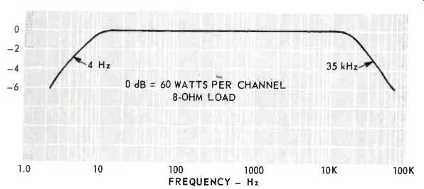
Fig. 6-Power Bandwidth curve
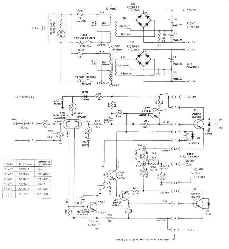
Fig. 7--Schematic of one channel and dual power supply.
With such exceptional low-frequency response, one would expect excellent square waves throughout the spectrum.
From 20 to 10,000 Hz, there is little difference in the square-wave response, as shown in Fig. 5. The pattern at 20,000 Hz shows a rise time of approximately 2µsec, which is exceptionally good.
The thermal cutout in the output line resembles a lantern flasher in appearance.
If the output current exceeds a safe value for the transistors, these devices open the output circuit, thus protecting from direct shorts. As soon as they cool down, the circuit is restored to normal. During our tests we were measuring a loudspeaker at fairly high levels-exceeding the acceptable output of the amplifier, apparently.
Consequently, we got a tone-burst effect from the speaker. The amplifier was not damaged in any way, and the measurements were made after this experience. The manufacturer recommends placing a 1-amp fuse in the speaker line at the speaker-not at the amplifier-for 8-ohm loudspeakers rated at up to 60 watts music power, and 1.5 amp. fuses in the lines to speakers rated from 80 to 200 watts music power. For 4-ohm speakers, fuses of 1.5 and 2.0 amps are recommended rating. This is deemed necessary power rating. This is deemed necessary by the manufacturer because the Citation Twelve is capable of a continuous output of 60 watts per channel of sine-wave power, which could certainly exceed the music power, and 1.5-amp. fuses in the dition, this 60-watt power extends down to below 20 Hz, and the simple removal of an input plug could put a loudspeaker out of commission. In these days of high-powered solid-state amplifiers, this is a precaution that might well be taken by the user of any one of them, but it is particularly important when the amplifier can deliver power to the lower frequencies. There are no tubes to saturate nor are there any transformers which have reduced efficiency at very low frequencies and thus help to protect against large bursts of current to the speakers.
Listening to the Citation Twelve is an enjoyable experience. Reproduction is clean and crisp, with good, solid lows. You are just not conscious of the amplifier at all. As we said about the first Citation amplifiers, you listen through the amplifiers to the original source. And we say it even more so with the Citation Twelve.
C. G. McP.
(Audio magazine, May 1970)
Also see:
Harman/Kardon Citation 16 Basic Amplifier (Equip. Profile, Dec. 1976)
Harman-Kardon "Citation Eleven" Stereo Preamp/Audio Equalizer (Jan. 1971)
Harman/Kardon Citation Twenty-Five Preamp (Mar. 1989)
Harman-Kardon Citation Fourteen Stereo FM Tuner (Dec. 1972)
Harman-Kardon Citation 13 Speaker System (May 1972)
= = = =