by Richard Modaferri
Until recently, there has existed no simple general method for designing selective minimum-phase, constant time delay filters. Since constant time delay filters are necessary for low distortion FM signal transmission and minimum-phase filters are easy to construct and align, a general method for locating the poles or resonant frequencies of minimum phase constant time delay filters would be useful. The method presented here uses a FORTRAN computer program to realize a new class of highly selective minimum-phase, constant time delay filters. Experimental FM tuners were constructed to test the new filter characteristic and will be discussed first. Two successful commercial designs, the McIntosh MR-77 and MR-78, will then be examined.
With the advent of stereo FM broadcasting, very stringent requirements have been set for the design of a high-fidelity receiver. In particular, one important aspect of FM receiver design, the i.f. amplifier delay characteristic, has been largely compromised in tuners and receivers intended for the consumer market. Typically, these circuits fall into a general stereotype consisting of limiter-amplifier stages separated by tuned circuits of insufficient selectivity, a sacrifice necessary in order to obtain reasonably constant time delay.
In seeking a means to improve upon the performance of FM i.f. amplifiers, a new linear-phase filter, the Rimo filter, has been devised. The filter designs are arrived at by computer solution (1). A brief discussion of the theory behind the computer solution follows, with some applications of this theory to commercial FM tuner designs.
One of these designs, the McIntosh MR-78, became the first tuner to achieve adjacent-channel reception capability. Variable-selectivity FM i.f. systems, including the MR-78, will be discussed in the final part of this paper. We begin with a treatment of some of the basic theoretical aspects of low-distortion, high-selectivity FM receiving systems.
I.f. Amplifier Bandpass Characteristics
First, the ordinary design approaches to the FM i.f. amplifier system were investigated. Both cascaded synchronously tuned and stagger-damped Bessel filter systems were tried and rejected due to poor selectivity. Another design approach effected a compromise by using a selective minimum phase filter characteristic (Butterworth) which had fair delay performance and enough selectivity to provide good alternate-channel reception. Adjacent-channel reception was not considered as the distortion expected would be too high.
The Butterworth tuner yielded acceptable performance and probably justifies the lack of initiative that has been evident in most commercial designs, which generally use some kind of flat-amplitude, minimum phase filter amplifier. However, the chronic problems of insufficient selectivity and excessive stereo IM distortion persisted in these designs, and new technology was needed to improve FM i.f. amplifier performance.
One of the well-known properties of a selective, flat-amplitude, minimum-phase filter is that the time delay increases from the midband toward the band edges. If a single-tuned circuit is now placed in cascade with the aforementioned filter and is tuned to its midband frequency, a crude sort of delay equalization will result as shown in Fig. 1.
The concept in Fig. 1 can be expanded. If the poles of a minimum-phase filter can be adjusted to give any desired amplitude shape, might not they also be adjusted to give any desired passband phase response while having high skirt selectivity? Would the passband response still be useful? If the pole locations of useful filters are determined, then a new approach to the FM i.f. amplifier design problem will be found.
The Rimo Filter
Presented here are a new class of minimum-phase FM i.f. filter. Rimo filters have nominally constant time delay within their passbands and rapidly degraded delay characteristics outside their passbands. The amplitude shape is rounded in the passband, with relatively high skirt selectivity. The pole locations for these filters are obtained by computer solution (1) and allow the design of a selective, low distortion, easily aligned FM i.f. amplifier.
The general computer program allows any number of poles from four to 20 to be placed in the upper-left half S-plane. Up to 10 may be fixed, and up to 10 are movable to positions yielding minimum delay error. For example, the designer may select five poles to yield his basic selectivity, add five movable poles, and locate the 10 poles of a "hybrid" Rimo filter. This filter will then have the minimum passband delay error, given the five fixed poles and the desired selectivity.
The designer could also choose no fixed poles and eight movable poles. This would yield a "pure" Rimo filter. Pure Rimo filters can give some simple high-performance designs. McIntosh's MR-77 an eight-pole pure Rimo filter made up from just four ordinary double-tuned i.f. transformers!
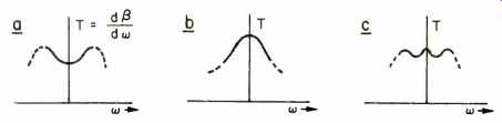
Fig. 1--Delay equalization of a bandpass filter. A) Time delay for a typical
bandpass filter with flat amplitude response. B) Time delay for a single tuned
circuit. C) Time delay with A) and B) connected in cascade. Solid part of curves
is the pass band, dotted part is the stopband.
Basic Theory
In order to obtain a linear-phase characteristic from an arbitrary number of upper-left poles in the S-plane, a computer program is required which will be automatic and convergent, i.e. the computer must place the poles into the one optimum constellation. The upper left poles always occur in conjugate pairs; the lower left poles are assumed, but do not explicitly exist in the computer program.
Given some S-plane poles, one can obtain minimum delay error by simply moving all of them out to infinity the resulting filter would be a cascade of open and short circuits! One avoids this trivial solution by specifying the mid-band time delay and holding this constant during execution of the program. This insures that the skirt selectivity will remain relatively constant and that the computer's action will concentrate on trading off in-band amplitude flatness with the band-center delay characteristic.
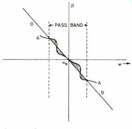
Fig. 2--Phase response of a bandpass filter having poor phase linearity. Line
A-A is the phase characteristic of the filter, B-B is a straight line tangent
to phase curve at midband frequency. The shaded area between A-A and B-B is
a measure of the phase error.
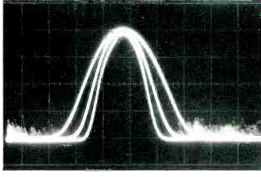
Fig. 3--I.f. response of an FM tuner using three Rimo filters in a three choice,
variable selectivity scheme (MR-78 prototype No. 1). (Scales are 100 kHz/div.,
20 dB/div.)
If one plots the phase response of a hypothetical narrow-band, minimum phase bandpass filter, and superimposes on this curve a straight line drawn tangent to the phase curve at the midband frequency, the results could appear as in Fig. 2. The shaded area between the curves of Fig. 2 is a measure of the delay error of the filter. If one can move the poles of the filter in such a way as to maximally reduce this shaded area, the filter will then have optimum delay characteristics.
With the computer program devised such that the shaded area near the center frequency, in Fig. 2 is minimized as poles are moved, the problem is solved, since a filter with straight line phase shift near its center frequency will also have constant time delay near its center frequency. By not trying to force the straight phase curve too far from the center frequency, one can hope to preserve the high skirt selectivity of the filter. It's a case of "having your cake and eating it too," and in practice, Rimo filters have remarkably constant time delay in the passband and plenty of selectivity in the skirts. The rounded top in the amplitude response takes some getting used to for those who like their FM tuners with a "square" i.f. passband shape, but when one operates a Rimo filter receiver, one never notices the i.f. passband shape. (Fig. 3.)
Effect of Nonlinear Phase Shift Upon FM Distortion
In order to establish the need for a linear-phase filter in an FM receiver, it becomes necessary to develop an analytical means for computing the signal distortion which would result from phase nonlinearities in transmission. Accurate computation of FM signal distortion is quite complex (8); this writer has derived a quasi-empirical relation (2) which is simple and gives useful engineering answers for typical FM receiver systems.
Even simplified FM distortion calculations require messy mathematics, so only the results will be discussed here. Table I tabulates the distortion and selectivity for two FM tuners, the author's early five-pole Butterworth (1962) and a later 10-pole Rimo (1965). The i.f. response and delay for these same tuners is shown in Fig. 4.
Besides having double the selectivity of the Butterworth filter, the Rimo has only one-half the distortion. Ten Butterworth poles arranged to yield 60-dB selectivity would have much greater distortion than either of the filters in Table I.
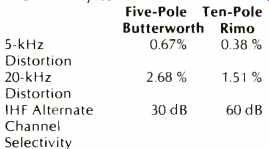
Table I--Computer third-harmonic distortion, before de-emphasis, for two FM
i.f. systems.
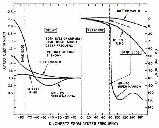
Fig. 4--Amplitude and delay characteristics for three FM tuner i.f. systems.
1) Author's early Butterworth tuner, c. 1962. 2) Author's 12-pole Rimo vacuum-tube
tuner, c. 1965. 3) MR-78 prototype No. 3, c. 1971.
Application of the Rimo Filter to the FM I.f. Amplifier
The real usefulness of the Rimo filter lies in its application to FM transmission. Ideal FM signals are sensitive to phase information only, and the linear-phase characteristic of Rimo filters make them particularly well suited to FM amplifier use. If an FM signal is passed through an i.f. system using these filters, the important phase information will suffer negligibly, while a good limiter will easily handle the moderate passband amplitude distortion. The high selectivity will effectively suppress alternate or even adjacent-channel signals.
Various Rimo filter tuners have been constructed by the author in the last 13 years, beginning with the original vacuum-tube model of 1965 (Fig. 5) and ending with the successful exploitation of the Rimo filter in the McIntosh MR-77 and MR-78 tuners. Also shown in Fig. 5 is an interesting battery-powered "MR-78" AM-FM radio prototype. This battery set has been backpacked and jeeped to mountain tops for endless and fascinating DX work. It will be the subject of a later construction article for ambitious readers.
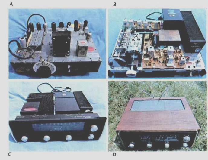
Fig. 5--Several of the author's experimental tuner prototypes. A) Vacuum tube
type, c. 1965, with the first Rimo filter. B) First MR-77. C) MR-77 No. 2,
c. 1969, with 10-pole Rimo filter. D) Battery-powered MR-78.
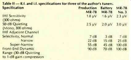
Table II R.f. and i.f. specifications for three of the author's tuners.
FM Reception Problems and Solutions
FM tuners should be able to accept the r.f. energy from an antenna and convert this energy into usable audio signals. Sounds simple stated this way, but to take each and every signal at the antenna and convert it to a noise and distortion-free audio output is extraordinarily difficult. Most tuners, even those costing thousands of dollars, ignore up to half of the theoretically usable signals at their antennas.
This writer's tuner designs have always emphasized the optimization of the tuner's ability to convert each signal present at the antenna into a useful audio signal. Crucial to this end is the proper design of the r.f. and i.f. circuitry. The two essential considerations are front-end dynamic range and i.f. selectivity.
Dynamic range operates in an FM tuner's front end exactly the same as it does in the more familiar phono preamp. Good dynamic range in both implies that tiny signals the little details are not obscured by the presence of much stronger signals.
Poor dynamic range in a tuner front end yields cross-modulation and spurious responses, which are really a kind of distortion, A phono preamp with the same poor dynamic range would mask orchestral detail and in general sound distorted.
I.f. selectivity is useful only up to the extent of the tuner's front-end dynamic range. For example, if the dynamic range is 100 dB, the useful maximum i.f. selectivity is also 100 dB. If one should graft the 100-dB i.f. filter onto a front end having only 50-dB dynamic range, then all signals 50 dB below the strongest one on the dial will be prone to spurious interference. Putting a poor front end ahead of a good i.f. amplifier is analogous to connecting a noisy and distorted phono preamp to a clean super-power amplifier.
The author's MR-78 prototype uses a special vacuum-tube r.f. front end and an eight-pole, four-zero crystal i.f. filter, along with 16 poles of Rimo i.f. filtering. Specifications are tabulated in Table II. This tuner has been field tested in some very difficult reception areas. Clear stereo signals come in on this MR-78 which are inaudible or unusable on any other commercially available tuner, even at the date of this writing (11).
McIntosh's commercially available MR-78 is only a little less "hot" than the third prototype. It's a bit more sensitive, with about half the maximum selectivity. The battery set is very sensitive for best results from its "rabbit ears" antenna. Some loss in front-end dynamic range and i.f. selectivity results from tradeoffs which maximize sensitivity and minimize battery drain.
An FM tuner with 100-dB IHF alternate-channel selectivity will not guarantee adjacent-channel reception. FM stations do not always radiate signals which are as much as 100 dB down in their adjacent channels. This is especially true for stations which use an SCA subchannel.
When the FCC adopted the standards concerning signal emissions of FM stations, the minimum adjacent channel selectivity of any FM receiver was considered to be only 6 dB (ref. 10, p. 785) !
Adjacent-channel reception was believed impossible when the FCC developed its technical standards on FM broadcasting. Today these standards have not been revised to keep up with the advances in receiver design. When surface-wave integratable filters become available in the near future, anyone will be able to market an inexpensive FM receiver with any amount of selectivity. Plastic portable radios with 100-dB adjacent-channel selectivity should cost no more than present-day sets.
Perhaps our call to alarm should be recognized. Adjacent-channel FM reception should be considered when new FM broadcast standards are written. This will become especially important with respect to discrete four channel broadcast systems, which will certainly aggravate the adjacent-channel reception problem. These systems contain high-energy, high-frequency modulation components that could spill over into the adjacent channel. Add an SCA subcarrier to a discrete four-channel modulation, and it may be economically and/or technically unfeasible to reduce adjacent-channel energy to a level 100 dB below carrier level.
Fortunately, many FM stations radiate a clean signal well in excess of FCC standards, at least with respect to side band energy distribution. Owners of selective FM receivers can use high selectivity in many cases. WTIC, 96.5, Hartford, Conn., radiates low adjacent-channel energy, permitting reception of WQXR, 96.3, New York City on an MR-78 (11).
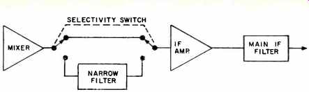
Fig. 6--Typical i.f. system layout for an FM tuner with two selectivity choices.
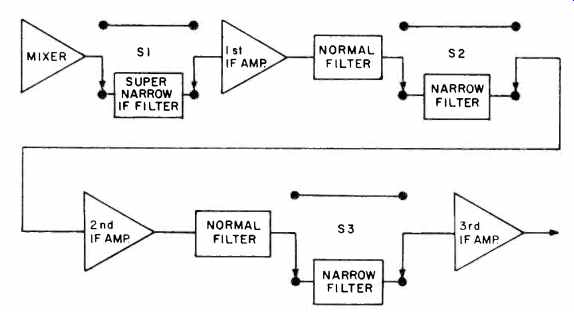
Fig. 7--MR-78 i.f. system. Super-narrow signal path is shown. For Narrow, Si
points up, bypassing the super-narrow filter. For Normal, all switches point
up, leaving only the Normal filters in the signal path.
MR-77, Variable Selectivity and the MR-78
We close with a historical treatment of the MR-77 and 78 designs and the application of this design process to the solution of the FM reception problem outlined previously.
The MR-77 grew out of the author's research at New Jersey Institute of Technology in the early 1960s. The MR-77 is a direct descendant of the early vacuum-tube tuner of 1965.
Selectivity was not uppermost in the author's mind at this time, so the MR 77 came to be a low-distortion tuner with good spurious response rejection and conventional selectivity. McIntosh customers soon began asking for a tuner which would receive adjacent channels. An MR-77 was taken to a difficult test location to try adjacent channel reception and it failed (11). An avid collector of old radios, this writer was inspired by one design concept commonly used in the "super" AM consoles of the 1930s, variable i.f. selectivity. I asked "Would this work in a modern FM tuner?" "Yes, it will," came the answer, "after a lot of development work." The McIntosh variable selectivity scheme, now being adapted in most "super" tuners, involves the switching into the signal path i.f. filters which add to the selectivity (Fig. 6). Figure 6 shows a tuner i.f. system with two choices of selectivity, Normal for very low distortion reception of local signals and Narrow for DX work. In Normal the tuner's main i.f. filter is used alone. In Narrow, the main i.f. filter remains in the signal path and a Narrow filter is added. Actual switching is done using diodes, transistors, or FETs (or some combination of these) so that only d.c. goes to the selectivity switch.
Figure 7 shows the somewhat more elaborate three-choice selectivity system used in the MR-78. Here, Normal selectivity bypasses both narrow filters and the super-narrow filter. Narrow selectivity switches in both narrow filters simultaneously. Super Narrow leaves both narrow filters still in the signal path, adding the super-narrow filter.
The three selectivity choices on the MR-78 allow the user to trade distortion for selectivity as required by reception conditions. Normal is used for low-distortion (less than 0.1 percent) reception of local stations. Narrow will clear up mild interference when receiving stations from near-by cities.
Super-narrow is used for critical DX work, to pull in those impossible stations. Distortion in super narrow is about 1 percent better than most FM source material.
Summary and Conclusion
We close this discussion by restating a simple premise: The main job of an FM tuner is to tune in FM stations. It sounds almost silly to say this until one reflects upon it for a moment. As mentioned earlier, designing an FM tuner which will receive every signal present at the antenna is not easy. One must pay careful attention to the idea that the tuner must be able to tune to each and every signal.
Return to the year 1970 and place yourself in Hartford, Conn. You want to listen to your old favorite, WQXR New York City, a 30-microvolt signal on %.3 MHz. You would assume that almost any good FM tuner would suffice, but it isn't so.
Hartford has powerful local station, WTIC, 96.5, adjacent-channel to New York's WQXR. WTIC will obliterate WQXR's feeble signal in Hartford, because no FM tuner available in 1970 had sufficient front-end dynamic range and i.f. selectivity to tune WQXR in the presence of WTIC's overpowering signal.
What do you do about this problem? You want WQXR. You complain to your local McIntosh dealer, who then yells at the McIntosh sales rep.
Finally, I receive the demand, "Design an FM tuner that will pull WQXR in Hartford!"
The MR-78 came to be as a solution to this reception problem. People really wanted those distant, weak, adjacent-channel stations. The MR-77 would not receive them, the 10-B almost did. Needs generate advances in technology and thus the MR-78 became the first tuner to successfully receive adjacent channels. At the date of this writing, it still is the only tuner which will receive WQXR in Hartford.
Other successful tuners should follow, perhaps awaiting only the awakening of the Japanese and improvement of the FM broadcast technical standards by the FCC.
References
(1) The Rimo Filter, Master's thesis, R. Modafferi, N.I.I.T., June, 1965.
(2) FM I.f. Filter Design, R. Modafferi. Unpublished research at N.J.I.T., 1964.
(3) A New Low Distortion FM Tuner,R. Modafferi, IEEE BTR Trans; Nov., 1970.
(4) A Receiver Design for Rejecting Interference, Roy Paananen, MIT, 22 Sept., 1952. (This early paper is a little-known classic work.)
(5) Tibbs, Iohnstone, "Frequency Modulation Engineering," John Wiley, 1956.
(6) F.F. Kuo, "Network Analysis and Synthesis," John Wiley, 1962.
(7) Jacob Klapper, ed., "Selected Papers on Frequency Modulation," Dover, 1970.
(8) P. Panter, "Modulation, Noise, and Spectral Analysis," McGraw-Hill, ,1965.
(9) MR-77 and MR-78 Service Manuals, McIntosh Laboratory, Binghamton, N.Y.
(10) Reference Data for Radio Engineers, ITT Inc., New York, 1956.
(11) "Thanks for the Memories," letter by R. Modafferi to Audio, May, 1977, p. 6.
(Source: Audio magazine, Jan. 1979 )
Also see:
Link | --SCA & Stereo FM (Jan. 1979)
= = = =