Manufacturer's Specifications:
FM Tuner Section:
Mono Usable Sensitivity: 10.3 dBf (1.8 uV/300 ohms).
50-dB Quieting Sensitivity: Mono, 14.8 dBf (3.0 uV); stereo, 37.2 dBf (40 uV).
S/N Ratio: Mono, 80 dB; stereo, 70 dB.
THD at 1 kHz: Mono, 0.15 percent; stereo, 0.3 percent.
Frequency Response: 30 Hz to 15 kHz, +0.5, -0.8 dB.
Capture Ratio: 1.0 dB.
Selectivity: 80 dB.
Image Rejection: 78 dB.
I. f. Rejection: 100 dB.
Stereo FM Separation: 45 dB at 1 kHz.
Subcarrier Rejection: 72 dB.
AM Tuner Section:
Sensitivity: 250 uV/m.
S/N Ratio: 50 dB.
Selectivity: 63 dB.
Image Rejection: 55 dB.
I.f. Rejection: 40 dB.
THD: 0.5 percent at 10 mV/m.
Amplifier Section:
Power Output: 60 W/channel, 8 ohms, 20 Hz to 20 kHz.
Rated THD: 0.005 percent.
Output Power at 1 kHz: 65 W/channel, 0.001 percent THD.
Rated SMPTE-IMD: 0.004 percent.
Damping Factor: 55 at 8 ohms.
Input Sensitivity: Phono, 2.5 mV; high level, 180 mV.
Phono 180 mV at 1 kHz.
Frequency Response: Phono, RIAA, ±0.5 dB; high level, 15 Hz to 50 kHz, ±1.0 dB.
Graphic Equalizer S. E. A. Control Range: ±12 dB at 40 Hz, 250 Hz, 1 kHz, 5 kHz, and 15 kHz.
High Filter Range:-3 dB at 6 kHz.
S/N Ratios (Per New IHF): Phono, 75 dB; high level, 75 dB.
General Specifications:
Dimensions: 18-29/32 in. (48.02 cm) W x 4-23/32 in. (11.99 cm) H x 15-1/16 in. (38.26 cm) D.
Net Weight: 23.8 lb. (10.8 kg).
Price: $529.95.
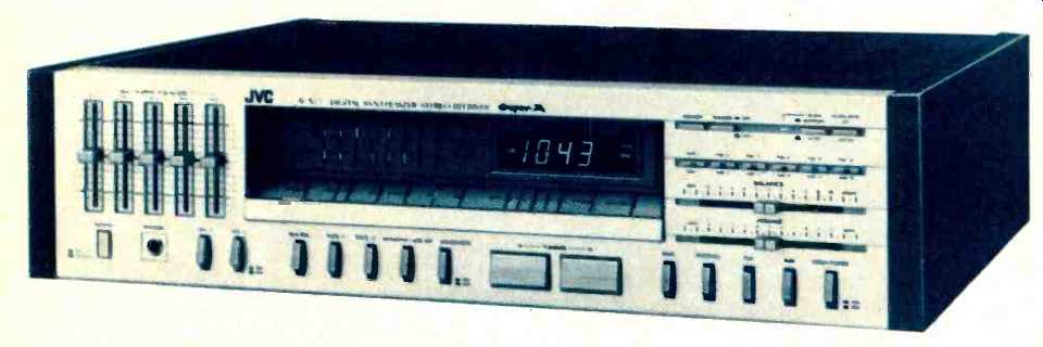
JVC has completely restyled their top receivers for 1980-81. The rather unusual cosmetic features introduced by the company three years ago have yielded to a more traditional looking faceplate having only one surface (the older receivers had controls mounted in two planes, both horizontally and vertically). There are still no rotary knobs on this receiver, and all control functions and switching functions are handled by slider-type potentiometers or touch-button switches.
Since the new R-S77 receiver features synthesized frequency tuning, there is no longer any need for a space-consuming, long dial scale. Instead, a small cutout area near the center of the panel is devoted to a digital display of frequency (for both AM and FM stations) at the right of the cutout, while at the left there are banks of LEDs which serve as power output indicators calibrated in watts referred to an 8-ohm load. Additional indicator lights below the digital-readout and power-indicating sections include a standby light (on so long as the unit is plugged into a live outlet, to indicate that station memories are retained), program source indicator lights for AUX, Phono, AM, and FM, and a series of LEDs which tell the user relative signal strength for both AM and FM received signals. A stereo indicator and an indicator which tells you when stations have been tuned in and "locked" are also present in this area of the panel.
Below the cutout area are five tiny rocker switches and a large pair of touch-switches for tuning "up" or "down" in frequency, either in a scanning mode (where tuning stops when usable signals are encountered) or manually in 200-kHz increments for FM and 10-kHz (or 9-kHz) increments for AM. The smaller switches in this area include an S.E.A. record switch (enabling the user to add graphic equalization to the signal prior to its emergence at the tape-out jacks), two tape monitor switches, a mono/stereo switch which also defeats muting on FM when in the mono position, and a loudness compensation switch.
At the left end of the front panel are five slider controls which constitute a graphic equalizer system that JVC continues to call their S.E.A. system. Center frequencies are about two octaves apart so that, in effect, the user has separate control of low bass, upper bass, mid-frequencies, lower treble and upper treble--a far more flexible system than could be had with ordinary bass and treble controls found on most receivers. The power switch, two separate speaker selector switches, and the usual headphone jack are also located in this area of the panel.
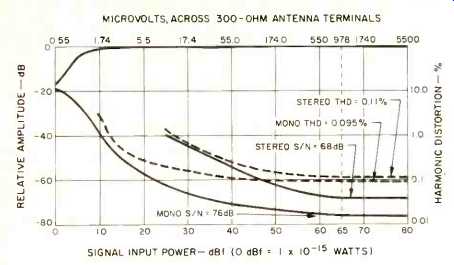
Fig. 1--Mono and stereo quieting and distortion characteristics, FM section.
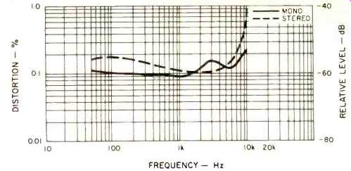
Fig. 2--Distortion vs. frequency, FM section.
At the right end of the pane) we find the program source selectors, a high-cut filter switch, slider controls for volume and balance (the latter with a detent-stop at its center point), six numbered buttons for storing or recalling that many AM plus that many FM frequencies, a "memory" switch (used when entering a frequency into one of the memory positions), a dimmer switch which dims display lighting, a scanning indicator to tell you when the tuner is scanning, a manual/auto switch that determines the manner in which the "up" and "down" tuning switches are to operate, and a lo cal/DX switch that determines the signal strengths at which automatic scanning will "lock" onto received signals. In general, the layout of this panel is well thought out, and if you review the features just discussed you cannot help but ad mire the way in which JVC's design engineers have been able to cram this many features and controls onto a panel that is not much more than four inches in height. The only repositioning of a control that we might have favored would be the movement of the auto-manual tuning switch closer to the "up" and "down" tuning buttons to which it is related.
The rear panel includes the usual 75-ohm coaxial, 300-ohm and external AM screw-type antenna terminals, a pivotable ferrite AM bar antenna, the necessary input and tape output jacks (plus a multi-pin DIN connector for tape deck connection of those decks which utilize such DIN cables), and two sets of color-coded speaker terminals of the screw/clamp type. An unusual feature also found on the rear panel (and the first time we have seen it on either a tuner or receiver) is a 9-kHz/10-kHz switch. Many areas of the world employ 9-kHz spacing between adjacent AM channels. Only the region consisting of North, Central and South America continues to employ 10-kHz spacing, and this may change in the near future to conform with the rest of the world. If that should occur, the purchaser of this JVC receiver will be able to simply flick a switch to obtain the new 9-kHz increments of tuning with frequency synthesis.
Circuit Innovations
As far as we know, this is the first time that JVC has employed their "Super A" amplifier circuitry in a receiver. For readers unfamiliar with this circuit approach, we should mention that Super A is a two-part solution to problems which JVC considers to be of importance in amplifiers. One circuit refinement takes care of nonlinearities which frequently occur in driver- and voltage-amplifier stages of a power amplifier, while the second circuit is concerned with the output stages of the amplifier and the prevention of "notch" or switching distortion. As explained by JVC, ordinary Class AB output stages actually operate in Class A over a limited range of low-output levels. When that range is exceeded, one of the complementary pair of output transistors is cut off because bias voltage in Class AB or Class B circuits is fixed. With each transistor of the pair cut off for part if not half of a cycle of the waveform being amplified, switching distortion can and often does result. Measured as a distortion percentage on a conventional distortion meter, such switching distortion seems almost insignificant, but in fact it is readily audible, particularly at lower listening levels where the amplitude of the distortion remains fixed while overall reference signal levels decrease. The relatively low readings are simply a result of the short duty cycle (and higher order harmonics) of the switching distortion.
JVC's solution to the problem, as exemplified in this receiver, is called a logarithmic compression bias circuit. The output stage uses a pair of complementary output transistors, as in a Class AB amplifier, but the bias voltage is made to vary so that the minimum bias voltage needed to maintain Class A operation is present even when the power transistors approach cutoff. With this approach, high efficiency of Class B is retained, while excellent linearity is not sacrificed at any power level. As we were soon to learn during our measurements of the amplifier section, the Super A circuitry results in unmeasurable distortion levels even when these are measured using conventional static or continuous test signals.
FM Performance Measurements
In the past, frequency-synthesized tuner designs have tended to be excellent insofar as tuning accuracy and low distortion are concerned but have suffered somewhat from poor selectivity and signal-to-noise ratios compared with conventionally tuned circuits. Those trade-offs seem to be disappearing, as evidenced by the excellent sensitivity (9.8 dBf), selectivity (80 dB as claimed), and signal-to-noise ratio (76 dB in mono) measured for the tuner section of this receiver. Quieting and distortion (for 1-kHz modulating signals in mono and stereo) characteristics for mono and stereo are shown graphically in Fig. 1. The 50-dB quieting point in mono was attained with signal strengths of only 13.5 dBf (2.6 uV/300 ohms), while for stereo 50-dB quieting sensitivity measured 36.1 dBf, or 35 p V across 300 ohms.
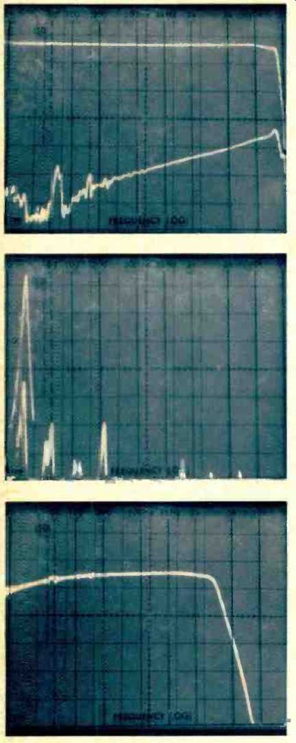
Fig. 3--Frequency response and stereo FM separation.
Fig. 4--Crosstalk and distortion products at 5 kHz, FM section.
Fig. 5-Frequency response, AM section.
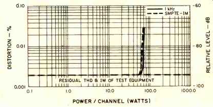
Fig. 6--At all but overload levels, THD and IM is lower than the residual
distortion of the test equipment.
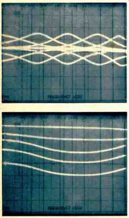
Fig. 7--Range of adjustment in the 5-band S.E.A. equalizer.
Fig. 8--Action of the loudness control.
Distortion was 0.09 percent in mono and 0.11 percent in stereo for a 1-kHz signal at a signal strength of 65 dBf. In fact, with somewhat stronger signals, THD in stereo actually de creased somewhat further. Figure 2 shows harmonic distortion levels for both mono and stereo plotted against frequency of the modulating signal, and aside from the rather high reading observed at 10 kHz in stereo, which was caused more by slight "beats" than by actual harmonic distortion, we see that THD levels remain consistently low for all musical fundamental frequencies of broadcast program material.
Figure 3 is a spectrum analyzer plot of frequency response of the tuner section in the stereo receiving mode (upper trace) as well as stereo separation (lower trace). Frequency o sweep is from 20 Hz to 20 kHz and vertical sensitivity of the display is 10 dB per division. At the specific test frequencies of 100 Hz. 1 kHz and 10 kHz, we measured separation figures of 53 dB, 51 dB and 33 dB. To separate crosstalk from distortion products in an unmodulated channel's output, we used our spectrum analyzer to display a reference 5-kHz signal in Fig. 4 (tall spike at left). Sweep range is now linear, from 0 kHz to 50 kHz, or 5 kHz per division. The shorter spike contained within the reference spike shows that separation at 5 kHz was actually close to 40 dB, while to the right we see some harmonic distortion components at 10 and 15 kHz as well as the expected 19-kHz and 38-kHz residual output products and sidebands which are above and below the 38-kHz carrier by a spacing of 5 kHz.
Capture ratio measured 1.0 dB as claimed, while selectivity was actually a bit higher than the 80 dB claimed, with readings of 82 dB at one end of the band and 81 dB at the other.
I.f. rejection measured in excess of 100 dB, while image rejection measured 80 dB. Spurious suppression measured 93 dB.
The frequency response of the AM tuner section of this receiver was better than most, as can be seen in Fig. 5. The-6 dB points occurred at 4 kHz and all the way down at 25 Hz, and while these numbers may not impress the high-fidelity oriented audio enthusiast, they are considerably better than those observed for most stereo receivers.
Amplifier Measurements
The power amplifier section of the JVC R-S77 receiver produced 72 watts of power per channel at 1 kHz into 8-ohm loads and 69 watts per channel at the frequency extremes of 20 Hz and 20 kHz. While power output into 4-ohm loads was considerably higher than the 60-watt rating (as high as 85 watts per channel at mid-frequencies), JVC would not be able to rate the amplifier any higher than 65 watts for the 4-ohm rating because of FTC preconditioning requirements. In fact, JVC provides no 4-ohm rating for this receiver.
As for distortion levels below rated power output, there is little we can discuss. As you can gather from Fig. 6, both harmonic and distortion readings are limited by the residual distortion of our test signals (around 0.002 percent) so we can only report that at all levels below overload, THD and IM for the Super-A designed amplifier are "less than 0.002 percent." Dynamic headroom, or the ability of the amplifier to deliver higher power levels on a short-term basis before clipping, was 1.6 dB, and damping factor, measured at 50 Hz and referenced to 8-ohm loads, was 50. Power bandwidth extended from 15 Hz to 30 kHz for full power at rated THD.
Preamplifier and Control Section Measurements
Since JVC has not elected to report input sensitivities in accordance with the new IHF/EIA Measurement Standards (we wonder why, inasmuch as they have switched over to reporting S/N ratios per the new IHF input and output reference levels), readers wishing to compare our measured input sensitivity results with those claimed by JVC will have to multiply our results by a factor of 17.78 dB, or by 7.75. We measured a phono sensitivity of 0.29 millivolt for 1-watt output, while in the high-level inputs, sensitivity was 21 mV for the same 1 watt of output. Signal-to-noise ratio in phono, referred to 1-watt output and using an input level of 5 mV, was 78 dB as against JVC's claim of only 75 dB and, for high-level inputs (referenced again to 1-watt output but with an input level of 0.5 volt), we measured 80 dB, A weighted, again better than claimed by JVC.
Overall frequency response was flat within 1 dB from 10 Hz to 50 kHz via the high-level inputs, and RIAA equalization accuracy was virtually perfect from 100 Hz upward to 20 kHz but had a positive rising characteristic reaching +1.0 dB at 30 Hz. Phono overload was 220 millivolts as against 180 mV claimed by the manufacturer.
The flexibility and versatility of the five graphic equalizer controls are best understood by examining the composite sweep 'scope photo of Fig. 7, in which you can see the maximum range of boost and cut offered by each of the five slider controls. Clearly, this sort of five-control arrangement provides a great deal more in the way of tone control flexibility than either two- or three-way tone controls.
Loudness compensation characteristics at various settings of the master volume control (approximately 10 dB apart) are plotted in the spectrum analyzer 'scope photo of Fig. 8 and are typical of what one usually finds in these simple loudness control switching arrangements.
Use and Listening Tests
The JVC Model R-S77 receiver delivered sound quality that can only be described as well balanced and uncolored. Controls were easy to use and did exactly what they were intended to do. We would have been more pleased with the control layout if JVC had supplied a subsonic filter instead of the high-cut filter. The action of the latter could be easily duplicated by the top control of the graphic equalizer, while the ultra-low frequency response capability of the amplifier section makes a subsonic filter an often-used and often-needed circuit, especially if warped records and less-than-perfect turntable systems are used in conjunction with the receiver.
Sound quality was good, too, using the radio facilities of the receiver, and we were especially conscious of the low-distortion reception obtainable with this frequency-synthesized tuner despite its excellent and relatively high alternate channel selectivity. The station memory feature is a nice addition (up to six AM stations plus six FM stations can be "memorized"), providing you remember (or write down) where you have placed which station (is it in memory number 3 or number 5?).
Sixty watts per channel seems to be an optimum value for most of the medium to higher efficiency speaker systems being offered these days and should not restrict listeners to "less than lifelike" sound levels in most medium-sized listening rooms. Abandonment of the "power race" by leading manufacturers such as JVC in favor of more audibly beneficial features and circuits was a wise course, in our opinion, and has made possible such cost-efficient products as this new receiver.
-Leonard Feldman
(Audio magazine, Jan. 1981)
Also see: Link |
JVC R-X500B Receiver (Equip. Profile, Dec. 1984)
JVC R-X80 Receiver (Nov. 1983)
JVC RX-9V A/V Receiver (Mar. 1987)
JVC S-300 FM Stereo/AM Receiver (Sept. 1976)
JVC Model A-X9 Stereo Integrated Amplifier (Jul. 1980)
= = = =