Manufacturer's Specifications:
FM Tuner Section:
Usable Sensitivity: Mono, 10.3 dBf.
50-dB Quieting Sensitivity: Mono, 14.8 dBf: stereo, 38.3 dBf.
S/N Ratio: Mono, 84 dB; stereo, 78 dB.
THD: Mono, 0.08% at 1 kHz; stereo, 0.08% at 1 kHz.
Frequency Response: 30 Hz to 15 kHz, + 0.5, -0.8 dB.
Capture Ratio: 1.5 dB.
Alternate-Channel Selectivity: 70 dB.
Image Rejection: 90 dB.
I.f. Rejection: 100 dB.
Stereo Separation: 50 dB at 1 kHz.
AM Tuner Section:
Sensitivity: External antenna, 30 ILV; internal antenna, 250 µV/m.
S/N Ratio: 50 dB.
THD: 0.5%.
Selectivity: 38 dB.
Image Rejection: 40 dB:
If. Rejection: 65 dB.
Video Section:
Output Signal Level: VCR out, 1 V peak to peak at 1-V peak-to-peak input.
Impedance: 75 ohms.
Synchronization: Negative.
S/N Ratio: 45 dB.
Crosstalk: 45 dB at 3.58 MHz.
Amplifier Section:
Power Output: 120 watts continuous per channel, 20 Hz to 20 kHz, both channels driven into 8-ohm loads.
Rated THD: 0.007%.
SMPTE IM: 0.007%.
Damping Factor: 45 at 8 ohms. 1 kHz.
Input Sensitivity for Rated Output: MM phono, 2.5 mV; MC phono, 250 mV: high level. 230 mV.
Recording Output Level: 230 mV.
Frequency Response: Phono, RIAA ±0.5 dB, 20 Hz to 20 kHz; high level, 5 Hz to 50 kHz, +0,-1.0 dB.
S/N Ratio: MM phono, 80 dB; high level, 77 dB.
Equalizer Center Frequencies:
63 Hz, 160 Hz, 400 Hz, 1 kHz, 2.5 kHz, 6.3 kHz, and 16 kHz.
Equalizer Control Range: ± 10 dB.
General Specifications
Power Consumption: 120 V, 60 Hz, 410 watts (510 VA).
Dimensions: 17 1/8 in. W x 5 in. H x 15 in. D (43.5 cm x 12.65 cm x 38.1 cm).
Weight: 23 lbs. (10.4 kg).
Price: $720.00
Company Address: 41 Slater Dr., Elmwood Park, N.J. 07407.
I'm beginning to wonder whether the race to integrate audio and video components into comprehensive home-entertainment systems isn't leading to designs that are altogether too complicated for the average music lover to operate. When you take your first look at JVC's newest and most powerful (120 watts per channel) audio/video receiver, you'll probably wonder how its designers managed to cram so many features into a single, relatively compact unit.
The RX-9V receiver is intended to serve as a master control center for a variety of audio and video components.
You can connect a turntable, a Compact Disc player, and a cassette deck. The audio and video tracks of a VCR or a videodisc player can also be fed to this unit, and its audio and video outputs can be connected to a TV monitor as well as to the recording inputs on a VCR. Two sets of speakers can be connected to the receiver, and either or both sets can be switched on, as desired. If you subscribe to cable TV, you can connect your cable to one of the antenna inputs on the back of the receiver while the other antenna input accommodates your regular FM antenna. Alternatively, since front-panel switching between antennas is possible, you can connect two FM antennas to the system, each oriented in a different direction.
The supplied remote allows you to control most of the RX 9V's functions from the comfort of your listening/viewing if your system includes certain other compatible JVC components (such as some of their CD players, cassette decks, and turntables), you can turn on and control their functions with this remote, which the company has dubbed the CompuLink remote-control system.
The operating features of the receiver itself are mind-boggling, to say the least. The RX-9V is equipped with a seven-band graphic equalizer rather than with simple bass and treble tone controls. Not only can you store five of your preferred response settings in the receiver's memory, but you can also select five factory-preset response curves.
These five preset curves have been created and permanently stored for such material as rock music, music with vocals, background music, movie soundtracks, and vocal-only programs. At the touch of a switch, the bar-graph-like indications used to set response curves are transformed into a real-time spectrum analyzer which lets you see the tonal or spectral content of the music to which you are listening.
Built-in microprocessor circuits, in addition to providing the functions you would expect, perform certain "judgmental" tasks as well. For example, if FM stereo reception is too weak or noisy, a circuit called QSC (Quieting Slope Control) is activated, reducing background FM noise at the expense of some stereo separation. Many tuner sections allow you to preset your favorite stations for instant recall, but the JVC tuner section goes farther. It can be told to scan for stations whose signal strength is adequate and then store the frequencies of those stations. (You determine what signal strength is adequate by dialing in a dB figure.) If the tuner stops at a station you'd rather not store, you can bypass that signal. Up to 16 station presets can be programmed in this manner.
Among its other audio signal-processing circuits, the RX 9V has an "acoustic expander" circuit; this simulates stereo spread for mono signals and tends to increase apparent separation when you are listening to stereo program material. A loudness-compensation control is also available for use during low-levee listening.
Control Layout
As was true of earlier JVC receivers, there is not a single rotary knob (or any other kind of knob, for that matter) protruding from the sleek, highly graphic front panel. All operating controls are pushbuttons. Three major illuminated, colored display areas occupy much of the front panel's upper section. The first of these is devoted to the graphic equalizer and spectrum analyzer, which JVC continues to designate as an "SEA" (Sound Effects Amplifier) section.
Below this display are the various pushbuttons needed to alter overall response settings, and those needed to call up memorized response curves. To the left of this display are the power switch, speaker selector buttons, and the usual stereo phone jack.
The second, more centrally positioned display area provides a wealth of information concerning selected audio and video program sources, status of the two tape monitor circuits, volume and balance settings, and other audio functions. This area serves as sort of a flow-chart diagram for the various signals you have chosen to send along to the various outputs. Incidentally, it is possible to watch one video program while listening to a completely different audio source. This feature makes simulcast viewing and listening extremely convenient. Program selector buttons are found below this display.
The third display area is dedicated primarily to the tuner.
It shows tuned-to AM or FM frequencies, signal level, selected antenna input, signal strength in decibels, tuner preset number, and the "stop" level for the scanning/preset function described earlier. Tape monitor switches and various other audio control buttons are found below this display area. Farther to the right are buttons that control volume level, channel balance, and tuning. Numbered station-pre set buttons and other controls associated with the tuner section are also located at the panel's right.
At first glance, the fully lit front panel seems a bit intimidating and complex, but the owner's manual clears things up quickly. I found that after an hour or so of using the RX-9V, the logic of its layout became apparent. From then on, it was easy to use all of its facilities, either via the front panel or from the remote control.
On the rear panel, audio inputs and outputs are grouped together, as are video-component inputs and outputs. Two separate video inputs (along with their audio track inputs) are provided, in addition to input and output connections for a stereo VCR. A separate TV monitor can also be connected. In addition to the usual 75-ohm FM antenna connector, the AM antenna terminals, and the supplied AM loop antenna, there are 75-ohm coaxial connectors for an incoming cable-TV line and for making an r.f. output connection to a VCR. As I mentioned earlier, the second r.f. input can be used, alternatively, for connecting a second, differently oriented FM antenna.
A pair of convenience a.c. outlets, the usual spring-loaded speaker terminals, an AM channel-spacing switch (9 kHz for European use, 10 kHz for the U.S.), and terminals la belled "Synchro" (for use with other JVC components that have CompuLink circuitry) complete the rear-panel layout.
Tuner Measurements
Figure 1 shows how FM signal-to-noise ratio and distortion vary as a function of incoming signal levels at the antenna terminals. Usable sensitivity in mono measured 10.0 dBf, marginally better than claimed. Stereo usable sensitivity was a function of the stereo threshold and muting setting, which, in the sample I tested, was set at around 28 dBf. For 50-dB quieting, I measured a very low 13 dBf in mono and 37 dBf in stereo, both better than claimed. Best S/N ratios in both mono and stereo fell a bit short of JVC's specs but were still very respectable for a receiver of this type, measuring 82 and 76 dB, respectively. Harmonic distortion in mono FM for a 100%-modulated, 1-kHz signal was 0.08%, exactly as claimed, but in stereo the THD was a low 0.06%, as against the spec of 0.08%.
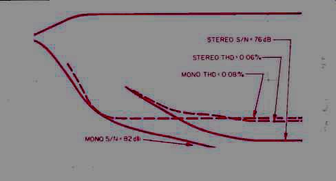
Fig. 1-Mono and stereo quieting and distortion characteristics, FM section.
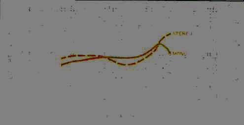
Fig. 2-THD vs. frequency. FM section.
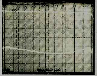
Fig. 3-FM frequency response (top trace) and separation vs. frequency (bottom
trace).
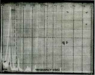
Fig. 4-Separation and crosstalk components for a 5-kHz FM modulating signal.
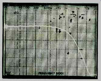
Fig. 5-AM frequency response.
Figure 2 shows how FM THD varied with modulating frequencies. At 100 Hz, THD was 0.07% in mono and 0.09% in stereo; at 6 kHz (the other test frequency established by the EIA's Standard), THD was 0.18% in mono and 0.20% in stereo. These results compare favorably with those obtained for some of the best separate tuners I have measured.
Figure 3 is a spectrum-analyzer plot of FM frequency response and stereo separation. Response was flat from 30 Hz to 15 kHz, with maximum deviation from perfectly uniform response reaching-0.4 dB at 30 Hz and-0.6 dB at 15 kHz. When you consider that this unit's 19-kHz rejection was nearly 70 dB, you can appreciate what a job it was to design an FM audio output circuit that remains nearly perfectly flat in response all the way up to 15 kHz. All but a very few tuners I have measured exhibit a loss in response of anywhere from 1.0 to 3.0 dB at this frequency. Stereo separation, the lower trace in Fig. 3, was excellent. At the three required test frequencies of 100 Hz, 1 kHz, and 10 kHz, stereo separation measured 45, 52, and 41 dB, respectively. Figure 4 compares the output from a channel 100% modulated by a 5-kHz signal (tall spike at left of the 'scope photo) to that of the unmodulated opposite channel (shorter spike within the tall one). The few spurious components farther to the right in the photo represent crosstalk at the unmodulated channel's output, and consist primarily of harmonic distortion and very low-amplitude 19- and 38-kHz components. The horizontal sweep in Fig. 4 is linear and extends from 0 Hz to 50 kHz, and the vertical scale is 10 dB per division.
Capture ratio measured 1.5 dB, using a 45-dBf signal as a reference. Alternate-channel selectivity was 72 dB. Image, i.f., and SCA rejection measured 90 dB, greater than 100 dB, and 65 dB, respectively. Muting level was the same as stereo threshold, 28 dBf. To receive signals less powerful than that, you must press the button which simultaneously defeats the muting and puts the tuner into mono mode. The reasoning here is that you wouldn't want stereo at such low signal levels because of the added background noise. Incidentally, while it was difficult to "push" the tuner into its special Quieting Slope Control mode deliberately, the tuner did go into this mode when I used generated test signals during some of my listening tests. I was able to detect a decrease in separation and an attendant decrease in back ground noise when the QSC feature was active.
Figure 5 is a plot of frequency response for the RX-9V's AM tuner section. The sweep in this 'scope photo is logarithmic and extends from 20 Hz to 20 kHz. As you can see, response is about as disappointing as it is in the AM circuits of most high-fidelity tuners and receivers. The-6 dB point was reached at a frequency of about 2.8 kHz.
Amplifier Measurements
The power-amplifier section delivered its claimed 12d watts per channel of continuous power at its rated distortion of 0.007% at mid-frequencies. At the frequency extremes, however, THD rose a bit beyond the rated level, to 0.009% at 20 Hz and 0.015% at 20 kHz. Figure 6 is a "three dimensional" plot of THD versus frequency and power output into an 8-ohm load. While the levels of THD are hardly worth getting upset about, JVC might well consider being a little more conservative in their published THD rating, lest they arouse the ire of the FTC.
What proved disappointing was the amplifier section's performance when driving 4-ohm loads. The receiver's current-limited power supply was able to deliver a maximum of only 80 watts per channel; at that, THD was considerably higher than it was for this power level when driving 8-ohm loads. At 50 watts per channel into a 4-ohm load, THD at mid-frequencies was back to its low levels of around 0.007% to 0.009%. It is not surprising, in view of the performance at lower output impedances, that JVC chose not to provide a standard 4-ohm power rating for this receiver.
Damping factor, measured with a test frequency of 50 Hz and referred to 8-ohm loads, was 71.5. Dynamic headroom was a moderate 1.0 dB, again with 8-ohm loads.
One of the most outstanding features of the RX-9V's preamplifier/control section is its seven-band equalizer/analyzer. The five factory-assigned response curves in the graphic equalizer's memory circuits are very much suited to their suggested applications. But if you don't like those curves, you can create your own and assign them to additional memory locations for future use. Figure 7 shows the maximum boost and cut range of each of the seven equalizer bands. If you are against tone controls of any sort, it's equally easy to bypass the whole arrangement and restore totally flat response at the touch of a button. Figure 8 shows the typical bass and treble compensation afforded by the loudness-control circuit incorporated in the RX-9V.
Input sensitivity for the moving-magnet phono section, referred to 1 watt output, measured 0.24 mV. For the moving-coil inputs, 0.02 mV was required at the input terminal to produce 1 watt of output at 1 kHz. Frequency response for the phono section was accurate to within + 0.6 and-0.4 dB of the RIAA playback curve from 20 Hz to 15 kHz. Phono overload at the MM inputs occurred with a 1-kHz signal of 100-mV amplitude; 'or the MC inputs, overload was 20 mV.
Input sensitivity for the high-level inputs measured 22 mV for 1 watt output. Frequency response for the high-level inputs (both audio-only and video-related) was flat within 1.0 dB from 8 Hz to 40 kHz and within 3 dB from 4 Hz to 75 kHz.
Signal-to-noise ratio for the MM phono inputs, referred to 1 watt output and with 5 mV of a 1-kHz signal applied to the inputs, measured an impressively high 83 dB (as against 80 dB claimed). For the MC inputs, using a 0.5-mV input and adjusting the volume control to produce a 1-watt output into 8-ohm loads, S/N was 70 dB. For the high-level inputs, again referred to 1 watt output but with a 0.5-V signal applied, S/N measured 80 dB, while at minimum volume settings, S/N measured 87 dB below 1 watt output. Translated to rated output, this would be an S/N ratio of greater than 107 dB.
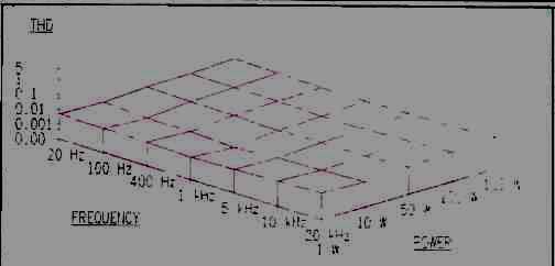
Fig. 6-THD vs. frequency for five power levels with an 8-ohm load.
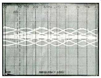
Fig. 7-Equalizer control range.
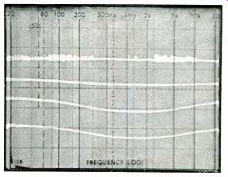
Fig. 8--Loudness-control characteristics at various volume settings.
Use and Listening Tests
Even though this receiver didn't deliver as much power as I would have expected at 4 ohms, I was pleased to find that it was able to drive my reference speakers (which look more like 4 ohms than like 8 at most frequencies) to lifelike sound levels and even a bit beyond. The FM tuner performance was excellent. As I mentioned earlier, on the few weak stereo signals that were nevertheless strong enough to overcome the muting/stereo threshold, the QSC circuit worked well, retaining adequate stereo separation while at the same time reducing background noise and distortion significantly. I have the feeling that this circuit is more than just a simple "blend" type, since it seemed to counter the effects of multipath more than I would have expected from such a circuit. However, since I wasn't given a schematic of the RX-9V and since relatively little detail concerning this circuit is provided in the owner's manual, I'm only guessing about that.
I found the front-panel displays to be extremely helpful in sorting out the many options and signal flow paths that are available. While I like to think of myself as an independent spirit when it comes to tone-control settings, I must confess that I called up the equalizer's preset response curves more than once during my listening tests. They really do help with certain kinds of music. At other times I couldn't help but switch the display to its alternate function of real-time spectrum analyzer. When I think of how much I spent for a seven-band spectrum analyzer-in the form of a portable test instrument-some years ago, I am amazed that JVC was able to incorporate such a feature in a receiver that sells for less than my test instrument originally cost.
Audio signals, including phono and CD, were in no way degraded by passing through this receiver. Video signals were also handled with what seemed to me to be little or no degradation. In that respect, however, this unit acts only as a sort of control center or switchboard, unlike some other A/V receivers now available that allow you to do some video-signal processing as well.
Especially in view of the rising value of the Japanese yen, at its suggested retail price of $720, the JVC RX-9V is a remarkably designed and executed product. If you're planning to assemble an integrated audio/video system or simply to add some video components to your current stereo system, I can't think of a more appropriate unifying product to serve as such a system's central element.
-Leonard Feldman
(Audio magazine, Mar. 1987)
Also see:
JVC R-X80 Receiver (Nov. 1983)
JVC S-300 FM Stereo/AM Receiver (Sept. 1976)
JVC Model KD-85 Stereo Cassette Deck (Nov. 1978)
KLH Model Fifty-Two Stereo Receiver (Aug. 1973)
= = = =