Manufacturer's Specifications
FM Tuner Section
Usable Sensitivity: Mono, 10.8 dBf.
50-dB Quieting Sensitivity: Mono, 16.2 dBf; stereo, 37.7 dBf.
S/N Ratio: Mono, 88 dB (at 80 dBf); stereo, 82 dB (at 80 dBf).
THD at 65 dBf: Wide, 0.02% at 1 kHz, 0.04% at 100 Hz, and 0.07% at 6 kHz in mono; 0.04% at 1 kHz, 0.08% at 100 Hz, and 0.08% at 6 kHz in stereo.
Narrow, 0.15% at 1 kHz in mono and 0.5% at 1 kHz in stereo.
Capture Ratio: Wide, 1.0 dB.
Alternate-Channel Selectivity: Narrow, 85 dB.
Stereo Separation: Wide, 60 dB at 1 kHz and 45 dB from 30 Hz to 15 kHz.
Frequency Response: 20 Hz to 15 kHz, +0, -1 dB.
Auto Tuning Level: 29.3 dBf.
AM Tuner Section
Sensitivity: 220 µV/meter; external antenna, 10 V.
Selectivity: 60 dB. S/N Ratio: 50 dB.
Video/VHF Section Input Sensitivity and Impedance: 1V p-p, 75 ohms unbalanced.
Output Level and Impedance: 1 V p-p, 75 ohms unbalanced.
R.f. (VHF) Input and Output Impedance: 75 ohms unbalanced.
Amp and Preamp Sections
Power Output: 125 watts per channel, 20 Hz to 20 kHz, 8-ohm loads.
THD: 0.005%.
Input Sensitivity (For Rated Output): MM phono, 2.5 mV; MC phono, 0.25 mV; high-level inputs, 150 mV; power amp input (at preamp/ main terminals), 1.0 V.
Phono Overload: MM, 150 mV; MC, 14 mV.
Frequency Response: Phono (RIAA equalization), 20 Hz to 20 kHz, ±0.3 dB; high level, 5 Hz to 100 kHz, +0,-3.0 dB.
Tone Control Range: Bass, ±8 dB at 100 Hz; treble, ±8 dB at 10 kHz.
Subsonic Filter: 6 dB per octave, 20-Hz cutoff.
Muting: -20 dB.
Loudness Contour (Volume at-40 dB): +6 dB at 100 Hz; +3 dB at 10 kHz.
S/N Ratio (A-Weighted): MM phono, 86 dB; MC phono, 67 dB; high level, 100 dB.
General Specifications
Power Requirements: 120 V, 60 Hz, 360 watts.
Dimensions: 16-9/16 in. (42 cm) W x 5 3/8 in. (15 cm) H x 17-3/16 in. (43.7 cm) D.
Net Weight: 33 lbs., 1 oz. (15 kg).
Price: $799.95.
Company Address: P.O. Box 1720, Long Beach, Cal. 90801.
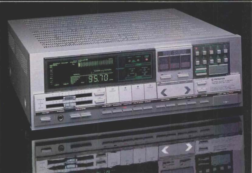
If you had any doubts about the so-called "marriage" of audio and video, all you have to do is take a look at (and a listen to) Pioneer's top receiver. In addition to offering just about every imaginable feature you would expect to find in a full-featured, high-powered AM/FM stereo receiver, the SXV90 can serve as the central control unit for such video components as a VCR, a videodisc player, and even a video game or personal computer. Recognizing that not all video program sources offer stereo sound channels or high signal-to-noise ratios, the SX-V90 incorporates a stereo simulation circuit, plus Dynamic Noise Reduction (DNR), to help reduce such noise as the tape hiss on conventional VCR audio tracks.
While incorporating many switching and control features that will appeal to the video enthusiast, Pioneer has not overlooked the important basics of AM/FM tuner, preamplifier and power amplifier design. The amplifier section incorporates Pioneer's "non-switching" circuitry, a high-speed servo system that automatically adjusts bias current at the power stages to suit input-level requirements. The output devices are never allowed to be switched off entirely, so the system delivers Class-A performance with the efficiency of a Class-B amplifier design.
Quartz PLL digitally synthesized tuning is incorporated in the tuner section, and as many as 10 AM and 10 FM stations can be preset for instant recall. Alternatively, you can tune up and down the dial and have the tuner lock onto acceptable signals automatically, or you can tune manually. When you preset an FM station, you can also preset its i.f. bandwidth (wide or narrow), so each time you call up that station, the tuner's bandwidth will be set accordingly. The microprocessor also allows you to preset two favorite listening levels (e.g., for day and late-night listening). It also lets you preset sensitivity individually for each input, to compensate for differences in output levels between program sources so it won't be necessary to readjust the volume when switching between them.
As for the video facilities, the SX-V90 provides three separate sets of inputs (video, stereo audio and r.f.) and two sets of outputs (one video and audio, the other video and r.f.) for video equipment, even allowing simultaneous video feed to a TV monitor and r.f. feed to an ordinary TV set. This input/output flexibility is matched by front-panel switching facilities so versatile that you can even dub videotapes from disc or a second VCR while listening to any audio source.
Control Layout
The most striking thing about the front panel is the total absence of protruding rotary controls. The many functions of the receiver are all handled by light-touch buttons or, in the case of the tone controls, by horizontal sliders. The power switch is located at the lower left of the panel.
Alongside are a stereo headphone jack and two speaker selector pushbuttons. Just above these controls are the aforementioned, sliding tone controls, and to their right are "Tape 1" and "Tape 2" monitor switches. Large, nearly square touch pads to the right of the monitor switches are used to select "CD/AUX," "A V1," "FM" or "Phono" inputs.
Below these large selector buttons are five smaller pushbuttons which are used for tape-to-tape dubbing, subsonic filter activation, connection of any kind of adaptor or decoder that needs to be incorporated into the audio signal path (e.g., equalizer, time-delay unit, or decoder), wide/narrow FM i.f. selection, and moving-coil/moving-magnet phono cartridge selection.
A multi-purpose display occupies nearly half of the upper portion of the front panel. I found some of the bright green displays a bit garish (there's no way to turn them off), though I suspect many users will appreciate the vas: amount of information presented. Output power is displayed as a sort of geyser-like green fountain which increases in height as power output increases, with separate indications provided for left and right channels. Volume settings are shown by a calibrated scale having 22 increments, and this same horizontal green scale is used for indicating charnel-balance setting. A signal-strength meter also appears as a green display, with the AM or FM frequency indications to its right.
(The FM frequencies are displayed to two decimal places.) Other illuminated indicators tell you which preset volume level you've selected, whether loudness or audio muting functions are engaged, whether you are in the manual or auto tuning modes, which speaker systems ("A" or "B") have been selected, and whether or not an FM broadcast is being received in stereo. The rightmost section of this large display area tells you which of the several video and audio program sources has been selected and which, if any, of the tape monitor circuits is active. All in all, there's not much that can take place within the SX-V90 that won't be shown by one of the many elements of this elaborate display.
To the display's right are three large touch pads that select video input sources. Below these are smaller keys that turn on the "DNR" noise-reduction circuitry and the "Simulated Stereo" circuit. A large rocker pad adjusts volume level; two volume levels may be preset (when used with the "Memory" button) and selected with the "A" and "B" buttons just to the volume rocker's right. Separate "L" and "R" buttons are used to alter channel balance. When both are touched at the same time, balance is returned to its electrical "center" (equal signal levels to both channels). To the right of the balance pushbuttons are the "Loudness," stereo/mono, and "Mining" switches.
The upper-right comer of the panel is devoted to the tuning options. "Auto/Manual" and "Memory" switches are positioned to the left of a large "Down/Up" rocker switch; above these are 10 small "Station Call" keys and indicators which select previously memorized AM or FM stations.
The last little surprise offered by the front panel of this versatile receiver is to be found behind a little removable panel at the lower right corner. When this cap is removed, "Video Disc Output" jacks are visible. These enable you to copy the contents of a videodisc (or any other audio/video source connected to the rear-panel "Video Disc" inputs) onto a VCR. This can be done even when the receiver is switched off, as the jacks simply provide a convenient passive connection to the rear-panel disc inputs.
The rear panel of the SX-V90 has a full set of jacks for both audio and audio/video program sources. On the audio side are the "Phono" and "CD/AUX" inputs, plus input and output jacks for two tape decks and an "Adaptor"; there are "Pre Amp Out" and "Power Amp In" jacks, too, connected by external jumpers.
On the video side, things get more interesting. The three video inputs ("VCR 2/Game/Computer," "VCR 1/(TV Ant)," and "Video Disc") are equipped to take either VHF-channel r.f. signals (via standard F-connectors) or video plus stereo audio; the two "VCR" inputs also have "Stereo/Mono" switches, with the left-channel audio jack designated for mono use.
The main "Output" provides both a VHF r.f. feed to a conventional TV set and a composite video feed to a TV monitor, both of which can apparently be used at once. The audio signal corresponding to this video output would go through the receiver's speaker and tape output jacks. Another set of output jacks provides video and stereo audio signals from whatever is hooked to the "VCR 1" input; confusingly, though marked "For Copy (From VCR 1)," it is grouped with the "VCR 2" inputs.
The audio/video and r.f. circuits are apparently switched in parallel. The SX-V90 does not demodulate r.f. signals into audio and video-or do the reverse. So, if your output screen is an ordinary TV, you'll have to take r.f. signals from your VCRs, videodisc player, computer or game in order to feed it; if your screen is a monitor, without a tuner, you'll have to use the audio and video connections. You'd probably do this in any case, but it does open up interesting possibilities for tricky, simultaneous switching of two different A/V systems, one using r.f. and the other audio/video signals.
There are also r.f. connections for the audio side, of course: 75- and 300-ohm connections for FM and, above them, a jack for possible connection to a future AM stereo decoder. An external AM antenna terminal is near the left end, of the rear panel, and an accessory AM loop antenna, which can be remotely mounted from the receiver, is supplied with the SX-V90.
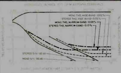
Fig. 1--Mono and stereo quieting and distortion characteristics, FM section.
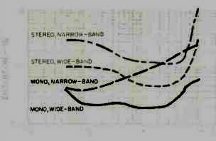
Fig. 2--THD vs. modulating frequency, FM tuner section.
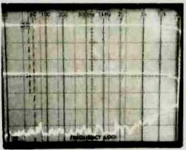
Fig. 3--Freq. response (upper trace) and separation (narrow i f. position,
center trace; wide i.f. setting, bottom), FM section.
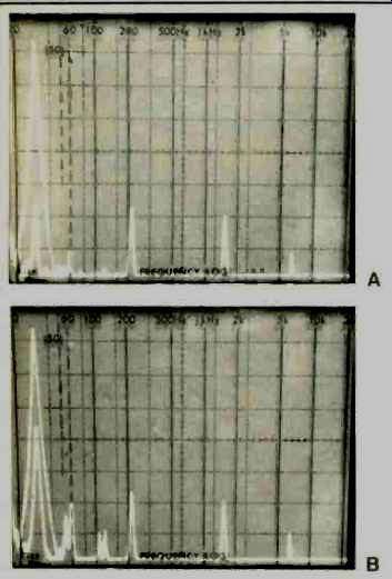
Fig. 4--Analysis of 5-kHz distortion and crosstalk in wide-band i.f. mode
(A) and in narrow-band i.f. mode (B).
Two switches near the antenna terminals adapt the receiver's tuner section to the broadcast standards of different countries. A slide switch near the antenna terminals selects the incremental tuning steps of the frequency-synthesized tuning system. You can choose 9- or 10-kHz steps for AM (9-kHz steps are used in many parts of the world other than the U.S.) and 50- or 100-kHz tuning steps for FM. This is an extremely useful feature not only because you may want to use the receiver in a foreign country, but also because some cable TV companies that provide FM stereo service do not always position FM stations at standard 100or 200 kHz increments on the dial. A 50/75-uS de-emphasis selector switch is positioned near the frequency-increment selector.
Speaker terminals for the two sets of speakers, as well as three a.c. convenience receptacles (one switched, two unswitched) are near the right end of the panel.
Tuner Measurements
Figure 1 shows signal-to-noise ratio and distortion as a function of input signal strength. While signal-to-noise remained essentially unchanged when I switched from the wide to the narrow i.f. mode, distortion increased significantly in the narrow i.f. mode, as might be expected. I measured an incredibly high 86 dB of signal-to-noise in mono. (I suspect that my test setup is not capable of measuring the full 88 dB claimed by Pioneer, so don't be too concerned about the slight discrepancy.) In stereo, S/N reached a maximum of 82 dB, as claimed. THD in mono, using the wide-band i.f. setting for a fully modulating 1-kHz signal, measured a very low 0.02%. I was impressed as much by this lower reading from the tuner section as I was by the ability of my generator to produce a signal that contained so little THD to begin with! Switching to the narrow i.f. mode, the THD was still comfortably low, with readings of 0.08%. In stereo, once again using the wide-band setting, THD for the 1-kHz test signal measured only 0.05%, but when I switched back to the narrow i.f. mode, the reading increased to 0.13%. Usable sensitivity in mono measured 10.8 dBf, as claimed; in stereo it was determined by the switchover function from mono to stereo, which occurred at around 28 dBf.
It took an input signal of 18 dBf to achieve 50-dB quieting in mono and 38 dBf of signal to achieve that quieting level in stereo. A plot of distortion versus modulating frequencies is shown in Fig. 2 for mono and stereo, for both the wide and the narrow i.f. settings of the front-panel bandwidth switch.
Even in the narrow i.f. position, THD at 6 kHz in stereo was only 0.14%. As might be expected, stereo separation suffers when the bandwidth switch is set to the narrow i.f. position. As shown in the spectrum analyzer 'scope photo of Fig. 3, however, separation remains amazingly constant over the entire audio spectrum, yielding an acceptable separation between channels of around 30 dB. With the bandwidth switch set to the wide i.f. position, mid- and low-frequency separation measured a very high 60 dB, decreasing to a bit less than 50 dB at 10 kHz.
Figures 4A and 4B illustrate what happens to crosstalk, separation and distortion components when operation of the receiver is switched from the wide-band to the narrow-band i.f. mode. In these 'scope photos, sweep is linear from 0 Hz to 50 kHz. The tall spike near the left edge of each photo is the desired 5-kHz output from the modulated channel. The shorter spike within the taller one is the 5-kHz component seen at the output of the unmodulated channel. Note how much smaller this undesired output is in Fig. 4A (wide-band mode) compared with its amplitude in Fig. 4B (narrow i.f. mode). Note, too, that while the 19and 38-kHz "spikes" (seen further to the right in each photo) remain essentially the same regardless of i.f. bandwidth, the second- and third-order distortion components of the 5-kHz modulating signal appearing in the unmodulated channel output (just to the right of the 5-kHz spikes) are much greater when the receiver is in the narrow i.f. mode than in the wide i.f. mode.
Capture ratio in the wide i.f. mode measured exactly 1.0 dB, as claimed. Alternate-channel selectivity measured 87 dB in the narrow mode but, as might be expected, decreased to 53 dB in the wide mode. It goes without saying that, if it is at all possible, the receiver should be operated in its wide i.f. mode. Only if you encounter interference from adjacent channels should the tuner be switched to the narrow i.f. mode, since separation is much poorer and distortion tends to increase. It is to Pioneer's credit that even when the SX-V90 is operated in the narrow mode, the distortion and separation figures remain good enough for most listening purposes.
Spurious rejection, image rejection, and i.f. rejection were all better than 90 dB. Overall FM frequency response was absolutely flat to 10 kHz and down only 1.0 dB at 15 kHz.
Stereo threshold, as noted earlier, occurs with an input signal level of 28 dBf. SCA rejection was better than 65 dB, while 19- and 38-kHz suppression was also on the order of 65 dB, referred to 100% modulation levels.
I didn't spend too much time measuring the performance of the AM tuner section, but I was happy to find that it exhibited a very flat frequency response characteristic all the way out to 4 kHz, as shown in the 'scope photo of Fig. 5.
Amplifier Measurements
The power amplifier section of this receiver delivered 144 watts per channel before clipping. Dynamic headroom was a modest 0.8 dB above the rated value of 125 watts per channel.
I had difficulty obtaining the ultra-low 0.005% THD readings claimed by Pioneer, but this may well have been a function of my test equipment. I note that Pioneer uses an audio spectrum analyzer to obtain their low readings, rather than a meter-equipped distortion analyzer. It may well be that my test setup was reading noise and other components that are not, strictly speaking, harmonic distortion. Whatever the reason, the best I could do was to get readings of 0.01% at rated output, and the measurements were about the same at 1 kHz, 20 Hz and 20 kHz. I would hardly fault the amplifier design, even if my results are accurate for this sample. A 0.005% THD specification is something of an exercise in engineering specsmanship and bears little relationship to how good the amplifier will sound, as all of us have come to learn over the years.
Damping factor for the power amplifier section measured 45. The CCIF-IM (twin-tone) distortion was a low 0.038% at rated output, while IHF IM measured almost as low, with a reading of 0.0513% for rated output.
Phono input sensitivity measured 0.2 mV (for 1-watt output) at the moving-magnet cartridge input; in MC position, sensitivity was 0.02 mV. A 12-mV signal at the high-level inputs produced 1 watt of output into 8-ohm loads. Phono overload for the MM phono input, using a 1-kHz test tone, was 175 mV, well above the 150 mV claimed. For the MC inputs, overload was 15 mV. Overall frequency response was flat within 1 dB from 11 Hz to 60 kHz and within 3 dB from 5 Hz to 100 kHz, exactly as claimed by Pioneer. The RIAA equalization was a bit off at both the low- and high frequency ends of the spectrum, deviating from the standard curve by a maximum of +0.2 dB at 50 Hz and +0.3 dB at 15 kHz. The range of the bass and treble tone controls is illustrated in the spectrum analyzer 'scope photo of Fig. 6.
Signal-to-noise ratio in phono, referred to a 5-mV input signal at the MM inputs and with the volume control adjusted for a 1-watt reference output signal, measured a very respectable 82 dB. An identical signal-to-noise reading was obtained for the high-level inputs, this time referred to a 0.5V input signal and a 1-watt output signal. Switching to the MC phono inputs, I obtained an S/N reading of 68 dB. All measurements were A-weighted. Residual noise with the volume control at minimum was 89 dB below 1-watt output.
Both the loudness control and the subsonic filter operated in the usual manner.
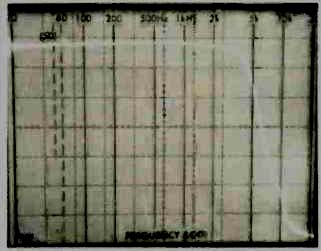
Fig. 5--Frequency response, AM section.
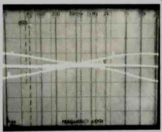
Fig. 6--Bass and treble control range.
Use and Listening Tests
I must confess that I spent perhaps too much of the time I assign to hands-on use of a product in exploring the SXV90's potential as a control center for audio and video equipment. I rather liked the idea of being able to hook my VCRs (a portable and a table-top model) and my laser videodisc player to one central component. Since I already have a TV monitor and a TV tuner/controller in my listening/ viewing room, I ran into some facilities duplication as I tried to integrate my audio and video systems. Still, the versatility of the SX-V90 receiver as a central component for handling video and audio program sources is awesome. Audio enthusiasts who are about to create their own audio/video entertainment center are sure to appreciate all of this receiver's switching and connection capabilities.
After I had my fill of connecting everything I own and trying out every switching combination made possible by the SX-V90, I settled down to some serious listening. I was particularly interested in the DNR and stereo-synthesizing circuits, since I had not as yet traded in my early mono VCRs for either VHS Hi-Fi or Beta Hi-Fi stereo. If any of you are in my situation (as far as VCR equipment is concerned), you know how noisy and hissy the soundtrack from videotape can be, and how dull and flat it can sound in the absence of stereo. Well, I have tried DNR before on other equipment, but I must say that it is particularly effective as incorporated by Pioneer in the video sections of this receiver. Some old videotapes (which I know to have no better than a 40-dB signal-to-noise ratio) sounded almost acceptable with the DNR circuitry operating. Of course, there are times when the musical content can trick the DNR somewhat, but after all, it is only a single-ended noise-reduction system. As such, it worked very well.
Even more interesting was the stereo synthesizer. I expected it to be another comb-filter type synthesizer that simply introduces a series of nulls and peaks into the response of each channel (never at the same point in left and right channels) to create a pseudo-stereo effect. Much to my surprise, when I measured the response of each channel with "Simulated Stereo" turned on, it was still perfectly flat; there were none of those peaks and valleys so characteristic of some stereo simulators. And, when listening to musical programming, the simulator did provide a pleasing, if moderate, stereo effect. I suspect that Pioneer is, in some controlled way, fooling around with phase, but I still haven't figured out exactly what they're doing. In any case, I didn't find it at all objectionable. With some types of programming it was downright pleasant! I have one minor criticism: The volume-control arrangement can cause problems. Suppose you leave it set, say, at a very loud level (because you were listening to an audio Program source that delivered a low signal voltage) and then turn the power off. When next you turn on the receiver, the volume level will be set at that same high level. This time you may have switched program sources to a CD player or even the self-contained tuner, both of which may provide greater signal voltages. After power-supply stability has been attained (a few seconds), you will be blasted with very loud sound. True, the indicators in the display show you that the volume control is set high, but you don't have enough time to correct it with the volume-control rocker switch, which alters volume rather gradually. The solution, of course, would be to lower the volume setting every time you are through listening to the receiver--but how many of us will remember to do that? So, what about the sound quality of this receiver? To that I can only say that it measured up to the best of them. There's enough power here to handle the wide dynamic range of new digital audio program sources with the ability to drive medium-efficiency speaker systems to adequate sound pressure levels. The FM tuner section is sensitive, and stereo FM reception was particularly clean and distortion free. Given its great sound, and its tremendous flexibility and versatility as an audio/video control center, one can hardly balk at the price of the SX-V90. Pioneer's design group must have spent a great deal of time coming up with this receiver, and, in my opinion, the time was well spent.
-Leonard Feldman
(Adapted from : Audio magazine, Jan. 1985 )
Also see:
Pioneer A-9 Integrated Amplifier (Dec. 1981)
Pioneer Model SX-1980 Stereo AM/FM Receiver (Equip. Profile, Sept. 1978)
Fisher RS-Z1 Receiver (Aug. 1990)
= = = =