Manufacturer's Specifications
Power Amplifier Section:
Power Output: 110 watts per channel, 8 ohms, 20 Hz to 20 kHz.
Rated THD: 0.003 percent.
SMPTE IM: 0 005 percent.
Damping Factor: 60.
Preamplifier and Control Sections:
Input Sensitivity for Rated Output: Phono MM/MC, 2.5/0.1 mV; high level, 150 mV.
Phono Overload, MM/MC: 250/10 mV.
Frequency Response: Phono RIAA, ±0.2 dB; high level, 5 Hz to 200 kHz, +0,-3 dB.
Tone Control Range: Bass, ±10 dB at 100 or 50 Hz, turnover frequencies at 400 and 200 Hz; treble, ±10 dB at 10 and 20 kHz, turnover frequencies at 2.5 and 5.0 kHz.
Subsonic Filter Cutoff: 20 Hz, 12 dB/ octave.
S/N, A Weighted, Re Rated Output: Phono MM/MC, 90/74 dB; high level, 110 dB.
Muting: -20 dB.
General Specifications:
Power Requirements: 120 V, 60 Hz, 350 watts.
Dimensions: 16-9/16 in. (42.07 cm) W x 5-15/16 in. (15.08 cm) H x 16 15/16 in. (43.02 cm) D.
Weight: 35 1/4 lb. (15.86 kg).
Price: $800.00.
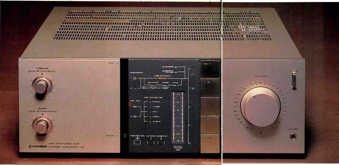
Besides its brand-new cosmetics (which represents a radical departure from their earlier components), there's a great deal that's new and different about Pioneer's top-of-the-line A-9 integrated amplifier. For one thing, the company has come up with its own dynamic bias system which they call a Non-Switching Amplifier system. Moreover, the power amplifier section as well as the equalizer amplifier are both equipped with a d.c. servo circuit which permits the elimination of all coupling capacitors in the signal path while maintaining drift-free d.c. stability. Other operational and circuit features will become apparent as we re view the layout of the front panel of this sleek-looking amp.
The front panel is divided into three sections. A large calibrated master volume control, -20 dB muting switch, stereo phone jack, and a vertical row of program selector touch-button switches are all located on the right-most third of the panel. The center third incorporates a series of light indicators and pictographs which clearly tell the user what source has been selected, which speakers have been chosen, and a large variety of other indications which leave no doubt in the listener's mind as to what is taking place and what signal routings or processing have been selected. A power circuit protection indicator, also located in this area, changes from green to red depending upon the operating mode of the protection circuitry.
At first glance, the left-most third of the panel seems devoted only to a power switch and bass and treble controls, but a slight pull along the top edge of this section causes a hinged door to swing down and reveal many other hidden switches and controls. There are, for example, a channel balance control and a record selector switch which not only permits dubbing from one connected deck to another but also lets you record from one program source while listening to a completely different pro gram. Another series of tiny push buttons selects moving-mag net or moving-coil cartridge inputs (the amplifier has a built-in pre-preamp for use with MC pickups) as well as a choice of impedances when MC cartridges are used (100 or 33 ohms) and a choice of capacitance loading values when MM cartridges are employed. The capacitance choices are 100, 200, 300 or 400 pF, and, of course, the user should first subtract cable and wiring capacitance from required total cartridge loading capacitance to determine which push button to press. This arrangement is far more useful than one which merely gives the user a choice of resistance loading values for MM cartridges. I can think of only a very few moving-magnet phono cartridges manufactured these days that require a resistive load other than 50 kilohms (actually, 47 kilohms is the value usually specified), so most makers don't bother to provide 22- and 100-kilohm options. The capacitance options, however, make a lot more sense as they provide an opportunity for more nearly correct cartridge optimization. The loudness switch, subsonic filter switch, speaker selector buttons, and tone-control turnover frequency selector knob are all located behind the swing-down door as well. In short, Pioneer has actually accomplished what so many component makers claim to have done: Prominent display of most often used controls and neat hiding of those controls which are needed less frequently. An additional pair of novel controls located behind the door panel and in the display area to the right are a "line straight off" switch which bypasses the tone controls, the balance control, and the stereo/mono mode selector completely, and a subsonic detection indicator which lights when ultra-low-frequency noise components are generated by record warp or other noise sources. The indicator warns the user when to employ the subsonic filter.
The display area of the front panel also features a pair of vertically oriented LED power output displays calibrated with reference to wattage across 8-ohm loads. The entire panel layout is, in my opinion, one of the most innovative and practical that any amplifier manufacturer has yet devised. It is rare that such a radical departure from the "traditional" front-panel look should gain immediate or widespread approval, but just about everyone who has passed through my laboratory since the model has been on the bench and in the listening room has commented enthusiastically about it. This new "Pioneer Look," by the way, extends to many receivers and amplifiers in the company's new line of stereo components.
Circuit Highlights
The dynamic bias system used in the A-9 is called Vari-Bias by Pioneer, and this circuit continuously monitors the amplitude of incoming signals and automatically raises or lowers the amount of bias current fed to the output transistors via a high speed servo system. The transistors are never allowed to be completely cut off, and so there is no switching distortion. The output transistors used are ring emitter transistors. Inside each such transistor are hundreds of low-power transistors connected in parallel, with their emitter electrodes arranged in a ring (hence the name). Ring emitter transistors have a very high transition frequency (f1), and they exhibit high linearity even when high-amplitude input signals are applied. The A-9 uses four of these transistors per channel.
The A-9 also features an op-amp d.c. servo circuit in the power amp section, which therefore requires no input coupling capacitors or feedback circuit capacitors. The pre-driver section of the d.c. servo power amp employs a current mirror differential circuit for reduced distortion and increased stability. The driver section features a cascode bootstrapping circuit that improves transistor linearity, which helps to lower distortion at high frequencies. The phono equalizer of this amplifier is also built around a d.c. servo circuit using a low-noise op-amp. Thus, a signal from the cartridge onward to the loudspeakers does not encounter a single coupling capacitor.
Measurements
The A-9 power amplifier section delivered up to 132 watts per channel into 8-ohm loads before I began to measure any meaningful levels of distortion. In fact, as you can see from the graphs of Fig. 1, most of the distortion plots are masked by the lower limits of the test equipment (with its 0.002 percent of residual harmonic distortion) and by residual noise of the amplifier and test instruments at the lower power output levels shown in the graphs. Bear in mind that in trying to read distortion percentages of 0.003 percent with respect to 100-watt output levels, we are talking about dynamic range capabilities of 90 dB. If you try reading the same distortion levels referenced to 1 watt, the dynamic range, still referred to 100 watts, becomes 20 dB greater or in excess of a spectrum analyzer is imposed in the measurement system.
I was able to read damping factors of greater than 100 for a 50-Hz test signal referred to 8-ohm loads. I can also tell you that SMPTE IM began to rise when the amplifier was delivering a full 145 watts per channel. Dynamic headroom measured 1.5 dB.
IHF IM was unmeasurable, even using all of the lab tricks at my command; the instrumentation was simply not sensitive enough.
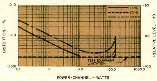
Fig. 1--Power output vs. THD, Pioneer A-9 amplifier.
Using a twin-tone measurement system (with tones 1 kHz apart at around 14 and 15 kHz), I measured a CCIF IM figure of 0.0055 percent, for whatever significance that is. After all, I had to come away with some meaningful numbers for the power amp, didn't I? Turning to the preamplifier and control sections of the A-9, some confidence in my lab procedures was restored, for here I was able to measure the significant performance parameters of the amp. Pioneer has not yet elected to quote S/N ratios and sensitivity in accordance with the new EIA/IHF Standards, so my results will not lend themselves to ready comparisons with the manufacturer's published specs. Input sensitivity for the MM phono inputs was 0.25 mV (for 1-watt output), while for the MC inputs, it was 0.01 mV (10 µV). High-level input sensitivity (again, referred to 1-watt output) measured 14 mV. Overload via the MM inputs occurred with an input level of 300 mV as against 250 mV claimed, and for the MC phono inputs, overload was 20 mV, or fully twice as high as the published 10 mV. Signal-to noise ratio for the MM phono input terminals measured a very high 86 dB, while measured via the MC phono inputs, signal-to noise was a very impressive 79 dB. It is rare indeed that I ever measure MC signal-to-noise ratios in excess of 70 dB using the new standard method (0.5-mV input and volume control adjusted so as to produce 1 watt at the speaker outputs). Referred to 1 watt, with 0.5 volt applied at the input, high level S/N measured 88 dB, while at minimum volume, hum and noise decreased to-94 dB below 1 watt. (That's 114 dB below rated output of 110 watts, or fully 4 dB better than claimed by Pioneer.) Frequency response via the high-level inputs was flat from 3 Hz to 80 kHz (-3 dB), while RIAA equalization via the phono inputs was virtually perfect to well above 20 kHz and down to 20 Hz. The general shape of the RIAA playback curve is shown in the sloping trace of Fig. 2; the horizontal line shows the flat output obtained via the record-out terminals when a signal having inverse RIAA characteristics was fed into the MM phono inputs. Range of sweep (performed on a Sound Technology Model 1500A microprocessor-controlled tester) extended from 20 Hz to 40 kHz. To emphasize the accuracy of the RIAA equalization provided by this amplifier, I expanded the sensitivity of the display in Fig. 3 (note the legend at the lower left, 2 dB/ division as opposed to 10 dB/division in Fig. 2), and, as you can see, the response was virtually flat to well above 20 kHz.
Range of the dual turnover frequency bass and treble tone controls on the A-9 is plotted in the spectrum analyzer/'scope display of Fig. 4. The advantage of having this type of tone control is at once apparent, since, using the extreme turnovers (200 Hz for the bass and 5 kHz for the treble), it becomes possible and practical to tweak the ends of the audio spectrum without affecting important midrange response. The-3dB cutoff point of the subsonic filter occurred at a frequency of 16 Hz.
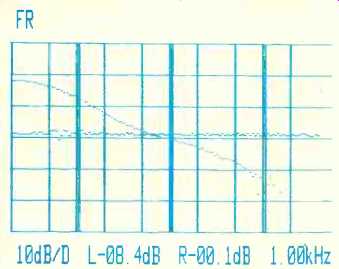
Fig. 2--RIAA playback response of equalizer section of A-9 amplifier (sloped
curve) and output of preamp section when fed with inverse RIAA input signal
(horizontal curve).
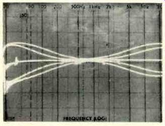
Fig. 4--Bass and treble tone control range at each turnover setting. Plot
is from 20 Hz to 20 kHz (logarithmic) and vertical scale is 10 dB per division.
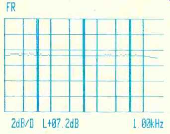
Fig. 3--RIAA response of A-9 amp was extremely flat to beyond 20 kHz, expanded
scale.
Use and Listening Tests
The new panel layout of this Pioneer integrated amplifier contributes a great deal to its ease of use. As for the circuitry innovations inside, while I cannot honestly establish a correlation between Pioneer's "non-switching" output stages and the quality of sound that I heard, I can tell you that the sound quality of the A-9 was excellent. The amplifier handled the most complex transients that I was able to feed it with an effortlessness and openness which I have come to recognize from some of the better amplifiers produced in the last couple of years. In comparing this amplifier with others in the same price and power category, I would suggest that you audition at moderate listening levels--even low listening levels--in addition to the usual "pushing for maximum undistorted output" tests. It is at the lower test levels that you are likely to hear the more subtle differences between an amplifier such as the A-9 and lesser competition.
If the "straight line" tone control bypass feature was de signed to show how much better an integrated amp can sound when signal processing or response altering circuits are bypassed, I'm afraid I was not convinced. Call it a backhanded compliment, if you wish, but I could distinguish no difference in sound quality with the "Line Straight" depressed or not de pressed. Perhaps the source material I used for these tests wasn't sufficiently demanding, or perhaps this sort of comparison test is just too subtle for my ears, though I doubt it. In any case, I liked what I heard whether the tone controls were in-circuit or out, so there's no harm in having the feature for those who hear, or think they hear, a difference when they punch that switch.
-Leonard Feldman
(Adapted from : Audio magazine, Dec. 1981 )
Also see:
Pioneer SX-V90 Audio/Video Receiver (Equip. Profile, Jan. 1985)
Pioneer Model SX-1980 Stereo AM/FM Receiver (Equip. Profile, Sept. 1978)
Fisher RS-Z1 Receiver (Aug. 1990)
Phase Linear Model 1100 Series Two Parametric EQ (Dec. 1981)
= = = =