Phase Linear Model 1100 Series Two Parametric EQ
Manufacturer's Specifications
Output: 2.0 V rated, 8.0 V maximum.
THD + N: 0.02 percent.
IM Distortion: Less than 0.02 percent.
Frequency Response: 20 Hz to 20 kHz, + 0,-1 dB.
S/N: 100 dB re 2.0 V.
Amplitude Range: ±12 dB.
Bandwidth: 0.18 to 1.8 octaves. continuously adjustable.
Center Frequencies: 63 Hz, 250 Hz, 1 kHz, 4 kHz, and 16 kHz.
Center Frequency Adjustment
Range: 9 to 1, from 1/2 x f_ctr to 3 x f_ctr.
Dimensions: 19 in. (483 mm) W x 51/2 in. (140 mm) H x 8 in. (203 mm) D.
Weight: 9 1/2 lbs. (4.3 kg).
Price: $595.00.
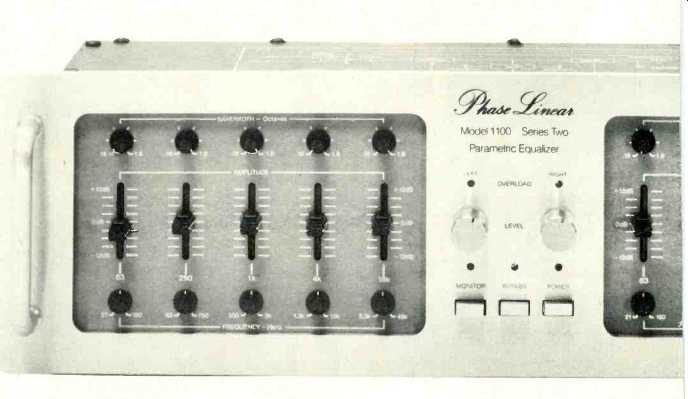
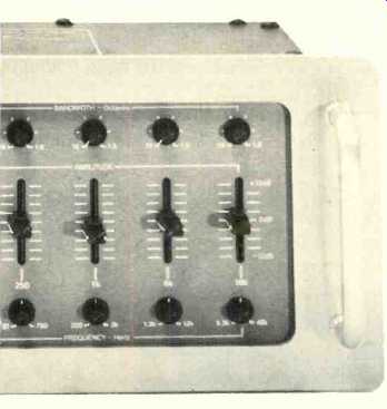
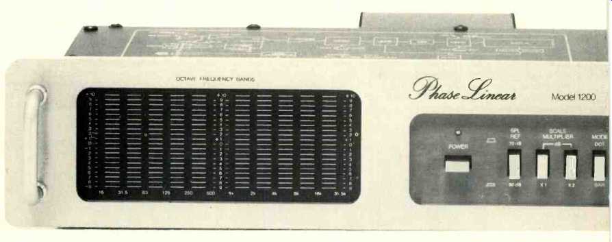
The Phase Linear Model 1100 Series Two parametric equalizer continues the attractive front-panel design of the Series Two units with the majority of the controls inset slightly against a sub-panel of darker tone. The 1100 gains immediate interest because it is a parametric equalizer, as opposed to the more common graphic EQ units with octave-spaced filters. The Phase Linear unit provides some graphic information by using 10 vertical sliders for boost/cut control, five for each channel, with a good range of ±12 dB and a gentle, but definite, detent at 0 dB. With the frequency adjust controls in detent at the center of their rotation, the filter center frequencies are at 63 Hz, 250 Hz, 1 kHz, 4kHz and 16 kHz, quite well chosen for covering the entire band. The frequency range of each filter from minimum to maxi mum is 21 to 190 Hz, 83 to 750 Hz, 330 Hz to 3 kHz, 1.3 to 12 kHz and 5.3 to 48 kHz, respectively. Thus, there is more than an octave overlap possible with adjacent filters, of definite benefit at times. Each bandwidth control has a range from 0.18 octave to 1.8 octaves, continuously adjustable. The knobs on these controls, and the frequency-adjust pots, are very small, making them hard to turn.
Between the two EQ-control sections are two pots to set channel EQ gain, from off to +6 dB. Overload lights are located above the pots, a desirable feature where EQ can cause very high levels. However, the 1100 lacks a scheme for matching EQ in /EQ out levels to prevent sudden jumps in system sound levels. There are push-button switches for Bypass (EQ out), Monitor (Tape Play fed to unit) and Power, each with a status light. A helpful signal-flow diagram is quite handily included on the top cover. The EQ in/out and tape record/play phono jacks are all on the rear panel.
Removal of the top cover revealed a full chassis-sized mother-board with a number of discrete components and 12 plug-in p.c. boards: Left arid right sets of five filter channels and a level card. The EQ cards each had a color spot, coded to the matching spot next to the socket on the mother-board. The sold ring was excellent, with very little flux residue. All ICs were in sockets, an aid to servicing; on the other hand, there was no parts identification.
Measurements
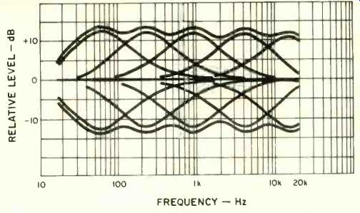
Fig. 1--Swept-frequency responses with and with out EQ; controls flat, each at maximum boost and also cut individually; all controls at maximum boost and at maximum cut. (Bandwidths set at maximum, 1.6 octaves.)
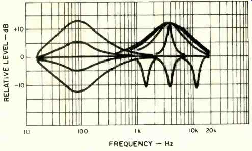
Fig. 2--Response with lowest filter set to maximum bandwidth and 90 Hz, and gain control set to-12,-6, 0, +6, and +12, successively. Responses with 4-kHz filter at maximum boost with four bandwidth settings, and at maximum cut and minimum, center, and maxi mum frequency.
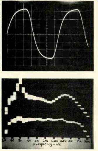
Fig. 3--Output at maximum gain with 1.5-V 30-kHz square-wave input. (Scales:
Vertical, 1V/div.; horizontal, 5 µS/div.)
Fig. 4--Top, response of "speaker" before EQ; bottom, response after EQ. (Scale: Vertical, 5 dB/div.)
The first checks of the 1100 EQ characteristics were made with all of the frequency-adjust controls in detent. A series of swept-frequency responses were taken as shown in Fig. 1. The response with EQ but with all sliders in detent was within a small fraction of a dB from 20 Hz to 20 kHz. The 3-dB down points were at 9 Hz and at 46.9 kHz; without EQ (in Bypass), they were at 8 Hz and 89.3 kHz. Plots were also made of each of the filter sections at maximum boost and cut while set to maximum bandwidth. Finally, responses were run with all filters at maxi mum boost, and then at maximum cut. It can be seen that filter shapes are very much the same, and that all of the boost and cut maxima are very close to 12 dB from zero. The combining of the outputs is fairly good, with 2 to 3 dB ripple.
Additional tests were conducted to illustrate the versatility of the 1100 parametric EQ. The first plots made in Fig. 2 show the results of adjusting the amplitude parameter with the lowest filter, set at 90 Hz. Sweeps were made for settings from-12 to +12 dB. Next, the 4-kHz filter was set to maximum boost, and four sweeps were made with different settings of the bandwidth parameter. Finally, the 4-kHz filter was set for maximum cut and minimum bandwidth, and the frequency control parameter was varied from nominal to minimum, and to maximum for successive sweeps. There are many other possibilities, of course, but Fig. 2 emphasizes the three basic parameters that can be varied. The reader should understand that all combinations can be used, such as moving a filter up in frequency at the same time that the response is boosted and the bandwidth made more narrow. Equalizers without facilities for adjusting these three parameters are not classified as true parametric.
With the frequency adjust pots in detent, the frequency of peak responses were generally within 3 percent of spec, very good. The 1-kHz filter peak was almost 10 percent low, but such a discrepancy is definitely not a problem, especially with a parametric equalizer. The frequency range was as specified, from 1.3 to 12 kHz for the 4-kHz filter, for example. The bandwidth at maximum boost agreed with the spec, but the change from 0.18 octave to 1.8 octaves occurred in less than half the rotation of the pot. A spreading out of the effective changes and a calibrated scale appeared to be in order.
The input impedance was 44 kilohms over most of the band, falling slowly at the high end to 23 kilohms at 20 kHz, plenty high enough in any normal circumstances. The output impedance was less than 8 ohms, which is very low and most unlikely to be affected by any loads that are connected. The maximum voltage, just below clipping, was 7.8 V over most of the band, falling slightly to 7.5 V at 20 kHz. The overload indicator turned on at about 0.4 V lower (7.4 V) for most of the band, but required a higher voltage (8.4 V) at 20 kHz. The input over load level was close to 30 V. The output polarity was the same as the input, with and without EQ.
The harmonic distortion with 1-V in and 2-V out was 0.0026 percent at 20 Hz, 0.0020 percent at 1 kHz, and 0.016 percent at 20 kHz--all excellent figures. The SMPTE IM distortion was about 0.005 percent up to 2-V output, rising to 0.01 percent at 3.5-V output. With all controls at +12 dB and the gain adjusted for 2.0-V output, THD plus noise was 0.002 percent, with HDL2=0.0012 percent and HDL3=0.0015 percent. These are certainly most excellent figures, achieved even with the maximum boost. With 1-V in and controls set flat, the distortion was just 0.12 percent at 100 kHz. Figure 3 shows the output of the 1100 with a 2.0-V, 30-kHz square wave in. The rounding of the waveform shows the result of the small-signal high-frequency roll-off which actually prevents the unit from reaching a slew limit. The tests indicated that the slew factor is somewhat greater than 5, the specified figure. The signal-to-noise ratio was greater than 100 dBA, referred to 1 V with 1-kilohm input terminations.
The noise was less than 10 µV, A-weighted, and that was the lower limit of the test equipment.
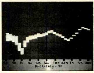
Fig. 5--Response of EQ used to smooth "speaker"' of Fig. 4.
(Scale: Vertical, 5 dB/div.)
In-Use Tests
The illustrations in the 28-page owner's manual are generally very good and include filter-response curves, a schematic, and a "house curve" with a recommended high-frequency roll-off. The text discusses EQ by ear, by hand with a record and an SLM, and by eye--with particular reference to the Model 1200 Series Two RTA. There are some oddities in the text that could be confusing to the neophyte. For example, in referring to a 6-dB boost at 60 Hz, this statement is made: "The frequencies around 60 Hz are made twice as large as those around 1 kHz." To show the versatility of the Model 1100, a speaker output was simulated using pink noise and a 1/3-octave equalizer. The top display in Fig. 4 shows the "speaker" response with a 10-dB peak around 80 Hz, falling response around 1 kHz at the crossover, a broad peak around 3.15 kHz, and a falling response above 5 kHz. What is simulated is pretty bad, and audiophile speakers should be much better than this. But what is possible with EQ? The bottom display in Fig. 4 is the result after a few minutes of adjusting the 1100. The roll-off from 1 to 10 kHz is purposeful, and the response was allowed to drop rapidly above that point. Note that variations over the rest of the band are simply gone.
The response of the 1100 with the EQ used is shown in Fig. 5. Note the narrow-bandwidth cut used to remove the 80-Hz peak, with other shaping of a rather broad nature. The actual settings used were:-11 dB at 80 Hz with narrow BW,-1.5 dB at 200 Hz with narrow BW, +3 dB at 1 kHz with medium BW,-4 dB at 4 kHz with medium BW, and +3.5 dB at about 14 kHz with medium BW. The procedure was a simple matter of adjusting all parameters necessary while watching the 1/3-octave display. Repeating the process with an octave-band RTA (Phase Linear Model 1200) gained almost exactly the same results in the final "speaker' response. The advantage gained with the parametric EQ over the octave-band type in such cases is that a fairly accurate inverse response curve can be made with the parametric, matching a peak with a notch, setting bandwidth to match shape, and sliding frequency for exact alignment. The disadvantage of any parametric equalizer is that it can generate unusual and unmusical responses, and for the best results, careful listening and good metering (such as an RTA) are required.
There are quite a few parametrics with three EQ sections per channel, but the 1100 has five filters, all of which aided in the smoothing discussed above. This is a definite plus for this unit, in comparison to other EQs with fewer sections. Larger knobs would be of aid in making frequency and bandwidth adjustments, and spreading bandwidth changes over the entire pot rotation would facilitate making adjustments. A gain-match scheme for EQ/bypass switching would reduce level jumping.
At the least, there should be 0-dB gain index marks for the channel level pots. Other characteristics on the plus side are very low distortion and noise and excellent ranges of adjustment for handling most any audiophile EQ tasks. The Phase Linear Model 1100 parametric equalizer has a higher price than the, great majority of octave-band EQs, but it can do many things none of them can.
--Howard A. Roberson
Phase Linear Model 1200 Series Two RTA
Manufacturer's Specifications
Bands: Twelve, from 16 Hz to 31.5 kHz.
Range: 20 dB with 1-dB steps, 40 dB with 2-dB steps.
Display Mode: Dot (single LED) or bar (LED column).
Rate: Instantaneous peak attack with decays of 20 dB/S (Fast) or 2 dB/S (Slow).
Filters: Two-pole pair to Class I requirements of ANSI Standard S1.11-1966 (R1975).
Line Input Sensitivity: 7 mV for 0-dB indication.
Sound Level Range: 52 to 100 dB SPL.
Microphone Response: 20 Hz to 20 kHz ±2 dB, random incidence.
Pink Noise Output: 300 mV rms, 16 Hz to 20 kHz ±1 dB.
Dimensions: 19 in. (483 mm) W x 3 1/2 in. (90 mm) H x 8 in. (203 mm) .
Weight: 10 lbs. (4.5 kg).
Price: $675.00.
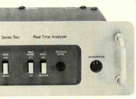
Phase Linear Model 1200 Series Two real time analyzer adds up to quite a mouthful, so we'll shorten its title to the "1200 RTA." This unit's attractive front panel gives a definite impression of quality. There is low contrast between the function labels and the panel background, which may present a legibility problem in low-level light situations. A row of push-button switches provide selection of Power (on/off), SPL REF(70/80 dB), Scale Multiplier(X1 /X2), Mode(dot/bar), Rate(fast/slow), Pink Noise (on/off), and Input (mike/source). The SPL-reference selector effects a change in the mike amp gain, and the choice of 70 or 80 dB SPL is a good one for most audiophile usage. The display scale from "-9" to +10" gives a nominal 20-dB range with X1 and a 40-dB range with X2. The Dot display mode has just the level-indicating LED illuminated in each channel. In Bar, however, all other LEDs below these will also be on, making a bar-graph type of display. Rate sets the decay rate of the display in each of the bands. Possible combinations would be X1, Dot and Slow for equalizing with pink noise, and X2, Bar and Fast for monitoring music, a useful collection of choices.
Source is what others might call Line or AUX, and there is the essential level control for matching the input voltage to the display sensitivity. The LED matrix is 20 (level) by 12 (frequency band). Most RTAs in this general class have 10 bands, and the 1200 is unique as it includes 16-Hz and 31.5-kHz bands, which can aid in checking end-of-band performance. Horizontal lines are imprinted on the face, joining each column, to ensure reading the levels correctly. The LEDs are just medium bright, but the panel has low reflectance, so reading a display in normal room lighting is fairly easy. The microphone input jack accepts the supplied electret mike, which comes complete with 20 feet of cable, a table stand, and a tie-clip type holder. One pin of the jack/cable supplies +4 V to the built-in mike preamp.
On the top cover of the 1200 is a signal-flow diagram for handy reference, while on the back panel are the pink-noise output jacks and dual sets of Source input jacks to facilitate any paralleling desired. With the removal of the top cover, the full chassis-size mother-board could be seen, supporting boards for three fitter channels, the pink noise, the sequencer, and the display plug-in. There were also discretes and ICs on the mother-board, with all ICs in sockets. There was a little interference between components on the pink-noise card and the plug from the power transformer, mounted on the back panel outside of the main chassis-a possible aid in eliminating hum pickup.
The soldering on the p.c. boards was excellent, perhaps the best I've ever seen.
Circuit Description
Figure 1 is the signal-flow diagram of the 1200 RTA, and in this form the circuitry is quite easy to understand. As mentioned earlier, the +4 V mike power is fed out via one of the pins of the input connector. The 70- or 80-dB SPL reference is selected at the input of the mike amp. The left and right inputs at Source are summed and amplified, and the Source Level pot controls the output to the mike/source switch. The following buffer amp feeds the bank of 12 filters, which have selection of Fast or Slow decay. "Row Select" scans the outputs of the filter bank under the control of the clock. Each filter output, when selected, is amplified by the log amp and fed to the level logic. This section includes control for 1- or 2-dB per step sensitivity and for dot or bar display mode. The clock also drives the column select Circuit, in synchronization with filter-band selection. The display, therefore, receives level information which is correctly guided to the correct display column sequentially, filter bank by filter bank.
The combination of scanning rate and persistence of illumination and vision results in a display appearing to be continuous and flicker-free. The pink-noise generator has simple on/off control with the output connected to paralleled left and right jacks.
Measurements
The peak responses of all of the RTA filters with a continuous test tone were within ±0.5 dB, with the exception that the 63-Hz filter was slightly more sensitive and the 31.5-kHz channel was a shade less sensitive, excellent performance. The center frequencies of the 12 filters were all within 1 percent of those specified by ISO, superior to .the majority of RTAs. Figure 2 shows the response of the 1-kHz filter, which appeared to be typical; note the crossovers to adjacent channels at-6 dB and that the response was 15 dB down at the center of the adjacent filters. This filter shape provides good rejection of out-of-band energy, but there will be a drop in indicated level with discrete tones shifted away from the center frequencies. In general, this is not a problem when using the unit with pink noise or when monitoring music.
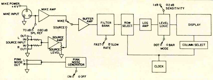
Fig. 1--Signal-flow diagram, Phase Linear 1200 RTA.
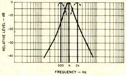
Fig. 2--Frequency response of 1-kHz filter, typical response of 1200 RTA.
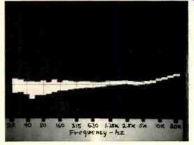
Fig. 3--Spectral output from pink-noise generator. Vertical scale: 5 dB per division.
The 1200 RTA's response, using an Ivie IE-20A pink-noise source, was within 0.5 dB at most points, although there was a sag at the two lowest and highest frequencies of about a dB.
With the built-in generator as the source, there was some low-end droop, but the high end was up about a dB. As a further check, the 1200 RTA generator was fed to an Ivie IE-30A 1/3-octave RTA. It can be seen (Fig. 3) that there is some low-frequency droop and some rise at the highest frequencies. The deviations were less, however, as displayed on the Phase Linear unit, and that's of more importance in the practical use of the 1200. The generator output level was 350 mV rms, and 290 mV rms with the measuring bandwidth restricted to 20 Hz to 20 kHz. The output impedance was quite low, with very little drop in level with a change in load from 50 to 10 kilohms.
The charge times, from "-9" to " +10" as shown on the display, were about 15 mS in Fast and 150 mS in Slow, at variance with the specified "instantaneous peak attack," but fast enough, however. The decay times from " +10" to "-9" were 400 mS for Fast and 4 S for Slow, and the decay rate was fastest at the start. Each of the steps in the display was consistent with increasing level, very close to 0.9 dB for X/ with " +10" at +8.8 dB actual and very close to 1.8 dB for X2 with " +10" at +17.8 dB actual. These are actually very good figures, and plenty close enough for any RTA usage.
The Source input sensitivity was 6.7 mV for a discrete tone and about 20 mV with pink noise, much lower figures than with most units. The input overload, as shown on the display, was at approximately 0.7 V, which is somewhat on the low side and a possible source of problems. A figure of 2 V or more would be desirable. Perhaps some input sensitivity could be "traded" for a higher overload point. I noted that with pink noise fed in directly, the maximum indications with X2 were at " +5" (+10 dB actual), regardless of input level, restricting the total range to 30 dB. With music inputs and different levels from band to band, there was relatively little compression at any point. A number of tests indicated that the microphone sensitivity matched the display reference within a dB or so. Although Phase Linear states that the microphone should be pointed directly at the speakers, I got better results (closer to an Ivie IE-30A) with the microphone turned away almost 90 degrees, close to grazing incidence for the direct energy. The manufacturer states that the microphone is flat ( ±2 dB) with random incidence, which seems contradictory to the instruction of aiming the mike at the direct field. In any event, the microphone is capable of very good response, but it does vary with changes in orientation and the acoustic field conditions. Any user should experiment to see which orientation provides the best guidelines in his listening room.
In-Use Tests
The 28-page owner's manual has a nice open format with very good text and illustrations, including schematic diagrams.
There are a few oddities, however, and the definitions of white and pink noise are incomplete. There is also a system troubleshooting chart, which may be a little complicated for some but is really quite good. The general operation of the 1200 RTA was simple and direct, although there was a little confusion at times on the position of a push-button switch because of the small difference between the in and out positions. All switches and functions were completely reliable throughout the testing period.
Earlier comment was made on the medium-bright display, which turned out to be quite readable with medium-high light levels. I definitely preferred the bar mode, with Fast and X2, for monitoring music. With fairly dim lighting, the 1200 showed one of the best music-monitor displays observed to date. EQ tasks were best in Slow with X2 at the start, switching to X1 for final smoothing. The 70-dB range was a good match for low-level operation, but other in-building activities that generated unwanted noise required the use of the 80-dB range. A 90-dB range would have been helpful in one instance, but this level is tough to take for long if running pink-noise tests. On several occasions, the 16-Hz and 31.5-kHz bands provided additional in sight on the total spectrum. The rather low input-voltage limit discussed earlier could be a problem under some circum stances, but no limitations actually appeared during the in-use tests. The Phase Linear Model 1200 RTA has a higher than average price, for which it delivers flat responses, accurate filtering, accurate SPL calibration, an additional channel at each end of the band, and very good display characteristics.
-Howard A. Roberson
(Adapted from : Audio magazine, Dec. 1981 )
Also see:
Pioneer SX-V90 Audio/Video Receiver (Equip. Profile, Jan. 1985)
Pioneer Model SX-1980 Stereo AM/FM Receiver (Equip. Profile, Sept. 1978)
Fisher RS-Z1 Receiver (Aug. 1990)
= = = =