
by PRASANNA SHAH
[Prasanna Shah is a Senior Systems Engineer for cellular radio and r.f. communications products in the Applications Specific Group of Signetics Company, Sunnyvale, Cal.]
Ever since the introduction of Compact Disc digital audio technology in 1982, the digital-to-analog (D/A) conversion process has gone through continuous refinement to improve the audio quality of the reproduced music.
The technology has progressed from 14-bit D/A converters in 1982 to 20-bit D/A converters in 1989, with various flavors of oversampling from two-times to 16-times. In this article, I will briefly review the existing multi-bit D/A converters and the problems associated with them and then discuss the two basic new one-bit D/A conversion techniques and their advantages.
Today [ca. late 1990], most Compact Disc players employ oversampling digital filters and multi-bit D/A converters to reproduce music from digital information recorded on the optical disc. The digital oversampling filter and interpolation are used to reduce the quantization noise in the analog audio bandwidth, improve the signal-to-noise ratio (S/N), and allow for simpler and lower order, phase-linear, analog post-filtering. Also within the digital oversampling filter, dither, noise shaping and noise decorrelation are implemented to further improve performance. The 18- to 20-bit D/A converters are used to simulate a perfect 16-bit system. Unfortunately, these D/A converters often fall short on audio performance due to severe component nonlinearities. It is important to dispel the myth about achieving 18- to 20-bit accuracy in sound reproduction from a Compact Disc whose digital mastering has only 16-bit accuracy. This can be seen in Fig. 1. The original samples are shown at the two extremes of the analog waveform and the four-times oversampled data points in between. If a signal is reconstructed from the original samples, it would have large steps with very high quantization noise, but if it were reconstructed from the oversampled and interpolated data points, there would be much lower quantization noise.
There are several problems associated with multi-bit conversion techniques. Linearity and gain errors, glitches, slew-rate distortion, zero-crossing distortion, etc. introduce severe harmonic distortion and group-delay differences which influence the audio focus, depth perception, and stability of sound sources in a stereo image. For good-quality sound reproduction, it is essential to use digital to analog converters with excellent performance at low signal levels and high frequencies, though most manufacturers of multi-bit D/A converters specify their components only at 0-dB level and 1 kHz.
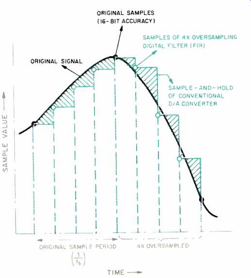
Fig. 1 Typical sampled audio signal; see text.
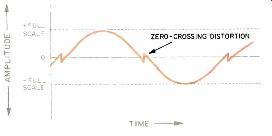
Fig. 2 Zero-crossing distortion in a multi-bit D/A converter.
The absolute linearity error of a D/A converter is the deviation from a constant-step staircase output. This type of error causes distortion at large signal levels, which is only observed when the analog post-filters and amplifiers have virtually no distortion. Differential linearity error is the step-size deviation from one least-significant bit (LSB) at any place in the D/A transfer characteristics, and it introduces audible distortion at low signal levels. In multi-bit converters, binary-weighted current sources are switched according to the binary sample value, which then generates an analog current rep resenting the binary sample value. A good 16-bit D/A converter has to generate the full-scale current with an ac curacy greater than one part in 65,536 (one LSB) of the full-scale current. Similarly, an 18-bit D/A converter has to have an accuracy that is greater than one part in 262,144 of its full-scale current. To achieve such higher accuracies, techniques such as laser trimming of components, segmentation of current-divider networks, or external trimpots for adjustments are utilized.
These external trimming techniques use potentiometers, current-source segmentation, offset cancellations, etc. that can vary over time and tempera ture. Therefore, they can do more harm than good to the consistency of sound reproduction since they are subject to aging and production variances.
The switching of the current sources in a D/A converter produces transients which are known as glitches. These glitches have a significant impact on the sound quality at low signal levels when the ratio of glitch energy to signal level is at its highest. The "de-glitchers" that are used in some systems cause additional linearity problems in the total D/A circuit. When the music signal passes through the zero level, switching of the most-significant bit (MSB) causes zero-crossing distortion, as shown in Fig. 2.
Slew-rate distortion typically occurs in the differential amplifiers used for analog post-filters and deglitchers with D/A converters. The current pulses and glitches produced by these converters have a slope of a few nanoseconds, and their amplitude depends on the signal frequency, signal amplitude, and oversampling rate. The higher the signal frequency and amplitude, the larger the glitches. Because the amplifier bandwidth is low compared to the transition speed of the glitches, the error voltage at the inverting input of the amplifier is determined by the high frequency output impedance of the amplifier and the response of the feed back network. Slew-rate distortion occurs when the error voltages exceed the linear operating range of the amplifier input stage. The slew-rate distortion is usually very severe when high level and high-frequency signals are being converted.
Although commercially available multi-bit D/A converters are typically plagued with the aforementioned problems, there are exceptions, such as the Philips TDA1541A series converters. These converters use a patented technique called Dynamic Element Matching, involving time aver aging of active current dividers (not pass ve ones as used by Analog Devices and Burr-Brown). This cancels any offsets or mismatches in the current sources and circuit components, and it provides a significant improvement in the accuracy of the current dividers, regardless of temperature variations and aging. This reduces the distortion caused by the linearity and gain errors. The Dynamic Element Matching scheme also alleviates the problems of zero-crossing and slew-rate distortion, as the high-speed time-averaging minimizes the glitch energy.
SINGLE-BIT CONVERTERS
To address the problems associated with the multi-bit D/A conversion, two new single-bit conversion techniques have emerged. One of these, pulse-width modulation (PWM), is also known as pulse-edge modulation (PEM) or pulse-length modulation (PLM). The other, the Philips pulse-density modulation (PDM) system, is also known as bitstream conversion. Each bit in the multi-bit D/A converter represents a level in amplitude of the signal. Thus, a 16-bit system has 65,536 discrete levels of amplitude, each corresponding to its 16-bit code. In contrast, the one-bit D/A converters have only one level of amplitude. In the PWM scheme, the pulse width corresponds to the 16-bit data word, whereas in PDM bitstream conversion, the density ratio of the positive or negative pulses is associated with the original 16-bit data word.
PWM CONVERTERS
The PWM technique called MASH (for Multi-stAge noise SHaping, a patented technique developed by NTT of Japan) is utilized by converters such as Sansui's LDCS and Matsushita's MN6471. A typical MASH converter (Fig. 3) is composed of a four-times oversampling digital filter followed by a noise-shaping circuit. (For more information on the noise shaper, the sidebar.) The output of the noise shaper goes into the PWM D/A converters, and the analog output is then low-pass filtered.
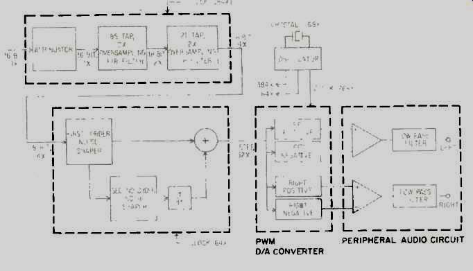
Fig. 3 Block diagram of a PWM (MASH) one-bit D/A converter.
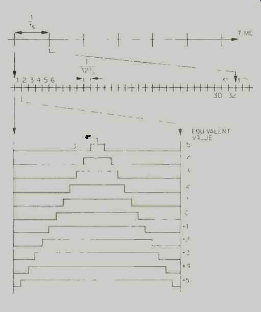
Fig. 4--Eleven-step PWM D/A converter waveforms and their relationship
to original sampling and converter oversampling frequencies.
The digital Finite Impulse Response (FIR) filter has 106 taps and produces 18-bit data from a 16-bit input sample after four-times oversampling. A first-order noise shaper is in parallel with a second-order noise shaper which converts the 18 bits of sample data into an 11-step PWM output. Within the noise-shaper block, the data is eight-times oversampled again to bring the total oversampling to 32 times. The 11-step output waveform drives the two PWM D/A converters, and the opamps finally low-pass filter the analog wave forms. Figure 4 shows the 11-step waveforms from the PWM D/A converter. As the value of the sample is proportional to the pulse widths of each step, it is quite essential that the PWM steps have extremely accurate pulse widths and absolutely minimum jitter to maximize the accuracy and linearity of the converted data.
The entire system is operated from a master crystal oscillator at 768 times the sampling frequency, 33.868 MHz.
A true one-bit PWM conversion of a 16-bit signal would require 65,536 pulses to represent each different amplitude. Unfortunately, this would require the one-bit PWM D/A converter to operate at clock rates in excess of 2.98 GHz, which is not possible even with the fastest bipolar technology available to day. Hence, bit compression is performed and the 18-bit data word is converted into an 11-step PWM output.
These 11-step PWM outputs are then presented to the PWM D/A converter.
Even though each PWM step has a fixed duty cycle with predefined high and low voltage levels, the D/A converter can only be considered a 3.5-bit converter instead of a true one-bit converter because of the 11 quantized PWM steps.
PDM BITSTREAM CONVERTERS
The PDM bitstream technique developed by Philips and utilized in the SAA7322/3 is, however, a true one-bit D/A conversion. The block diagram of the bitstream D/A converter is shown in Fig. 5. The device accepts inter-IC sound (I2S) serial-format data from the decoder chip SAA7310 and feeds the four-times oversampling digital FIR low-pass filter. Higher audio performance is obtained because the non-recursive FIR interpolation filter is phase-linear, with minimum overshoot and fast settling time. Excellent phase linearity reduces phase distortion and minimizes group delay (delay through the circuit that changes with frequency). Excessive group delay will change the tonal qualities and timbre of the music.
The number of reference points for a converter's transfer function depends on the number of bits employed.
With only two reference points, the one-bit converter's transfer function is smoother, causing errors in gain rather than in linearity.
The filter has 128 taps (22 more than the MASH PWM D/A converter) and a 20-kHz bandwidth with a passband ripple of ±0.02 dB. The stop-band attenuation above 24.2 kHz is-60 dB.
First-order noise shaping is performed by the accumulator of the multiplier in the filter. The filter also performs frequency response compensation for the linear interpolator and analog post-filtering roll-off, and performs coefficient scaling to prevent overflow in the noise-shaper circuit. (Figure 6 shows the frequency response of the FIR filter.) The first filter stage shown in Fig. 5 is followed by the attenuator and clip per stage, which provides 12 dB of attenuation during track search.
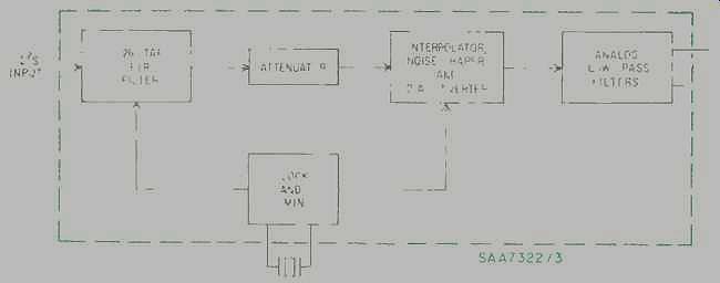
Fig. 5 Block diagram of a PDM bitstream D/A converter.
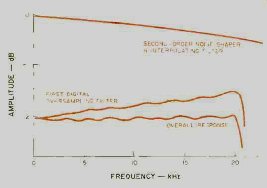
Fig. 6-- Frequency response of FIR filter.
The second filter stage is composed of a 32-times oversampling linear interpolator and a two-times oversampling sample-and-hold circuit. In this stage, a 352-kHz digital dither signal at-20 dB is added to the sample data. This dither reduces the nonlinearity introduced by correlated quantization noise and also reduces any idling pat terns in the noise shaper. This stage brings the total oversampling to 256 times. The 17-bit data at 11.2896 MHz is then fed into the second-order noise shaper. The main function of the noise shaper is to reduce the 17-bit data to a one-bit data stream using sigma-delta modulation and, in due process, redistribute the quantization noise from the audio spectrum to higher frequencies.
The one-bit data stream is then converted into an analog signal by the switched-capacitor network D/A converter, as shown in Fig. 7. When the input data bit is "1," charge p+ is transferred from C1 to C3 on the high clock period (CL); on the low clock period (CL), C1 is discharged. When the input data bit is a "0," the charge is transferred from C3 to C2 on the high clock period and C2 is discharged during the low clock period. Thus, it can be seen that the accuracy of the converter mainly depends on the matching of the two capacitors C1 and C2. With advanced C-MOS technology, it is possible to achieve a very high level of matching accuracy.
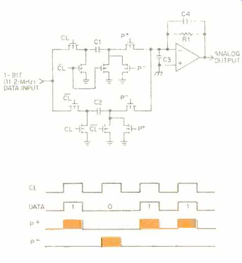
Fig. 7 Simplified schematic and timing diagram of a switched-capacitor one-bit
D/A converter. Components R1 and C3 are external. The p + signals include clock
and data; p- signals include clock and inverse data.
In a single-bit conversion, one voltage reference produces two distinct levels of outputs, a "high" and a "low." In contrast, multi-bit (16-bit) converters produce 65,536 levels from 16 different current sources. As there is only a single voltage reference in the bitstream approach, there is no matching requirement for higher accuracy. This eliminates both absolute and differential linearity errors in the D/A conversion and the audio distortion associated with them.
The zero level, or digital silence, is represented in the bitstream converter by an alternating "101010101010 .. ." pattern (which averages to a zero output level) at 11.2896 MHz. This high speed conversion eliminates any zero-crossing distortion in the bitstream converter. It should be noted that most PWM MASH CD players mute the D/A converter during digital silence instead of producing a true zero-level output, and so the zero-level noise floor specified by these CD players is that of the amplifiers and analog low-pass filters and not the converter itself. If PWM MASH D/A converters do not mute the output at zero level, they can have a much higher noise floor than the PDM bitstream converters. Hence, comparison between the noise floor of CD players based on PDM bitstream and PWM MASH is meaningless.
To generate the positive-going portions of the waveform, a higher density of ones is present in the PDM bit stream, e.g.:
11101011011101011101111...
To generate the negative-going portions, the bit stream will contain a higher density of zeros, e.g.:
10010001000101010001000. . .
This is shown in Fig. 8.
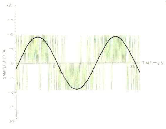
Fig. 8--Simulated PDM output. The pulses above the center line are ones; the
pulses below the line are zeros.
Figure 9 shows the linearity of a one-bit PDM bitstream D/A converter. It can be seen that for most of the normal audio range, the SAA7322/3 PDM bitstream D/A converter is as linear as the ideal characteristics. The multi-bit converter shows severe nonlinearity at low signal levels due to mismatches in the current sources. Since there are no MSB changes around zero level, and a zero is represented by an equal number of full-scale positive and negative pulses, the zero-crossing distortion is absent. Also, there are no major current switches to cause any glitches.
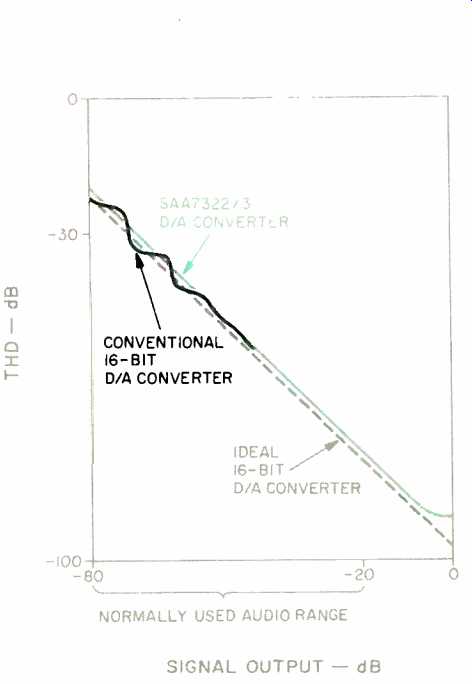
Fig. 9--Linearity error of PDM and conventional 16-bit D/A converters.
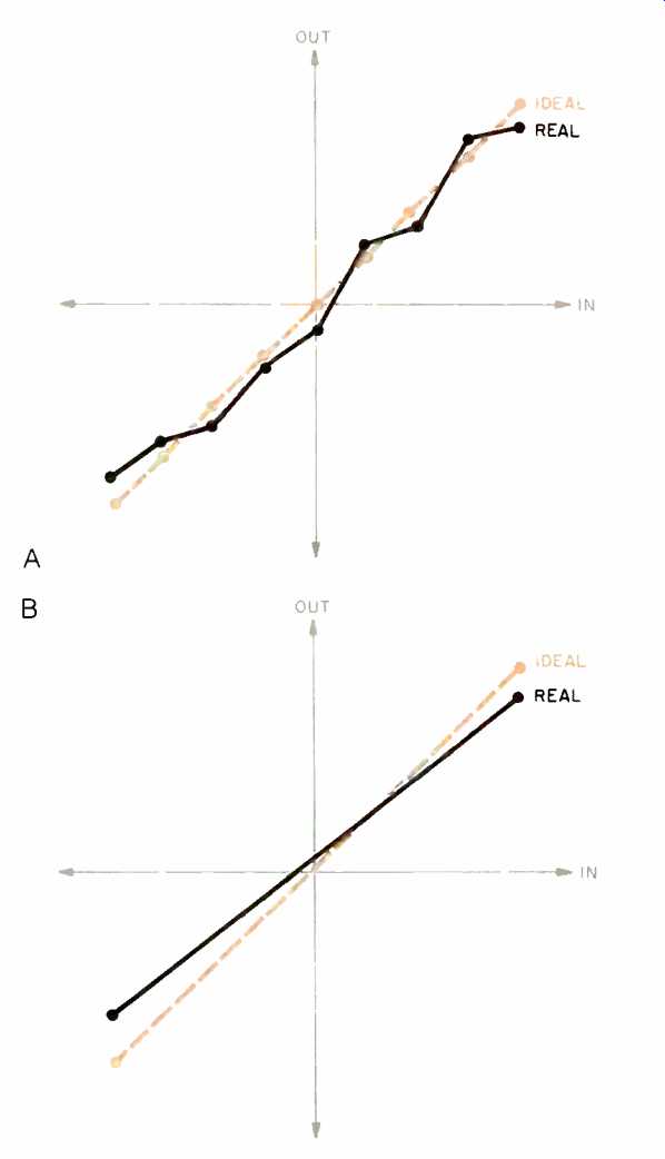
Fig. 10--Transfer functions, showing linearity errors of multi-bit D/A converters
PDM one-bit D/A converters (B).
Figure 10 compares the linearity of multi-bit and PDM bitstream D/A converters. It shows that there is a severe linearity error for the multi-bit system, mainly due to mismatch in components. In contrast, the PDM bitstream converter has absolutely no linearity errors; it only has a gain error which can be attributed to any mismatch in the capacitors of the switched-capacitor D/A converter. This is demonstrated by the fact that the transfer function for the PDM decoder has only full-scale positive and negative reference points, with the intermediate points deter mined by time averaging. Therefore, there is only a gain error in conversion and no linearity errors. The resolution in amplitude for the multi-bit D/A converter is replaced with accuracy in time for the one-bit D/A converter. Since the timing reference is derived from a quartz oscillator, very accurate conversions are possible.
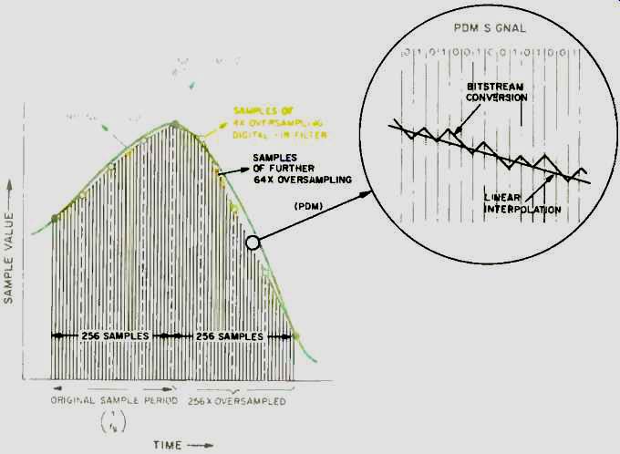
Fig. 11 Response of 256-times oversampling PDM bitstream D/A converter
to the sample data signal of Fig. 1.
Figure 11 shows the response of a PDM bitstream D/A converter to the sample data signal of Fig. 1. It can be seen that the reconstructed signal is very close to the original signal. And because of the 256-times oversampling, interpolation, and noise shaping, the quantization noise is very much reduced compared to the four-times oversampled signal reconstructed by a multi-bit D/A converter.
It is very interesting to compare the various multi-bit and single-bit D/A conversion techniques for linearity error and THD performance. Figure 12 shows the linearity error of six different CD players with these various D/A converter systems. It can be seen that the one-bit converters have minimum linearity error, whereas some of the very expensive CD players with 18- to 20- bit, four- to eight-times oversampling D/A converters have as much as ±3 dB of error at low signal levels. This is due to the mismatches in the current dividers of their multi-bit D/A converter circuits.
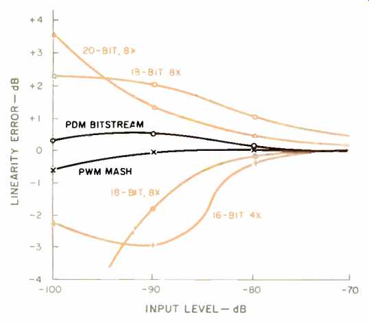
Fig. 12--Comparison of linearity error for one-bit and multi-bit D/A converters.
A THD test performed on these converter systems reveals a very interesting result, as shown in Fig. 13. The test is performed with a - 60 dB, 1-kHz sine-wave signal from the test disc. On the very expensive 18- to 20-bit D/A CD players, the third, fifth, seventh, ninth, 11th, and 13th harmonics (and even the 15th harmonic, in some cases) reach levels greater than -110 dB. On CD players that use the TDA1541A series of dual 16-bit D/A converters with four-times oversampling, only the fifth harmonic is pre dominant, and all the other harmonics are below -110 dB. But the best performance can be seen from the CD players based on the Philips PDM bitstream one-bit D/A conversion technique, which has all of its harmonics below -110 dB.
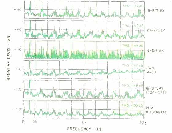
Fig. 13--THD vs. frequency for different D/A converter types.
However, no theoretical analysis or laboratory tests will tell you more about the sound reproduction capabilities than an audition of your favorite CD on one of the many players that utilize one-bit D/A converters.
ACKNOWLEDGEMENTS
I am grateful to R. Finck of Valvo Applications laboratory, Hamburg, Germany, for his help on various tests on the D/A conversion systems. I am also very thankful to S. S. Nethisinghe of Philips Components for his candid discussions on the one-bit PDM D/A conversion process and on second-order noise shaping.
SIDEBAR:
BITSTREAM VS. MASH NOISE SHAPERS
In one-bit D/A converters, 16-bit data is reduced to one-bit data by the sigma-delta modulation algorithm; this reduction in bits is also known as bit compression.
One major problem with bit compression is reduction of dynamic range and increased quantization noise. Noise shaping in the digital domain is a very efficient method of alleviating the dynamic range reduction and noise-floor deterioration in one-bit D/A converters. The main function of the noise-shaper circuit is to change the frequency spectrum of the error signals so that most of the requantization error energy is transposed from the audio band to higher frequencies. This can be seen in Fig. B1.
The block diagram of a third-order, MASH-type noise shaper is shown in Fig. B2. It is actually a first-order noise shaper in parallel with a second-order noise shaper. The input signal is fed into quantizer Q1 after the residual error signal is subtracted from the delay block in the first-order noise shaper. The residual signal is also fed into the second-order noise shaper, where the output of the second quantizer (Q2) is then differentiated and added to the output of the first-order noise shaper to reconstruct the final output signal. Due to physical limitations in VLSI integration and the speed requirements for the MASH converters, the output signal of the noise shaper is translated into 11 discrete PWM steps. In the case of the Philips PDM bitstream D/A converter, a second-order noise shaper converts the 17-bit digitally oversampled and filtered data word into a true one-bit stream.
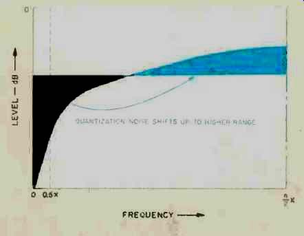
Fig. B1-Redistribution of quantization noise by a noise shaper.
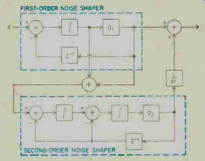
Fig. B2-Block diagram of a third-order noise shaper.
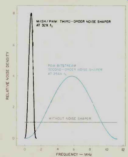
Fig. B3-Noise density vs. frequency for PDM and PWM noise shapers.
The two major factors affecting the performance of the noise shaper are the order of the noise shaper and its frequency of operation. The higher the order of the noise shaper, the higher the slope of the noise redistribution and the lower the noise inside the audio band; thus, more noise is shifted to the higher frequencies.
A major drawback of this increase in noise at higher frequencies is the requirement for a higher order, analog, low-pass filter after the D/A converter. The higher the operating frequency of the noise shaper, the higher the frequency to which the noise is shifted from the audio band.
The noise-density distribution is given by the equation:
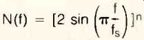
N(f) = [2 sin (π f/ fs)]n
where f is the frequency of interest, fs is the noise shaper's operating frequency, and n is the order of the noise shaper.
Figure B3 shows noise density versus frequency for the MASH and PDM bitstream noise shapers. Since the MASH is a third-order noise shaper, it has a noise peak twice as high as the PDM bitstream. Also, the MASH noise shaper has a lower frequency of operation than the PDM bit-stream and thus has its noise-density peak at a much lower frequency and closer to the audio bandwidth. Thus, the MASH converter will require a much higher order, analog, low-pass filter to reduce excess ultrasonic noise from the output.
A closer look at the two noise-density distributions in the audio band is shown in Fig. B4. It can be seen that from d.c. to 8 kHz, the noise density for both PDM bitstream and PWM MASH is insignificant.
However, as the frequency increases from 8 to 20 kHz and above, the noise level for PWM MASH converters increases significantly, whereas the noise level for the PDM bitstream remains relatively flat. To equivalently reduce the ultrasonic noise for the PWM MASH converters, a much higher order, low-pass filter would be required than is used by the PDM bitstream converter. Thus, it can be concluded that the operating frequency of the noise shaper has more impact on the noise-density distribution than does the order of the noise shaper. Therefore, the PDM bitstream converter has a better noise performance than the MASH converter.
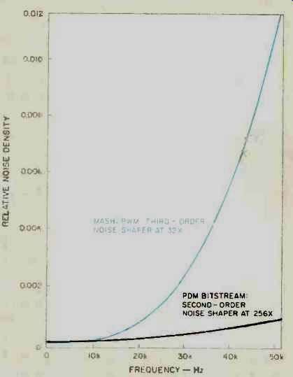
Fig. B4--Noise density in the audio band for PDM and PWM noise shapers.
REFERENCES
1. Nijhof, N., "An Integrated Approach to CD Players, Part 2," Electronic Components and Applications, Vol. 6, No. 4, 1984.
2. Vanderkooy, J. and S. R. Lipshitz, "Resolution Below the Least Significant Bit in Digital Systems with Dither," Journal of the Audio Engineering Society, March 1984 (Vol. 32, No. 3, pp. 106-113); Correction, Nov. 1984 (pg. 889).
3. Dijkmans, E. C. and P. J. A. Naus, "The Next Step Towards Ideal A/D and D/A Converters," Proceedings of the AES 7th International Conference: Audio in Digital Times (pg. 97; May 14-17, 1989, Toronto, Ont., Canada).
4. Finck, R. and Slowgrove, D., "Third-Generation Decoding ICs for CD Players," Philips Elcoma Technical Publication 261.
5. Nethisinghe, S. S., "Introduction to BitStream A/D, D/A Conversion," ICs for Digital Audio, Philips Components.
6. Finger, R. A., "On the Use of Computer-Generated Dithered Test Signals," JAES, June 1987 (Vol. 35, No. 6).
7. Spang, H. A. and P. M. Schultheiss, "Reduction of Quantization Noise By Use of Feedback," IRE Transactions on Communications Systems, Dec. 1962.
8. de Jager, F., "Delta Modulation, A Method of PCM Transmission Using the 1-Unit Code," Philips Research Reports, 1952 (pp. 1,442-1,466).
(adapted from Audio magazine, Jan. 1991)
Also see:
Error Correction in the Compact Disc System (April 1984)
Link | --Philips Oversampling System for Compact Disc Decoding (April 1984)
PWM, PDM, 1-bit converters (Stereophile, May 1989), part 2 (1990), part 3
= = = =