by: Ken C. Pohlmann [Ken C. Pohlmann is a professor of music engineering at the University of Miami in Coral Gables, Florida. He is the author of several books, including Principles of Digital Audio, Third Edition (McGraw-Hill, New Fork, 1995), from which much of this article was drawn.]
Lately there's been a lot of discussion about jitter as a source of degradation in digital audio reproduction. Although the engineers designing the gear have always had to deal with jitter, most audiophiles have probably been left somewhat mystified regarding the causes and consequences of this seemingly new threat-something to dread without knowing quite why. Jitter can add noise and distortion to the analog output signal you eventually listen to, but depending on its severity and where it occurs, you may never hear its effects at all.
Perhaps the most common misconception about jitter is that it is essentially the digital equivalent of wow and flutter in analog systems. There is a germ of truth in that idea, in that both are in the category of what are known generically as time-base errors-inaccuracies or, more to the point for our purposes, Instabilities in signal rate. In the case of LP playback, for example, the turntable is supposed to rotate the disc at exactly 33 1/3 rpm. The inevitable moment-to-moment deviations from that precise speed constitute wow and flutter and manifest themselves audibly (when they are large enough) as pitch instability. The greater the wow and flutter, the more wobble there will be in the reproduced sound. This mechanically induced distortion of the analog wave form also occurs in analog tape systems.
Jitter is fundamentally different in that it consists of timing errors in the transitions that represent bits in a digital data stream, which normally are controlled by very precise quartz-oscillator clocks designed to keep the intervals between them exactly even and correct for the sampling rate. Because we don't listen to the digital signal itself, jitter's effect are indirect rather than direct and, unlike wow and flutter in analog reproduction, never sound like fluctuations in signal speed, even though that is their root cause. What jitter can do is create data errors in the bitstream or add noise or distortion to the signal when it is converted from digital back to analog. So if the inter in a bitstream is allowed to become too great, sound quality may deteriorate.
Jitter can arise when data is read back from a storage medium (such as a CD), transmitted, or processed through circuits such as digital filters and A/D (analog-to-digital) or D/A (digital-to-analog) converters. The extent of the damage caused by jitter, and the complexity of implementing cures for it, depend on where in the signal chain the jitter occurs. Relatively high jitter levels will not prevent error-free transfer of digital signals from one device to another.
When a signal enters or leaves the digital domain, however, conversion must be performed with very low jitter to prevent significant distortion from being added to the playback signal. In extreme cases, a converter's clock might have to maintain timing accuracy to within as little as 20 picoseconds, or 0.00000000002 second.
Figure 1 can help you visualize what such a specification means. Digital jitter can be defined as the time displacement of a clock signal versus a jitter-free ideal reference.
The bottom two pulse trains in the figure are just time-shifted versions of the top one, which indicates a period of uncertainty around each ideal transition time. Jitter may occur as random variations in the timing of pulse edges (white-phase jitter), or it may be related to the width of a clock pulse ("white FM" jitter) or to other periodic or aperiodic events ("correlated" jitter).
One way of observing jitter is to use an oscilloscope to display an "eye pattern" (Fig. 2), consisting of multiple, overlaid waveforms of the digital signal. Indistinct amplitude variations in this pattern indicate noise whereas shifting signal transitions show jitter. As you can see, noise closes the pattern vertically, while jitter closes it horizontally.
An eye pattern shows the dynamic variations in the signal but more insightful method applies the data signal to an FM demodulator connected to a spectrum analyzer: this will make the type of jitter plain, as well as its amplitude and frequency. Random jitter exhibits a broadband spectrum and raises the noise floor in the analog signal reconstructed from the data. Periodic jitter, on the other hand, will appear as a single spectral line, at a low frequency for a slow clock variation or at a high frequency for a fast variation; the reconstructed signal may contain FM sidebands or modulated noise. A jitter measurement may be expressed as a peak-to-peak value or as a root means-square (rms) value; ideally, the measurement's bandwidth should be specified. No single number can define the jitter's spectral content.
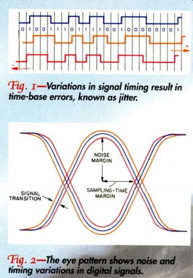
Fig. 1--Variations in signal timing result in time-base errors, known as jitter.
Fig. 2-The eye pattern shows noise a timing variations in digital signals.
Interface Jitter vs. Sampling Jitter
It is important to differentiate between interface jitter (which occurs in digital-to-digital data transfer) and sampling jitter (which occurs when converting data into and out of the digital domain). Interface jitter is not a concern unless it causes uncorrected errors in the received signal. The receiver circuit of a digital input usually will be able to read correct data values in spite of relatively high jitter (and noise) levels in the data, but extreme jitter can diminish the performance to the point where the signal can no longer be retrieved, at which point data errors would result.
In most applications, digital audio data is coded to make it "self-clocking." Downstream circuits can then recover the clock that was used to create the data stream, enabling them to reestablish the time base and lock onto the data signal. It is therefore important for the receiving circuit to synchronize with the incoming bitstream. For example, in the face of unregulated speed variations in a digital tape recorder, a receiving circuit using a clock with fixed frequency would not be able to resynchronize the signal, even if its rate were nominally equal to the signal's clock rate. For this reason, receiving circuits commonly use phase-locked loops (PLLs) to align their clocks with the data rate of the incoming signal.
Although a PLL can provide some jitter reduction, it may not be complete. Consequently, the clock recovered from jittered data will usually be jittered as well. That's significant because jitter remaining in the data stream after it has been received can cause potentially audible artifacts in D/A conversion. Jitter can occur throughout the signal chain and will accumulate (or can be attenuated) as it passes from one circuit to another.
Care should therefore be taken at each stage to decouple the bitstream from the jitter, so data is passed along without data error or conversion artifacts. Fortunately, even a badly jittered signal can be reclocked to an accurate and stable time base, a process known as jitter attenuation. In other words, it is possible to remove jitter from a data signal.
Transport litter
Speed variations in tape and disc transports (especially the former) can create jitter in the data signal. Such variations are cause by eccentricities in the rotation of capstan and spindle motors or other drive components. Clocks and servos must be designed to limit mechanical speed variations, and input and output data must be buffered to absorb timing variation, at least to the point where the data can be passed to or from the transport without error.
Servo control circuits are used to read timing information from the data and generate a speed-correction signal for the tape or CD transport (Fig. 3). In many cases, a phase-locked loop is used to control the servo. Speed control can be achieved with a PLL by comparing the synchronization words in the bitstream (coded at a known rate) to a reference and directing a speed-control servo voltage to the transport to dynamically minimize the difference.
Although phase-locked servo systems can maintain relatively accurate and constant transport speeds, there will still be variations in the data rate off the disc or tape. Such jitter can be removed by reclocking the data through a buffer memory, however. Buffering is normally required anyway (in CD players, for example) for data demodulation and error correction, so transport speed variations need not be a factor in the jitter ultimately seen by the D/A converter. The reason buffering can be used to eliminate transport jitter is that the data output rate from memory can be independent (within reason) of the input rate.
Consequently, an inconsistent data input from the disc or tape does not prevent precise data output. However, the clock con trolling the data readout from memory must be decoupled from the input clock, because it is the output clock's jitter level that will determine the jitter level of the output data.
Jitter in Data Transmission
Jitter occurring when a data signal is conveyed through a transmission channel can have many causes. The magnitude of transmission jitter often depends on cable characteristics. In general, the wider a cable's bandwidth, the lower the jitter level.
(For example, data may be literally error free with a bandwidth of a few hundred kilohertz, but a bandwidth of several mega hertz may be necessary for satisfactorily low sampling-jitter levels.) Data cables are also prone to mismatched impedances and signal reflections from cable ends, so proper termination is important.
Whatever the cause of jitter introduced by the transmitting source and cable, potentially (depending on whether the data will be subjected to conversion) the receiver has two tasks to perform: data recovery and clock recovery.
When data is transferred but will not be converted to analog at the receiver, only data recovery is necessary. Interface jitter is only a factor if it causes data errors at the receiver. (For example, when transferring data from a CD player to a DAT recorder, then to a workstation, and back to the DAT recorder, only interface jitter is relevant to the data recovery.) Nevertheless, jitter attenuation may be required at some points in the signal path so that data errors do not occur. Relatively high jitter levels can be tolerated in transmission (for example, data with 10 nanoseconds of peak jitter can be conveyed without error).
When the data is to be converted to analog, however, clock recovery is also required. Clock jitter is detrimental to clock recovery because it may compromise the receiver's ability to derive a stable clock reference for conversion. Depending on the D/A converter design, jitter attenuation may be essential for satisfactory conversion.
A receiving circuit derives a clock signal from the input data, uses the clock to recover the data, and then regenerates a low-jitter clock, using it as the internal time base to re-clock the data. (For example, a receiver might read a synchronizing field from an input data frame, place the data in a buffer, regenerate the clock, and then output the data with the accuracy appropriate to the destination.) Using a phase-locked loop to remove interface jitter can yield a sample clock that is accurate enough to avoid potentially audible jitter modulation products. To do this, an interface phase-locked loop accepts the received signal as a timing reference, measures the phase error between the reference and its own output, and uses the error to regulate a voltage-controlled oscillator (VCO) within the loop.
Once locked, the oscillator will run at the reference frequency, yet be decoupled from the reference, preventing jitter from passing through the PLL on the output data or output clock.
Some receiver circuits use a two-stage clock recovery process. The first step is clock extraction: The received clock is synchronized so that the data can be decoded error-free in the presence of jitter. An initial PLL uses data transitions as its reference; the PLL is designed to track jitter well, but not attenuate it. At this stage, the sample clock may have jitter, so the recovered data may be sent to a buffer. The second step is jitter attenuation: A second PLL, with low-jitter clock characteristics, locks to the sample clock and retimes it with an accurate reference, providing jitter attenuation. The new, accurate clock is used to read data out of the buffer.
Anyone who routinely copies data between floppy and hard disks can vouch for the reliability of digital cloning. Unlike the noise floor in analog copying, jitter is not inherently cumulative in digital copying.
However, prior to D/A conversion, it is important for a receiver to limit jitter because the clock circuits used in many converters derive a timing reference from the received clock. Alternatively, any converter must clean the jittered signal, to re cover a suitable low-jitter clock.
Jitter in A/D and D/A Conversion
Jitter must be controlled through out the digital audio chain, but it is most critical at conversion points. Jitter must be minimized in the clocks used for both A/D and D/A converters to keep noise and distortion in the output analog waveform as low as possible. Because jitter in a clock signal can increase as the signal moves through wires or circuit-board traces, the low-jitter clock should be placed physically close to the converter.
For lowest noise and distortion, audio samples must also be acquired at the A/D converter with an accurate time base. That is, the sampling rate must remain as nearly constant as possible, with precisely equal intervals between samples. The effects of jitter on an A/D converter's clock can be similar to the frequency modulation used in FM radio: The input frequency acts as the carrier, and clock jitter acts as the modulation frequency. Jitter tolerances tighten as the audio signal frequency increases. Steve Harris [see References] has shown that if white-noise clock jitter with a 2-nano second peak level is applied to a successive-approximation, 16-bit A/D converter that does not use oversampling, then that converter's theoretical dynamic range of 98 dB will be degraded to 91 dB (Fig. 4). Harris estimates that peak jitter of less than 400 picoseconds will result in artifacts that decrease the dynamic range by less than 0.5 dB. By other estimates, a jitter specification of 250 picoseconds will allow 16-bit accuracy from a full-amplitude, 20-kHz sine wave. Only then will the jitter artifacts fall below the quantization noise floor.
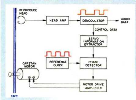
Fig. 3--A pulse-extracting servo-control loop can be used to regulate a
digital tape's speed.
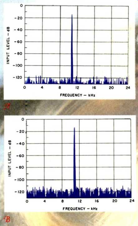
Fig. 4--Simulated noise spectra without o'clock Fifer (A) and with white-noise
clock jitter at a peak level of 2 nanoseconds (B).
The integrity of samples taken from a perfectly clocked A/D converter will be degraded if the D/A converter's clock is jittered, creating the problem of the right samples at the wrong time. The time deviations introduced by jitter will result in increased noise and distortion in the output analog signal. Fortunately, the distortion in the output waveform is a playback-only problem; the data itself may be clean, awaiting only a more stable conversion clock.
The samples are not wrong; they are only being converted at the wrong times.
The severity of jitter's effect on D/A conversion is related to the type of converter.
The worst case for white-phase jitter on a conventional resistor-ladder multibit D/A converter occurs with a full-amplitude signal at half the sampling frequency. Depending on converter design, a jitter level of no more than 1 nanosecond is necessary to obtain 16-bit performance from a resistor-ladder converter. A tolerance of half that level, 500 picoseconds, is not unreasonable.
Some digital components may contain clocks with poor stability, in which case jitter may cause artifacts to appear just 70 or 80 dB below maximum output. When an oversampling digital filter is used in front of a resistor-ladder converter, the converter's sensitivity to random (white-phase) jitter is reduced in proportion to the oversampling rate. Low-frequency (correlated) jitter is not affected by oversampling, however.
Low-bit D/A converters can be very sensitive to clock jitter or not particularly sensitive, depending on their architecture.
When the converter output is a true 1-bit signal, jitter pulses have constant amplitude. In a single-bit converter in which the output is applied to what is known as a continuous-time filter, random jitter is signal-independent, and jitter pulses will appear in the output even when no signal is present.
A peak jitter level below 20 picoseconds may be required to achieve 16-bit noise performance from a 1-bit converter with a continuous-time filter. Some low-bit converters use switched-capacitor ("discrete-time") output filters; because a switched capacitor filter will settle to an output value regardless of when a clock edge occurs, it is inherently less sensitive to jitter. A properly designed switched-capacitor converter's jitter tolerance is similar to that of a resistor-ladder converter operating at the same oversampling rate.
Because jitter control is critical at the D/A converter, and accurate sampling clock recovery is always challenging at the converter, it is more efficient to create a highly accurate master clock directly at the converter and send this clock signal back to the transport, thus controlling jitter at the outset. This is more difficult to engineer when the transport and converter are separate components than when they are integrated, though "master-clock synchronization" facilities are becoming increasingly common in at least high-end CD transports and D/A converters. In most cases, the converter component must receive the digital bitstream and carefully recover a low-jitter clock. Audiophiles have sometimes reported hearing differences between different kinds of digital cables. That could be attributable to a D/A converter whose design is inadequate to recover a uniformly stable clock from the input bitstream. But a well-designed D/A converter with a stable clock will be immune to any variations in the upstream digital signal path, as long as data values themselves are not altered.
Conclusion
Jitter must be controlled at every stage of the digital audio chain. Jitter at an interface is relatively benign, and if a receiving circuit can recover a data signal without error, jitter is not a factor. This is why data can be easily cloned from one device to another without error. Jitter is more critical when sampling, however; an A/D converter must be accurately clocked, and clock recovery is also important prior to D/A conversion.
Although jitter is difficult to measure and completely specify, traditional analog measurements, such as total harmonic distortion plus noise (THD + N), can be used to evaluate the quality of any output signal and will include effects caused by jitter. Indeed, given the wide variation in jitter sensitivity of different converter designs, such measurements are a far more reliable index of performance than measurements of the jitter level itself. For now, jitter is probably not a significant limiting factor in well-de signed, high-quality digital audio equipment, but as new generations of digital for mats and components come to market, with longer word lengths or higher sampling frequencies, the jitter tolerances required to maintain full performance will become more critical.
References
Adams, R. W., "Clock Jitter, D/A Converters, and Sample-Rate Conversion," The Audio Critic, Issue No. 21, Spring 1994.
Dunn, C. and M.O.J. Hawksford, "Is the AES/EBU/SPDIF Digital Audio Interface Flawed?" AES Preprint No. 3360, San Francisco Convention, October 1992.
Harris, S., "The Effects of Sampling Clock Jitter on Nyquist-Sampling Analog-to-Digital Converters," Journal of the Audio Engineering Society, March 1984 (Vol. 38, No. 3).
Harris, S., "The Effects of Sampling Clock Jitter on Nyquist-Sampling Analog-to-Digital Converters and on Oversampling Delta-Sigma ADCs," JAES, July/August 1990 (Vol. 38, No. 7/8).
Katz, Bob, "Everything You Always Wanted To Know About Jitter but Were Afraid To Ask," http://www.panix.com/bobkatz/
Shelton, W. T., "Synchronization of Digital Audio," Proceedings of the AES 7th International Conference, Toronto, May 1989.
Takasaki, Y., Digital Transmission Design and Jitter Analysis, Artech House, Boston, 1991.
Trischitta, P. R. and E. L. Varma, Jitter in Digital Transmission Systems, Artech House, Boston , 1989.
(adapted from Audio, Jan. 1996)
Also see:
Digital Deliverance (Noise shaping, HDCD, etc.) (Apr. 1996)
= = = =