
by EUGENE T. PATRONIS, JR.
INTEGRATED CIRCUITS ARE BEGINNING to bring about extraordinary changes in the electronics industry. These changes are manifested in many ways. The radical differences in the manufacturing processes of integrated circuits as compared with circuits assembled from discrete components are self-evident. In addition, however, there are notable differences in circuit capabilities and in design considerations as well. In general, integrated circuits have a higher circuit density, greater speed, and lower power dissipation than conventional circuits. They lend themselves quite readily to those applications where a large number of circuits of a particular type are required as in computer circuitry. They are finding increasing use in linear circuits 'a here the applications can be tailored to a few standard configurations. RCA, GE, Fairchild, and Texas Instruments among others are each producing lines of linear integrated circuits. Circuit designers will be called upon more and more in the future to design around a few standard integrated circuits or to evolve circuits which can be totally reduced to the integrated form so as to reduce overall costs. An example of a circuit-design innovation which allows a frequency modulation detector to be produced completely as an integrated circuit will be given here.
Frequency-modulation detectors usually take the form of a limiter-discriminator or ratio detector. Both of these circuits depend in part upon a tuned transformer for their operation. The other components in these circuits such as transistors, resistors, diodes, and capacitors can all be produced in the IC form. The transformer can not be integrated at the present stage of IC technology. A circuit not requiring a transformer or other inductors would allow the detector to be produced completely in the integrated form. Clearly, the transformer must be eliminated.
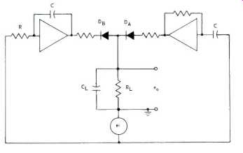
Fig. 1--Circuit proposed by the author for use as a frequency-modulation
detector.
In order to see how this may be accomplished, consider the function which must be performed by the detector. When the detector is presented with a signal whose frequency is fo, the output of the detector is to be zero, When the detector is presented with a signal whose frequency is f, the output of the detector is to he a voltage whose value is proportional to Δf where
Δf=f-fo (1)
In most applications At is no greater than one percent of fo. The fact that the detector output is zero when the input is at a frequency of f, is suggestive of a null or balance technique.
That is, if two signals, say A and B, can be derived from the input signal in such a way that their amplitudes are equal at the frequency fo, then the difference of these two signals will are zero at the frequency fo. Furthermore, if the amplitude of A is an increasing function of fo while the amplitude of B is a decreasing function of f, then the amplitude of the difference signal A-B contains information about Δf.
Let the input signal to the detector be a constant-amplitude sine wave denoted by
ei=E sin(2 pi ft). (2)
From this signal must be derived the two signals A and B. The amplitude of signal A must be an increasing function of f. It is a well-known property of sinusoids that the time derivative is proportional to f. The amplitude of signal B must be a decreasing function of f. This can be given by the time integral of the sinusoid which is inversely proportional to f. Apparently, the signals A and B can be derived from the input signal ei by the operations of differentiation and integration, respectively. These operations can be performed electronically with great accuracy by means of operational amplifiers which can be constructed in the form of completely integrated circuits.
Figure 1 depicts a detector circuit arranged according to the considerations just discussed. The triangles represent inverting amplifiers having large voltage gains for frequencies in the vicinity of fo. The generator represents a frequency-modulated signal source of the form
ei E sin(2 pi ft). (3)
The operational differentiator produces an output signal eA of the form
eA= RC 2 pi f E cos(2 pi ft) (4)
which when rectified by the diode DA and filtered by the network RL, and CL, becomes EA, where
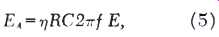
η being the rectification efficiency. The operational integrator produces an output signal eB of the form
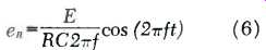
(6)
which when rectified by the diode DB and filtered by the network RL and CL becomes ER where
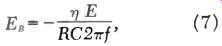
(7)
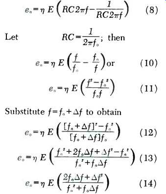
assuming the same rectification efficiency. The output of the overall detector is then e, with
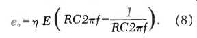
(8)
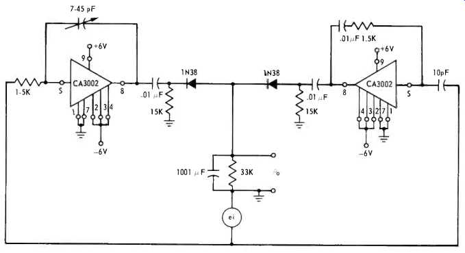
Fig. 2--Details of the final circuit using RCA integrated circuits-CA-3002s-as
a complete frequency-modulation detector. Constants shown are for an i.f.
of 10.7 MHz.
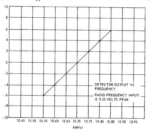
Fig. 3--Curve of detector output vs. frequency. Radio frequency input is
0.25 volts peak.
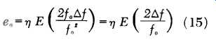
[The derivation of (15) from (8) appears in the appendix.]
If now the integration and differentiation time constant RC is chosen so that
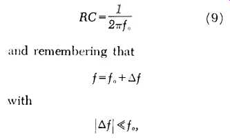
then the output of the detector becomes
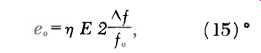
... which is just the desired form. Even though the analysis has been carried out assuming that the signal to be detected is sinusoidal, this assumption is not essential. The input signal might just as well be a square wave, a triangular wave, or other periodic wave shape having an average value of zero.
The A signal will still be proportional to the frequency while the B signal will still be inversely proportional to the frequency.
This detector offers a number of advantages other than the fact that it can be constructed completely in the integrated form. The operational amplifiers provide excellent isolation between the signal source and the detector load. The detector can readily be tuned by varying the time constant RC. This tuning could be accomplished remotely under voltage control by letting C be furnished by a silicon varactor diode, for example. The detector can be used with a wide variety of signal waveshapes and over a wide range of frequencies, fo.
While it is understood that the entire circuit would be feasible in a single IC chip, none is yet available. However, the author assembled the same circuit functions, using a pair of RCA integrated circuits (commonly available at a price of about $4.40 each in small lots) each as the operational amplifiers. The complete circuit of the FM detector developed is shown in Fig. 2, with constants suitable for an i.f. of 10.7 MHz. This circuit, working from an i.f. input of 0.25 V applied at e, produced an output as shown in the diagram of Fig. 3, where e, was measured at6.2 mV for an applied frequency 150 kHz lower than f, and +6.2 mV when the applied frequency was 150 kHz higher than f e. Note that the curve has exceptional linearity over a swing of ±250 kHz each side of the center frequency.
Further development of the circuitry--and the possible introduction of an IC designed for this particular application--would certainly simplify FM receivers and their alignment, an aim that is always justified in this day of electronic simplification.
APPENDIX
To further clarify the derivation of (15) from (8), the following is offered:
In the numerator, Δf2 is much smaller than 2 fo Δ f; therefore we neglect it.
In the denominator, fo Δ f is much smaller than fo2, so we neglect fo Δf.
Therefore with very small error:
=============
(Audio magazine, Feb. 1970)
Also see:
How to evaluate FM stereo tuner performance (Jan. 1972)
Men of Hi-Fi--The Perfect FM Tuner (Jan. 1972)
New Specs for the New Tuners (Jan. 1973)
AM Stereo: An FCC Fiasco (July 1982)
FM Fidelity: Is The Promise Lost? (March 1985)
The Problem with FM (March 1985)
= = = =