MANUFACTURER'S SPECIFICATIONS
IHF Usable Sensitivity: 2.5 µV (13.15 dBf).
Sensitivity for 35-dB Quieting: 2.0 µV (11.2 dBf).
S/N Ratio (Mono): 75 dB. THD (Mono): 0.2 percent, any audio frequency.
Capture Ratio: 2.5 dB.
Selectivity: Normal, 55 dB; Narrow, more than 90 dB; Super Narrow, greater than 90 dB. Spurious Rejection: 100 dB.
Image Rejection: 100 dB. IM Distortion: 0.2 percent (any combination of frequencies).
Maximum Input Signal Across Antenna Terminals: 12.0 volts.
Muting: 70 dB noise reduction.
Muting Threshold: Distant, 5.0 uV (19.2 dBf); local, 20µ V (31.2 dBf).
Stereo Separation: 40 dB @ 1,000 Hz.
Frequency Response: Stereo, 20 Hz to 15 kHz, ±1 dB.
Audio Output Level: Fixed, 2.5 V into 47 kilohms, 1.0 V into 600 ohms; Variable, 2.5 V maximum into 47 kilohms.
(NOTE: Above specifications are stated for "normal" selectivity position unless otherwise indicated.)
GENERAL SPECIFICATIONS:
Power Requirements: 120 V, 50/60 Hz, 35 watts.
Panel Dimensions: 16-in. (40.6 cm) W x 5 7/16-in. (13.8 cm) H.
Chassis Dimensions: 15-in. (38.1 cm) W x 13 (33 cm) D.
Weight: 27 lbs. (12.25 kg).
Price: $899.00
-------------
In recent months, many readers of Audio have commented about the generally "poor quality" of most FM signals received in their listening areas. Almost invariably, these readers go on to question the wisdom of spending a great deal of money on one of the "super-tuners" only to be confronted with FM programs that do not justify such expenditure. This reviewer couldn't agree more, which makes the McIntosh MR-78 an even more interesting tuner than it would otherwise have been, for McIntosh seems to have emphasized a particular aspect of tuner performance that can make a difference in reception-selectivity. But more on this shortly.
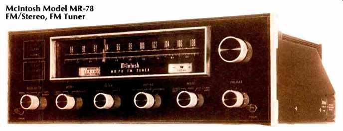
The front panel of the McIntosh MR-78 maintains the traditional "Mac" look of "black glass" and features that company's well-known Panloc mounting method (shelves and shelf mounting brackets, together with necessary mounting hardware are, as usual, supplied). The large, illuminated dial area at the uppercenter of the panel has a linear dial scale, calibrated at every half MHz, as well as a 0-100 logging scale for easy referencing of favorite stations. The smooth-traveling dial pointer is illuminated over a portion of its length.
Also located within the dial opening are symmetrically positioned center-of-channel and signal-strength meters. To the left of the dial area are two rectangular areas denoted as "function" and "selectivity." Illuminated words "stereo," "filter," and "muting" appear (when selected) in the upper area, while the lower area is illuminated with either the notation "-7 dB," "-22 dB," or "-55 dB." These correspond to the three settings of the selectivity switch just below. The dB numbers represent adjacent channel selectivity and should not be confused with the more familiar alternate channel selectivity values which are, of course, much greater. A large tuning knob, coupled to a backlash-free flywheel and dial string arrangement, is located to the right of the dial area opening.
In addition to the selectivity selector switch, other rotary controls along the bottom section of the front panel include a meter selector switch, which chooses either the signal strength or multipath-indication function of the signal strength meter; a filter switch which, in addition to having an "off" position, has two settings for noise reduction during weak-signal stereo FM reception; a muting switch, with positions for local and distant reception (which vary the muting threshold); a mode switch with "stereo only," "mono," and "stereo auto" positions, and a volume control which also turns power on and off to the tuner.
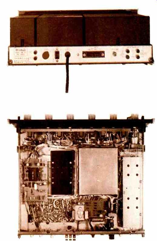
The rear panel of the MR-78 has a pair of test points which are intended for use with the McIntosh Maximum Performance Indicator, an accessory product marketed by that company. A fuseholder cap is also accessible from the rear for replacement, if necessary, of the tuner's 0.5 ampere sloblow line fuse. Push-type terminals are supplied for 300 ohm antenna transmission line connection, while a 75-ohm coaxial connector is offered for connection of that type of transmission line. Two sets of audio output jacks (one pair for fixed output, the other controlled by the front-panel volume control) and one convenience a.c. receptacle complete the rear panel layout.
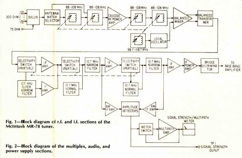
Fig. 1--Block diagram cf r.f. and i.f. sections of the McIntosh MR-78 tuner.
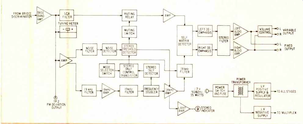
Fig. 2--Block diagram of the multiplex, audio, and power supply sections.
Internal Construction and Circuit Highlights
As can be seen in the internal view of the chassis, the McIntosh MR-78 is extensively shielded. Six major circuit board modules are used in addition to the r.f. front end.
These include the i.f. circuit board, the selectivity junction board, the multiplex section, and the power supply circuit board. The front end utilizes a five-section tuning capacitor.
A junction FET is used as an impedance converter to drive a 5-watt power transistor in the r.f. stage for high overload capability. An antenna matching circuit at the r.f. input has a two-position selectable switch which alters the r.f. bandpass characteristics of the input circuit. The switch positions are labeled "Lo Gain" and "Hi Gain," a bit confusing unless the user reads the manual carefully and discovers that the gain references refer to the antennas which might be used with the tuner. Thus, the "Lo Gain" position is intended for use in seeking out distant or weak signals while, in most applications, the "Hi Gain" position should be used since it yields the lesser amount of r.f. signal at the input to the r.f. amplifier stage, as well as a sharper bandpass characteristic.
A block diagram of the r.f. and i.f. sections of the MR-78 is reproduced in Fig. 1. A balanced integrated circuit mixer stage is used as a further safeguard against possible overload and to reduce oscillator pulling. Its 10.7 MHz output is coupled to the i.f. amplifier section by means of a bifilar transformer. Linear phase filters are used in both the "normal" and "narrow" selectivity settings of the MR-78, while for the "super narrow" selectivity setting a 4-pole 4-zero crystal filter having constant delay is introduced into the i.f. chain. McIntosh developed a new type of FM detector for this tuner which they call a linear phase bridge discriminator. It uses a balanced transmission line bridge in conjunction with a differential voltage doubling circuit to achieve ultra-low orders of distortion in the demodulated FM audio signals.
A block diagram of the multiplex and audio sections is illustrated in Fig. 2. An IC audio amplifier with over 120 dB of negative feedback in two feedback loops is used to drive the stereo demodulator. Muting, "stereo only" tuning, and automatic mono/stereo switching are all performed within the stereo decoder circuitry. A stereo filter circuit follows the matrix decoder and de-emphasis networks to reduce noise when tuning to weak stereo stations. This filter employs a twin-T bandpass filter design to suppress noise while only minimally affecting stereo separation and imaging. The audio amplifier section consists of a pair of two-transistor amplifiers, one for each channel. Each amplifier delivers 2.5 volts to the fixed output jacks and to the volume control sections which feed the variable output jacks. The power supply section consists of a 24-volt regulated supply, which uses electronic filtering and supplies power to all signal stages, while a second, half-wave rectifier supply, also equipped with electronic filter circuits, feeds the necessary d.c. voltages to the multiplex decoder section.
Laboratory Measurements
Although most listening situations require selectivity settings of "normal" on the MR-78, we decided to measure performance in this setting as well as in the "narrow" selectivity setting. In the "normal" setting, IHF sensitivity measured 2.0µV (11.2 dBf) and 50-dB quieting was reached with an input signal strength of 3.0 µV (14.7 dBf) in mono. Referring back to the published specifications, readers will note that McIntosh has not brought their specs into line with the newly adopted IHF/IEEE/EIA FM tuner measurement standards. Thus, no claim is made for 50-dB quieting sensitivity, for example, and Mac offers us a 35-dB quieting point instead. While we recognize that McIntosh has, in the past, differed with the rest of the industry in the matter of publishing specifications, we do feel that the new tuner standards are worth following and would hope that if it has not already been done, McIntosh would bring later published specs into line so that they might be easily compared with those of other companies. Be that as it may, 3.0 µV (14.7 dBf) is a very respectable figure for 50-dB quieting. Stereo sensitivity was 4.5 µV (18.3 dBf), at which signal strength in stereo was sufficient to cause nearly 35 dB of quieting. The 50-dB quieting point in stereo was attained with an input signal of 324V (35.3 dBf). Ultimate S/N in mono was an incredibly high 81 dB (we never thought our signal generator could read that low--now we know it can), while in stereo, best quieting for strong signals was 73 dB. Total harmonic distortion in mono was a low 0.06 percent, while in stereo, for the same strong signals used, THD read 0.1 percent at 1 kHz. Curves of results obtained in the "normal" selectivity setting are plotted in Fig. 3.
Switching to the "narrow" selectivity setting, S/N readings in both mono and stereo remained virtually the same, but, as was to be expected, THD readings increased slightly, to 0.08 percent for mono and 0.35 percent for stereo. These results are shown in Fig. 4.
Returning to the "normal" selectivity setting, we measured a capture ratio of 1.8 dB. Alternate channel selectivity was 57 dB for this setting, while image and spurious rejection were both in excess of 100 dB (the limits of our test equipment). Maximum deviation from ideally flat frequency response, for both mono and stereo, was less than 1.0 dB, with the deviation approaching that number at 15 kHz but remaining within 0.2 dB for frequencies from 10 kHz down to 50 Hz. Muting threshold occurred at 7.0µV for the "distant" position, 30µV for the "local" position. Stereo switching occurred at around 4.0µV (17.2 dBf). Stereo separation measured around 52 dB at mid frequencies for the "normal" selectivity position, decreasing to 43 dB at 100 Hz and 26 dB at 10 kHz, as plotted in Fig. 5. In order to properly ascertain the THD produced by the tuner at high modulating frequencies, it was necessary for us to employ our spectrum analyzer and to "sum" the harmonic products mathematically to arrive at the 0.14 percent THD figure shown for a 10-kHz modulating frequency. If this is not done, non-audible products (not properly identifiable as harmonic distortion) "cloud" the single-reading measurement that is obtained on a conventional meter-type distortion analyzer.
Fig. 6 is a plot of separation versus frequency with the selectivity control set to the "narrow" position. Separation naturally suffers somewhat when this narrow setting is used, but remains well above 30 dB for most frequencies tested.
Distortion in stereo also rose somewhat in the narrow setting, as shown in the curves of Fig. 6., while in mono, THD remained incredibly low at mid-frequencies even when the "narrow" setting of the selectivity switch was used. Sub-carrier product rejection was so good that it was not even necessary to use the recommended 15-kHz low-pass filters for all of our high-frequency noise and distortion measurements, except as already noted for the 10-kHz readings. Audio output level was exactly 2.5 volts, as claimed, for a 100 percent modulation signal at the fixed output terminals.
Since our own signal generating equipment is limited to 0.2 volts output, there was no way for us to verify McIntosh claims regarding 12-volt antenna input-overload capability, though we have no reason to doubt the claim based on subsequent strong-signal listening tests. We purposely carted the tuner over to a mid-city location where we have access to a listening room that is just a few blocks away from several high-powered FM transmitters. Previously, we had measured signal voltages of 2 to 3 volts at that location and found that most tuners did exhibit cross-modulation and other overload effects. With the Mac tuner, we were able to clearly separate closely spaced, high-signal stations on the dial with nary a trace of interference from other strong-signal stations in the same vicinity.
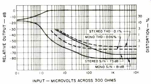
Fig. 3-FM quieting and distortion characteristics with selectivity switch
set to "normal."
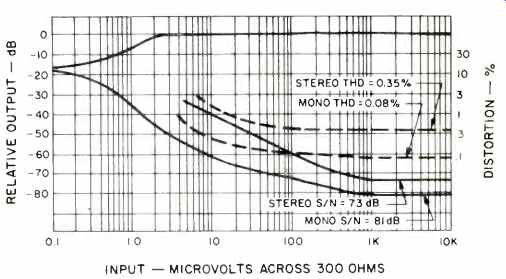
Fig. 4-FM quieting and distortion characteristics with selectivity switch
set to "narrow."
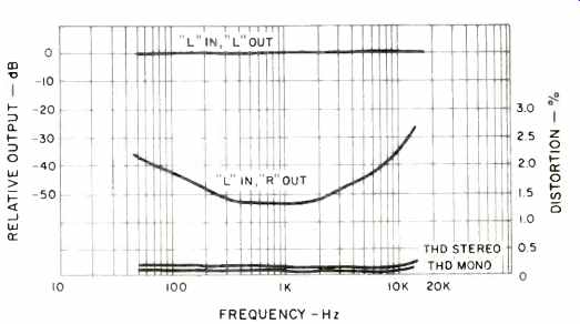
Fig. 5-Separation and distortion vs. frequency with selectivity switch set
to "normal."
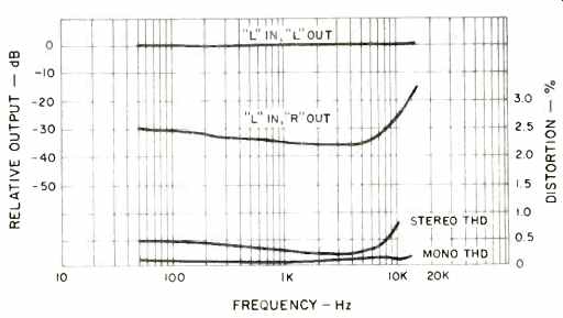
Fig. 6-Separation and distortion vs. frequency with selectivity switch set
to "narrow."
Use and Listening Tests
Back in our own lab (some 20 miles from the city), we began to appreciate the importance of that selectivity switch on the front panel. If you are an inveterate FM DX-er, you will be amazed (as we were) at how many signals you can separate and receive clearly by using the "narrow" (and at times even the "super-narrow") selectivity switch positions on the MR-78. Here is a tuner that doesn't compromise between low distortion and wide bandwidth. The 55 dB of selectivity (that claimed in the "normal setting") is no problem if you are not plagued by adjacent and alternate channel signals. In fact, the "normal" setting, coupled with those linear phase filters in the i.f. section, provided the kind of reception from the few good quality stations we have in our listening area that we often dreamed about. Program quality varied, of course, but when we were fortunate enough to tune to a live concert (yes, we still do have some live FM programming in this area, albeit at midnight each night), the results were truly astounding. We had the feeling that the late Major Armstrong, too, would have smiled if he could have heard FM the way we heard it over the Mac MR-78.
There was only one instance where we found it necessary to use the "super-narrow" position of the selector switch, and that was when we were trying to listen to a weak signal originating some 120 miles from our listening location-one nestled between a stronger signal 200 kHz below it and a much stronger local station 200 kHz on the higher side of the dial. If you've ever tried to receive that kind of signal on a lesser tuner, you'll know what we mean. In any case, when we did switch to the "super-narrow" position, we actually were able to listen to the desired distant station and distortion, though audibly higher, was still at tolerable levels.
Naturally, one would think twice before spending close to $900.00 for an FM tuner, but if you are confronted with the same sort of signal conditions as exist in our test location and have been repeatedly frustrated in your attempts to zero in on desired stations, only to be annoyed by rasps, buzzes, and spiked sounds "spilling in" as interference, the McIntosh MR-78, with its three positions of selectivity, may well be one of the only, if not the only high quality tuner which will do the job.
(adapted from Audio magazine, Feb. 1977; Leonard Feldman)
Also see:
McIntosh MX-117 Tuner-Preamp (Jun. 1982)
McIntosh Model MC-2205 Stereo Power Amplifier (Sept. 1977)
= = = =