Manufacturer's Specifications:
System Type: Floor-standing, three way, with coupled cavity woofer en closure and external equalizer.
Drivers: Two 10-in. (250-mm) woofers, 5-in. (127-mm) midrange, and 1-in. (25-mm) dome tweeter.
Frequency Range: 20 Hz to 20 kHz, ±2 dB (equalized).
Sensitivity: 90 dB SPL at 1 meter for 2.83 V rms input.
Maximum Output: 112 dB SPL on program peaks under typical listening conditions.
Crossover Frequencies: Not specified
Impedance: 4 ohms, resistive, 20 Hz to 20 kHz.
Recommended Amplifier Power: 50 to 300 watts into 4-ohm resistive load.
Dimensions: 45.9 in. H x 13 in. W x 17.6 in. D (116.5 cm x 33 cm x 44.8 cm).
Weight: 99 lbs. (45 kg).
Price: $4,500 per matched pair with KUBE equalizer.
Company Address: 14120-K Sullyfield Circle, Chantilly, Va. 22021, USA.
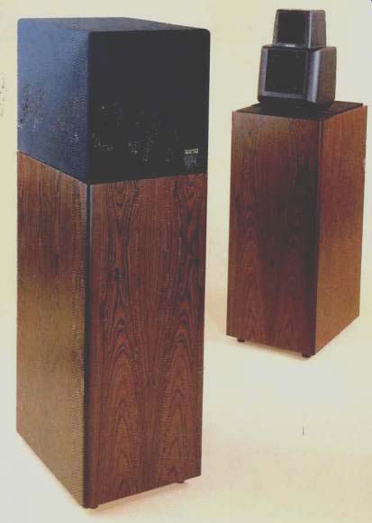
The KEF 107, the flagship model from KEF's "Reference Series" of loudspeakers, is primarily a high-end audiophile system. However, with its very high power-handling capacity, extended low-frequency response, and high maximum acoustic output capabilities, it will do justice to any type of program material from chamber music to hard rock. It represents the end result of many years of research and development and the pioneering use of computer-aided design and testing in the manufacture of loudspeakers and systems.
In early 1983, I had the pleasure of visiting the KEF plant in England, where I talked extensively with Laurie Fincham, KEF's technical director, and with KEF's founder and man aging director, Raymond Cooke (whose position is equivalent to that of president of an American firm). I came back very impressed with the company, its philosophy, and its products. When given the opportunity to review one of KEF's high-end speaker systems, I jumped at the chance.
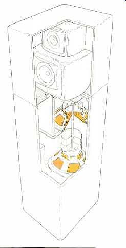
Fig. 1--Cutaway view of the KEF 107. Note the dual woofers, each firing
from a sealed enclosure into a shared, ducted cavity, and the rod connecting
the two woofer magnets. (See text.)
The KEF 107 is a three-way, modified direct-radiator system supplied with a line-level equalizer. The equalizer, called the KUBE (which stands for KEF User-variable Bass Equalizer), is used primarily to adjust the low-frequency characteristics of the system to the listening environment and also to equalize a moderate upper-midrange peak exhibited by the unequalized system. The equalizer is an integral part of the system design and not just an after-the-fact addition to add some extra sales appeal.
The two low-frequency drivers are mounted in a modified version of the vented-box enclosure, called a "coupled cavity configuration" by KEF. This type of cabinet provides a band-pass type of frequency response because the acoustic output from the enclosure comes only from the vent.
The mid and high frequencies are radiated from a separate high-frequency enclosure or head assembly that is mounted on top of the low-frequency enclosure. This separate enclosure, which also contains the midrange/tweeter crossover, is shaped to minimize mid- and high-frequency diffraction effects; this ensures smooth on- and off-axis frequency response. The head, which is detachable, is connected to the bass cabinet with a gold-plated XLR connector. The head assembly can be rotated roughly ±30° to optimize coverage of the listening area. This method of handling the mid and high frequencies continues a successful approach first offered in 1976 by KEF in the Model 105.
KEF uses "conjugate load matching" in the crossover so that the system's input impedance, over the range of 20 Hz to 20 kHz, is essentially resistive, with a value of about 4 ohms. This load is very easy for any amplifier to drive. The lower value of impedance essentially doubles the voltage sensitivity of the system and raises the acoustic output, as compared to an 8-ohm system.
While KEF does not specify crossover frequencies, measurements revealed that the system is crossed over at about 160 Hz and 3 kHz and that the respective drivers' acoustic outputs are essentially in phase at crossover, thus minimizing lobing error.
The highs are radiated by a ferrofluid-cooled dome tweeter. The tweeter is a refined version of KEF's T33 high-frequency unit, which is also used in other KEF systems.
The mid-frequencies are radiated by a polypropylene-cone midrange driver with an effective radiating diameter of about 4 inches (100 mm). This driver is an improved version of KEF's very fine 8110 midrange unit, with higher sensitivity and power handling. The mid-frequency driver is used down to the relatively low frequency of 160 Hz, because the band-pass vented-box low-frequency system will not easily go any higher in frequency. The wide range covered by the midrange driver (160 Hz to 3 kHz, over four octaves!) opens up the possibility of intermodulation of the upper-midrange frequencies by high-amplitude signals in the 150- to 300-Hz range.
The low frequencies, below 160 Hz, are generated by a special form of vented box called a band-pass vented-box enclosure. This modified form of vented-box cabinet differs from the standard vented box because all the sound generated is radiated from the vent only. No sound comes directly from the drivers because they are contained within the sealed-box enclosure. This enclosure has a band-pass type of frequency response that, unassisted, covers only a response of roughly one to two octaves. KEF's technical director, Laurie Fincham, completely described this type of system at the May 1979 Audio Engineering Society Convention in Los Angeles (Preprint 1512, D-4, "A Bandpass Loud speaker Enclosure"). Additional information can be found in a more recent paper by E. Geddes and D. Fawcett, "Band pass Loudspeaker Enclosures," which was presented at the November 1986 AES Convention in Los Angeles (Preprint 2383, D-3).
The band-pass vented-box enclosure offers several ad vantages and one major disadvantage. The major disadvantage is that its frequency response is limited to a relatively narrow range, about one to two octaves. This response range can be extended, of course, by the use of equalization, and this is what is done in the KEF 107. With the full amount of equalization, the effective range of the 107's low end extends from 20 to 150 Hz, a three-octave range.
The advantages of the band-pass style of vented-box enclosure include the following: First, because the sound is radiated only from the port, and not directly from the cone, all forms of distortion are potentially lower. This is due to the high linearity of the acoustic resonance system as compared to the mechanical resonance system of the cone driver. Second, the acoustic resonant system acts as an acoustic low-pass filter which attenuates any extraneous noises, such as distortion generated by the low-frequency driver. Third, the low-frequency response of the system rolls off at only 12 dB per octave, the same as a closed-box system, rather than the faster roll-off of a standard vented box, which is 24 dB per octave. This greatly increases the low-frequency energy below the system's 3-dB down point and also much improves the system's low-frequency transient response. Fourth, the sealed box loading one side of the cone adds additional stiffness to the driver and thus increases the system's subsonic power-handling capability.
This overcomes one of the major disadvantages of the standard vented-box enclosure, which essentially unloads the driver at frequencies below the vented-box resonance frequency.
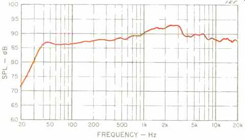
Fig. 2--On-axis frequency response without KUBE equalizer. (0 dB = 20 µPa.)
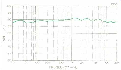
Fig.
3--On-axis frequency response with KUBE equalizer at factory-recommended
settings. Note extended bass and flattened midrange.
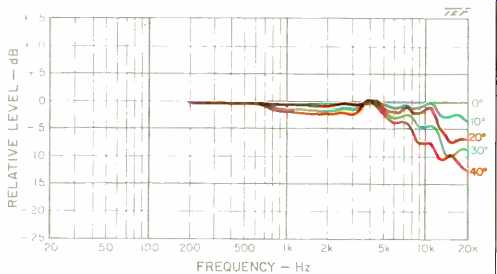
Fig. 4--Horizontal off-axis response, normalized to show deviations from
on-axis response.
The KEF 107 actually implements the band-pass vented box enclosure, using two low-frequency cone drivers. This configuration is shown in Fig. 1. The two drivers feed into a common cavity with a single duct exiting to the outside air.
Each driver is loaded by a separate sealed enclosure. The magnet assemblies of the two drivers are connected solidly together with a metal rod; this essentially cancels any inertial forces which could vibrate the cabinet. Additional distortion is cancelled due to the push-pull configuration of the drivers (one driver moves toward its frame while the other moves away).
The duct exit is actually on the top of the low-frequency enclosure, which places it in close proximity to the mid- and high-frequency drivers. Because the duct exit is significantly smaller than an equivalent direct-radiating cone assembly, the total radiating sound area for the whole 107 system is significantly smaller than for an equivalent system with the same acoustic output. The close proximity of low-, mid-, and high-frequency radiating elements in this system ensures more even coverage of the listening area. The frontal area of the system is quite close to that of a typical two-way mini-monitor, but with a vastly higher acoustic output capability that goes down into the response regions of some sub-woofers.
The KUBE equalizer is an active, line-level equalizer pro viding two types of equalization, one fixed, the other vari able. The fixed equalization compensates for mid- and high frequency response errors of the unequalized system and also provides a means for matching the left and right speakers of the stereo pair. The variable equalization allows control of the system's low-frequency output and response shape. Three parameters of the low-frequency response can be controlled "Extension," which allows setting of the lower cutoff of the system to 50, 35, 25, and 18 Hz; "Q," which allows setting of the low-frequency response shape continuously in the range from 0.3 (overdamped) to 0.7 (maximally flat), and "Contour," which allows setting of the overall low-frequency level below 500 Hz in the range of ±3 dB. These three controls allow a wide adjustment range of the system's low-frequency behavior so that response can be optimized for many different listening environments and types of program material.
The construction and finish of the 107 are of the very best quality. Much attention has been paid to detail, even in normally inaccessible areas. The system can be used with out the mid/high-frequency grille assembly without any apologies. The low-frequency and mid/high-frequency en closures are very solid and essentially inert due to very effective internal bracing and the special configuration of the cabinets. I was not aware of any cabinet wall vibration of any kind during my tests. Connections to the 107 are made via heavy-duty, gold-plated, knurled knob terminals de signed to accept large-diameter wire, 4-mm plugs, or spade connectors.
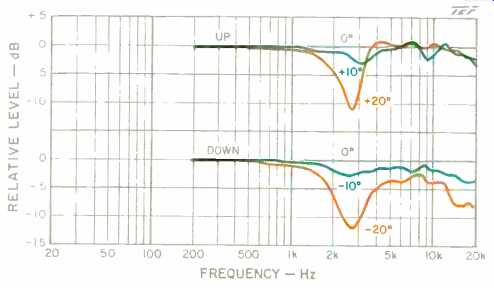
Fig. 5--Normalized vertical off-axis response for angles above the axis
(upper curves) and below it (lower curves).
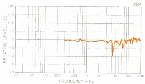
Fig. 6--Effect of grille on on-axis frequency response (normalized).
Measurements
Most of the measurements for this review were made with the Techron TEF System 12 analyzer, which uses the technique of Time Delay Spectrometry (TDS) invented by the late Richard Heyser. Mr. Heyser was the senior loudspeaker reviewer for Audio for more than a dozen years and used the TDS test technique extensively in his reviews.
TDS allows anechoic chamber-like, reflection-free measurements of parameters such as frequency response, phase response, and time response to be made under decidedly non-anechoic conditions. TDS measurements can be made under high noise-level conditions due to the inherent noise-rejection capabilities of the TDS technique.
The measurements in this review were generally done outdoors, with a combination of elevated free-field measurements, ground-plane measurements, and near-field measurements. Information on the ground-plane technique can be had in Mark Gander's paper in the Journal of the Audio Engineering Society ("Ground-Plane Acoustic Measurement of Loudspeaker Systems," Vol. 30, No. 10, p. 723, October 1982). My article on the near-field technique appeared in the April 1974 issue of the same journal ("Low-Frequency Loudspeaker Assessment by Nearfield Sound-Pressure Measurement," Vol. 22, No. 3, p. 154).
The system on-axis frequency response was measured at a distance of 2 meters directly on-axis of the tweeter. The input level was 2.83 V rms, which corresponds to a level of 1 watt into 8 ohms (the system is actually 4 ohms). The on-axis response was corrected to the standard distance of 1 meter for display of the data. The measurement parameters were set so that the data was essentially smoothed with a tenth-octave filter.
Figures 2 and 3, respectively, show the unequalized and equalized response curves of the system. The unequalized response is commendably smooth, exhibiting a lower 3-dB down point at about 35 Hz and actually extending beyond 20 kHz-out to 23 kHz-before dropping rapidly. An upper-midrange peak of about 3 dB, extending from 1 kHz to 3.5 kHz, is also noted. The sensitivity of the system appears to be roughly 89 dB for 2.83 V rms input. Remember that this is a measurement of boundary-free response similar to that measured in an anechoic chamber; the low-to-high frequency balance will change when the system is placed near reflective boundaries in an actual listening situation.
The equalized response curve was run with the factory recommended equalizer settings of full "Extension" (4), maximum Q (0.7), and a slight "Contour" boost ( + 1). With these equalizer settings, the response actually meets KEF's rating of 20 Hz to 20 kHz, ±2 dB! This is very flat indeed.
Note that the equalizer also nicely minimizes the upper-midrange response peak.
The off-axis frequency response was measured and is illustrated in Figs. 4 and 5. Figure 4 shows the normalized horizontal off-axis response plotted on a log frequency scale, but only for angles out to 40° off-axis. Normalization is equivalent to precisely equalizing the on-axis response flat and then measuring the off-axis response. The response does exhibit some high-frequency roll-off above 10 kHz at angles beyond 20°. Figure 5 shows the normalized vertical off-axis response for angles of 10° and 20° above and below the axis. An off-axis crossover dip is evident at about 3 kHz both for 20° up and for 20° down.
For critical listening, the listener should be within a 40° horizontal window centered on the axis of the system, and preferably within a 20° window, for accurate high-frequency response. Fortunately, the mid/high-frequency head module can be freely rotated horizontally to aim it at the preferred listening location.
Figure 6 shows the effect of the grille on the on-axis frequency response. The grille caused some narrow high-Q peaks and dips clue to internal reflections in the grille frame work. I suggest leaving it off for serious listening; the system does look quite handsome without it.
The on-axis response match between left and right was so close that it approached the repeatability limits of my test setup. The only significant difference occurred in the 9- to 14-kHz range, where the left speaker was slightly louder than the right speaker, about 1.5 dB. I judge this level of right/left matching to be extremely good. Subsequent measurements of the equalizer revealed no differences between its channels.
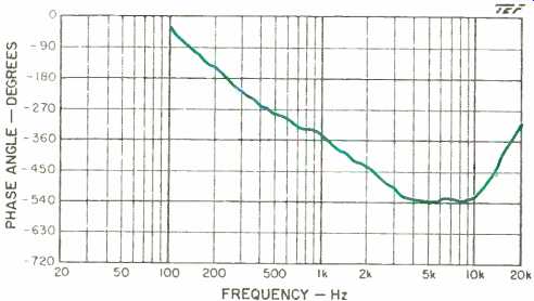
Fig. 7--On-axis phase response of the equalized system, with delay adjusted
for the tweeter.
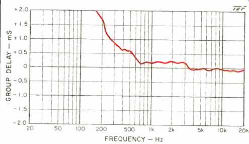
Fig. 8--Group delay corresponding to phase response of Fig. 7.
Figure 7 shows the phase response of the system (equalized) with the delay adjusted for the tweeter. Figure 8 shows the corresponding group-delay measurement. The group delay indicates that the midrange and tweeter arrival times differ by about 0.24 mS (240 uS), with the midrange lagging the tweeter. The increase in delay below 500 Hz reflects the normal minimum-phase delay caused by the high-pass characteristic of the speaker's response. Most available research indicates that this amount of mid/high-frequency all-pass (flat frequency response) delay is inaudible.
The on-axis energy-time response curve (ETC) of Fig. 9 is shown for a test signal swept over the range from 200 Hz to 10 kHz. In general, the ETC is very well behaved except for a broadening of the response at levels well down from the peak.
The measured impedance between 20 Hz and 20 kHz was so flat and well behaved that no test results need be displayed here. The impedance magnitude varied from a minimum of 3.8 ohms to a maximum of 4.6 ohms. The phase angle was less than 10° for all frequencies below 10 kHz and smoothly rose to roughly + 35° at 20 kHz. This means that the load can be considered as a resistor of about 4 ohms, which should be extremely easy for any amplifier to drive. Due to the constant nature of the load, no excessively high transient currents will be required by the load due to reactive effects. For speakers that have widely varying impedance, research has shown that with some program material, drive currents can sometimes reach values two to five times the values computed on the basis of minimum impedance alone. KEF points out that the 107 can actually be considered a typical 8-ohm system insofar as sensitivity and load are concerned.
Figures 10 through 13 show distortion measurements taken on the system. All measurements were made without the equalizer, using near-field techniques. Figure 10 shows harmonic distortion for the single frequency E, (41.7 Hz) at increasing power levels. Virtually no higher order harmonics are evident at higher powers. Figure 11 shows the inter modulation data for 250 Hz and 2 kHz. Moderate distortion is shown here because both frequencies are handled by the same driver. Figures 12 and 13 show swept second- and third-harmonic distortion at power levels corresponding to midband levels of 90 and 100 dB SPL at 1 meter. At an axial level of 100 dB in the bass range from 40 to 150 Hz, the distortion was essentially less than 1%. This is commendably low distortion at these levels. For the lower frequencies, the third harmonic predominated, while at higher frequencies, the second harmonic was greater.
To evaluate the maximum peak input and output capabilities of the loudspeaker, I used a peak-power test method similar to that used by KEF to evaluate their professional line of loudspeakers. These tests are very revealing in that they indicate, at each frequency, a system's short-term power-handling capacity and maximum acoustic output capabilities. The method, which uses a shaped tone-burst test signal, is discussed by S. Linkwitz in his JAES article in April 1980 (Vol. 28, No. 4, p. 250). This method allows the dynamic peak input and output power capabilities of the system to be evaluated over the complete audio range. The shaped tone burst restricts the energy of the burst to a relatively narrow 1/3-octave bandwidth. The burst lasts for 6.5 cycles and is shaped using the Hanning raised-cosine envelope.
This test signal has a good combination of characteristics that include short time duration, restricted frequency range, relatively high peak energy, and a waveform somewhat similar to actual musical waveforms.
The burst is presented at such a low duty cycle that the long-term thermal characteristics of the speaker under test are not exercised at all. In testing the 107, the tone burst was generated at 4 bursts per second, except at lower frequencies, where the repetition rate was lowered so as to maintain a crest factor (ratio of peak to average power) no lower than 20 dB. Note that typical crest factors of music, as recorded on Compact Discs, range from 15 to 25 dB.
The test method consists of evaluating the maximum peak input power-handling capacity and maximum output peak sound pressure levels at all the 1/3-octave center frequencies in the range from 20 Hz to 20 kHz. An extremely powerful amplifier, one which can generate 5,000 peak watts (141 V into a 4-ohm load), was used to drive the loudspeaker under test. (When I first started this project, I thought this amplifier would be plenty powerful enough for any test I would care to make. The measurements that follow showed me how wrong I was!)
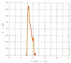
Fig. 9--One-meter on-axis ETC.
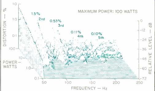
Fig. 10--Harmonic distortion products for a 41.7-Hz tone.
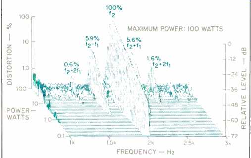
Fig. 11--Intermodulation distortion products for 250-Hz (f1) and 2-kHz (f2)
tones, mixed 1:1.
The test sequence consisted of determining how much of the special test signal could be handled by the speaker at each frequency before either the output sounded audibly distorted or distressed, or the acoustic output waveform appeared distorted on an oscilloscope monitoring the signal coming from a high-intensity microphone (whichever occurred first). At each frequency, the maximum peak input voltage and the corresponding generated peak output sound pressure level at 1 meter were recorded.
Figure 14 shows the maximum peak electrical input power-handling capacity of the loudspeaker. Except for a 2-dB limitation (625 watts) at 300 Hz, the system could handle peak power of 1 kilowatt and greater in the range from 50 Hz to 20 kHz. Above 5 kHz, the system could handle the full 5-kilowatt output of the amplifier (141 V peak)! In this range, amplifier clipping limited testing at higher power. Please realize that, during these tests, the system was producing some very loud sounds! After all this seemingly brutal power testing, the system did not seem to be affected in any way, as far as I could determine.
I found that at low frequencies, the 'scope waveform defined the power limit, while at higher frequencies, the audible effects defined the limits. I found that I was quite tolerant of rather high distortion levels (primarily second and third-harmonic distortion) at low frequencies but was very critical of any slight audible distortion at mid or high frequencies. Note that the 107's band-pass vented-box enclosure, fortunately, filters out most higher order low-frequency harmonics.
Figure 15 illustrates the maximum peak sound pressure levels the system generated at a distance of 1 meter, on axis, for the input levels shown in Fig. 14. Except for a limitation at and near 300 Hz, the system can generate peaks in excess of 115 dB SPL above 50 Hz. Above 1 kHz, the peak levels rise above 120 dB SPL! These levels are loud-hearing protection required! Also shown in Fig. 15 (dashed curve) are the maximum peak SPLs generated by a pair of 107s in my listening room, as measured at the listening location. The systems could generate peaks in excess of 110 dB SPL at frequencies above 30 Hz (100-dB peaks at 20 Hz). These are wall shaking levels! The room provides some 5 to 10 dB of low frequency gain, while a pair of speakers increases the level some 3 to 6 dB.
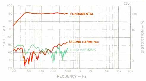
Fig. 12--Second- and third-harmonic distortion level vs. frequency for 90
dB SPL output at 1 meter on axis; input signal is 3.2 V rms (2.5 watts).
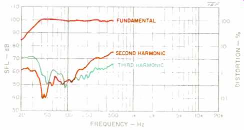
Fig. 13--Same as Fig. 12 but for 100 dB SPL at 1 meter on axis, using input
signal of 10 V rms (25 watts).
Please don't interpret this maximum input and output test data to mean that you should run right out and purchase a 2.5-kilowatt power amplifier with a peak power rating of 5 kilowatts to use with your KEF 107s. An amplifier of this size has the capability of blowing up any domestic loudspeaker if continuous long-term power in this range is presented to the system. What I am suggesting is that maybe we need an amplifier with an honest continuous rating of 100 to 200 watts and a peak power rating of 1 to 5 kilowatts (a dynamic headroom rating of 10 to 20 dB). This would allow you to play CDs with typical crest factors of 15 to 20 dB, without clipping, and to exercise the peak sound levels the system is capable of generating-your ears willing! I measured a wide variety of equalizer frequency responses at different control settings but have elected not to show them here because of space considerations as well as the complex nature of their interactions. Figure 16 shows the maximum boost and cut capabilities of the equalizer from 2 Hz to 1 kHz. Note the very high gain (20 to 25 dB) in the infrasonic range from 2 to 15 Hz. This could potentially cause amplifier-speaker overload problems and decreased headroom if any significant infrasonic program energy exists. Lower frequency measurements indicate a first-order roll-off of 6 dB per octave below about 1 Hz. The first production release of the KUBE was actually d.c.-coupled and exhibited problems with some power amplifiers. The current version is a.c.-coupled to minimize these problems.
One source of potential infrasonic energy is from turntable rumble, where tonearm resonances may generate frequencies in the 5- to 8-Hz range. This problem is compounded by the fact that previous measurements showed the speaker's maximum input level below 20 Hz to be only about 6 V rms before excessive distortion is generated. Since I have designed speaker systems, I can sympathize with some of the design goals that led to this high amount of gain, but at least an optional high-pass filter with a high roll-off rate could have been provided to roll off the subsonic frequencies when needed.
I measured the equalizer's maximum input and output voltage capabilities when its controls were set to their maximum boost settings ("Extension" = 4, Q = 0.7, "Contour" = +3). A standard 10-kilohm load was used for these measurements. Maximum voltage was considered to be the point where distortion of the output waveform became visible on an oscilloscope. The measurement (not shown) indicates that the lowest pass-band maximum output voltage was 3.5 V rms at about 2.5 kHz. Make sure you have your power-amplifier gain set high enough so that this limit is not reached by the equalizer. The measurement of maximum input voltage (also not shown) indicates a very low input limit of roughly 0.5 V rms for frequencies below about 15 Hz.
This low level is due to the high gain of the equalizer in this frequency range. If you use the maximum gain settings, be aware that you risk overloading the equalizer (and the speaker!) if levels above these limits are sent to the unit. A typical Compact Disc player can generate levels of 2 V rms down to below 2 Hz, so watch out!
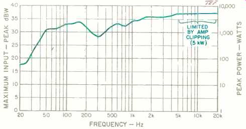
Fig. 14--Maximum peak input power for moderately clean output (see text).
Above about 5 kHz, note that limitations are imposed by clipping of a 5-kilowatt
amplifier, not by the speaker.
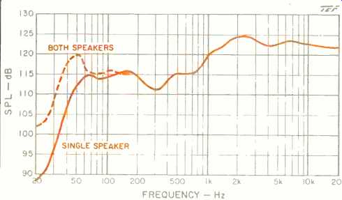
Fig.
15--Solid curve: Maximum peak SPL output at 1 meter, on axis, for input levels
shown in Fig. 14. Dashed curve: Combined output of two 107s measured at the
listening position, including low-frequency gain from room interactions.
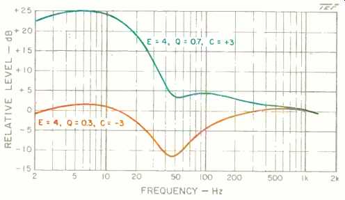
Fig. 16--Maximum boost and cut capabilities of KUBE equalizer supplied with
the 107. Note the high gain in the infrasonic region, below 15 Hz (see text).
Use and Listening Tests
Listening tests were conducted primarily in my basement listening room. The room is somewhat small, with a volume of about 1,500 cubic feet (43 cubic meters). The walls are all non-parallel (by accident, not by design). The systems were placed 20 inches (0.5 meter) away from the wall and separated by about 8 feet (2.5 meters). The upper-frequency modules were aimed at the listening position on the couch along the opposite wall. My ears were at the same height as the tweeters when I was seated on the couch.
A good portion of the listening tests was actually done without the equalizer, not because I have an aversion to equalizers but only because the system sounded quite good without it. The upper-midrange peak at 2 kHz is quite moderate and was audible only when the program material contained energy in its range. I had to listen critically to the midrange frequencies to hear the effect of the equalizer being switched in and out.
It is always a good exercise to listen to a specific amount of spectral aberration being switched in and out of a signal path, to calibrate your ears to the audible effects of certain spectral shifts. The KEF equalizer is quite good for providing specific low-frequency adjustments to allow you to listen to the effects. It's quite easy, for example, to change the Q of the low-frequency roll-off from 0.3 to 0.7 to see how audible the change is. In most situations, the effect is quite subtle.
Several times, I found myself going up to the equalizer and twisting the controls back and forth to see if it was operating, and then doing a double take because it didn't seem to make much difference. The program material must have frequency content in the equalizer's adjustment range for you to hear the equalizer's effect.
Most of my equalizer-in-the-circuit listening was done with the factory-recommended settings of "Extension" = 4 (flat to 20 Hz), Q = 0.7, and "Contour" = + 1. With the equalizer in the signal path, the system provided a very neutral listening environment, with no emphasis or de-emphasis of any part of the frequency range. Imaging was very stable and consistent. Reproduction of male singing voice with acoustic guitar was very accurate and realistic. Female vocals showed no hint of spectral imbalance. Because of the very close right/left matching of the speakers, there was absolutely no lateral shift of image with changing frequency. I was aware of some moderate roll-off of the extreme high frequencies at relatively large off-axis angles. Make sure that the high-frequency modules are aimed at the listening position to minimize this effect.
I initially was somewhat apprehensive about using the equalizer at settings near full boost, because of the amount of boost I knew it could provide. Subsequent listening proved that my worries were unfounded, however. At only one time was I aware of any overload problems I could attribute directly to the equalizer: The cannon shots on Telarc's CD of Tchaikovsky's "1812 Overture." I suggest you make sure your power amp's input gain settings are set high so that the drive level to the equalizer is kept low. If you use the equalizer in the tape loop of a receiver, you could be in trouble because the full signal at the AUX input is typically fed through to the tape out, with no attenuation. This means that the full 2 V rms output (at 0-dB record level) of your CD player may be applied directly to the equalizer. If your player has adjustable outputs, use them to reduce the drive level to the equalizer.
The low-frequency response was always quite solid and very much in evidence when the program material demanded it. Pipe-organ pedal notes were reproduced with much authority. The low frequencies could get up to very impressive sound levels without any audible stress whatsoever. On transient bass passages, such as rock kick drum, the lows were very tight and could be turned up to levels that would make a professional drummer happy. The extended low frequency response of the system unearthed some very low-frequency rumble, of which I was previously not aware, on a couple of my classical Compact Discs.
With three teenagers in my house, our listening system is subjected to many varied types of program material, from Mozart and Dave Grusin to ZZ Top and Run-D.M.C. The KEFs proved themselves very versatile in realistically reproducing everything from the subtleties of chamber music and delicate female vocals, played at low to moderate levels, to heavy-metal rock music, played at gut-thumping levels that only my teenage son could appreciate.
There are not too many systems that can do justice to such extremes in program material and not come out as a middle-of-the-road compromise. The KEFs did an extremely good job on all types of program material. The 107s are a fine example of a system that provides a good combination of physical size, high maximum output capability, very smooth response, and high power-handling capacity. In the true sense of the term, the KEF 107s can be considered a reference standard.
--D. B. Keele, Jr.
D. B. Keele, Jr. is Manager of Software Development for the Techron Industrial Products Division of Crown International, Inc., makers of TEF measurement equipment on which the tests for this review were performed. Don Keele is a Fellow of the Audio Engineering Society, so honored for his work on vented box design, and helped develop the near-field woofer measurement technique. He has also worked at Electro-Voice, Klipsch, and JBL. He says that he is most proud of his design work on constant-directivity horns, an area where he holds three patents.
(adapted from Audio magazine, Feb. 1988)
Also see:
Tannoy 615 Speaker (Aug. 1992)
Klipschorn Loudspeaker (Nov. 1986)
Altec Lansing 511 Speaker (Apr. 1991)
= = = =