Manufacturer's Specifications:
System Type: Four-way system with vented, coupled-cavity enclosure and optional KUBE external active equalizer.
Drivers: Two 8-in. (200-mm) cone woofers, two 6 1/2-in. (165-mm) polypropylene cone low/midrange drivers, and 6 1/2-in. (165-mm) coincident-source drive unit with 1-in. (25.4-mm) polyamide soft-dome tweeter.
Frequency Response: 49 Hz to 20 kHz, ±2.5 dB, at 2 meters on reference axis.
Directional Characteristics: Flat within 2 dB from 50 Hz to 17 kHz up to 30° off axis.
Sensitivity: 93 dB SPL at 1 meter, for pink-noise input of 2.83 V rms, band-limited from 50 Hz to 20 kHz.
Maximum Output: 115 dB SPL on program peaks under typical listening conditions.
Crossover Frequencies: 150 Hz, 350 Hz, and 2.3 kHz.
Impedance: 4 ohms, resistive, from 20 Hz to 20 kHz.
Recommended Amplifier Power: 50 to 300 watts per channel.
Dimensions: 431/2 in. H x 11 in. W x 16 in. D (110.4 cm x 28 cm x 40.5 cm).
Weight: 92.5 lbs. (42 kg). Price: $3,900 per pair, in black ash, rosewood, or walnut veneer; KUBE 200 equalizer, $400.
Company Address: KEF Electronics of America, 14120-K Sullyfield Circle, Chantilly, Va. 22021.
------------------
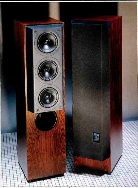
KEF, a British company, has been in the forefront of applying the most modern loudspeaker technology. In the Reference Series Model 105/3, KEF has taken advantage of the latest in very powerful neodymium-iron-boron magnets to shrink a 1-inch dome tweeter and actually place it in the neck of a midrange cone loudspeaker. The 105/3 is the first of KEF's Reference Series high-end line to use the new "coincident source," coaxial-style, mid-high frequency driver, which they have dubbed the "Uni-Q." Previously, only a lower cost line of KEF loudspeakers utilized this technology.
The 105/3 is a floor-standing, four-way system that uses the Uni-Q 6 1/2-inch coaxial driver to reproduce all the frequencies above 350 Hz. The lower frequencies, up to 150 Hz, are generated by two 8-inch cone woofers in KEF's "coupled cavity" bass-loading system. This is a form of single-tuned, bandpass vented-box enclosure design that KEF has used in several previous systems, including the Model 107 (reviewed in the February 1988 issue). Each woofer operates in its own sealed enclosure and is coupled to a third port-tuned, central enclosure which radiates bass energy into the room through its port. The two woofers are joined through the centers of their magnet structures by a heavy metal rod, which effectively cancels the opposing reactive motions of their frames. This helps minimize sonic coloration caused by unwanted box vibration triggered by driver reactive forces.
The remaining frequency range, between the bass section and the Uni-Q coaxial driver, is reproduced by two additional 6 1/2-inch cone drivers symmetrically, placed above and below the Uni-Q driver. This configuration provides a symmetrical, forward-facing, vertical coverage pattern that has no lobing error (i.e., its vertical directional pattern stays solidly aimed in the forward direction at all frequencies through crossover). KEF has chosen a relatively low crossover frequency of 350 Hz between the lower mids and Uni-Q coaxial driver, which effectively minimizes any additional lobing and beaming due to the relatively wide spacing of the midrange drivers. The two lower midrange drivers have the effective area of a much larger driver but the width of a small driver. This allows a narrow front panel that improves lateral imaging and reduces baffle-reflection and diffraction problems.
KEF makes extensive use of conjugate load matching to smooth the system's impedance, thus making it a much better load for amplifiers and their associated connecting cables. À system with a purely resistive impedance, independent of frequency, is a very easy load to drive. It is also very tolerant of high values of cable resistance that typically cause frequency response variations in speaker systems whose impedance varies with frequency. For a system with purely resistive impedance, the cable resistance causes only a reduction in power available to the loudspeaker, not any frequency response variations.
The Uni-Q driver is superficially much like a typical coaxial loudspeaker, but the tweeter is actually mounted at the apex of the midrange driver's cone, inside the midrange voice-coil instead of in front of the larger driver's cone. The latter technique offsets the acoustic centers of the individual drive units. The Uni-Q was designed to align the acoustic centers of the drive units (the points where the waves appear to originate) so that their individual directional patterns will match very closely through the crossover region.
This would effectively provide a two-way driver that would behave as a single coherent source of sound, providing uniform coverage over a wide but controlled region.
This concept was originally implemented in the distant past with horn-loaded high-frequency drivers, where the high-frequency sound actually passed through the center of the low-frequency cone driver and was radiated by a horn mounted in the center of the bass device. The old Altec Lansing 604 coaxial was just such a system, and utilized a 15-inch woofer and multicellular horn tweeter. These coaxes are still living in the professional market, where systems such as the UREI 813 control room monitor (with updated horn) are still used quite extensively. The U.K.'s Tannoy has several good horn-loaded coaxial systems in its current line of speakers.
KEF's Uni-Q assembly extends the concept to a completely direct-radiator design utilizing a well-behaved dome tweeter with a very small, high-energy magnet, mounted in the center of a 61/2-inch midrange driver. The cone of the midrange driver actually acts as a waveguide for the high frequencies, and thus potentially matches the high- and low-frequency coverage patterns of the individual drivers.
The 105/3 is designed to have wide but controlled coverage that improves its imaging capabilities by minimizing wall, floor, and ceiling reflections.
This model also follows KEF's established system of computer-matching all speaker and crossover components to minimize unit-to-unit variations. KEF tests all incoming components and numbers them according to their measured values; KEF schematics then either specify particular part values or show tables for the component combinations to meet the company's very tight specifications.
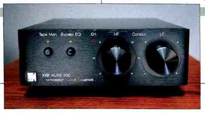
The 105/3 can be used with the KUBE 200 external active equalizer, which extends the response of the system down to 20 Hz and also compensates for response variations caused by speaker placement and listening room acoustics. The equalizer has two "Contour" controls, "HF" and "LF," which provide limited-range adjustment of high- and low-frequency level. The equalizer also contains a front-panel EQ bypass switch and complete tape monitor switching capabilities. In addition, the rear panel contains equalized and nonequalized outputs (one set with level control)
that allow versatile interconnection and level adjustment in a biamplified system and also provide convenient capabilities for multi-room or audio/video systems.
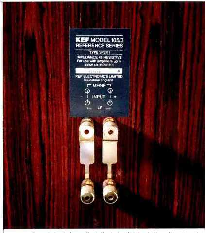
Twin sets of gold-plated terminals on each speaker's rear panel, spaced 3/4 inch (19 mm) apart, allow bi-wiring or biamping. Removable, gold-plated connecting straps are installed at the factory for normal single-cable drive. The terminal can handle large cables up to about 0.25 inch (6.3 mm) in diameter. Unlike some high-end systems I have reviewed, the KEF has easily accessible terminals so that I could get my fingers on their knurled knobs to tighten them securely.
Separate p.c. boards hold the high- and low-frequency sections of the crossover, but both are mounted in the woofer enclosure. The crossover is composed of 51 separate components, divided up into 15 resistors, 13 inductors, and 23 capacitors. All component quality is first-rate.
The enclosure is very substantial and well strengthened by the construction of the internal woofer-mounting compartments and additional bracing. The two midrange drivers and the Uni-Q high-frequency drive unit are mounted on an independent, specially profiled module, precision-machined from solid medium-density fiberboard, 3 inches thick. This mid/high-frequency module holds a vertically symmetrical array of three sealed sub-enclosures, made of die-cast aluminum, behind the drivers. The module, with drivers attached, is mounted to the front of the enclosure by four respectable, 5/16-inch socket-head bolts, 3 inches long.
The module actually protrudes about 3 inches beyond the front of the woofer enclosure, making the system look front-heavy with its grille off. The smoothly contoured port outlet for the central resonant-air chamber is mounted just below the module.
The woofer enclosure is finished on all five sides in rosewood, walnut, or black ash veneer. The sculptured grille assembly covers the top seven-eighths of the front of the enclosure and is secured to the cabinet with four powerful disk magnets. (And they are powerful! You had better keep your fingertips from between the grille and cabinet when replacing the grille assembly, or you'll get pinched when the grille snaps into place!) The grille itself is contoured to fit snugly over the mid/high module and provides no added sharp edges to diffract the high-frequency sound.
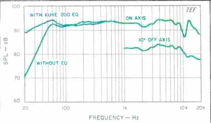
Fig. 1-Equivalent 1-meter frequency response.
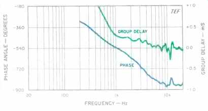
Fig. 2-Phase angle and group delay.
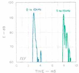
Fig. 3-On-axis energy/ time curves over standard range (left) and centered
over tweeter range (right). Tweeter ETC has been shifted right by 5 mS, for
clarity; see text.
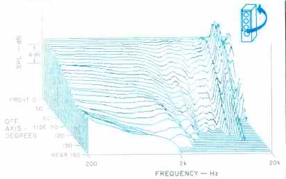
Fig. 4-Horizontal off-axis response, normalized to the on-axis response;
see text.
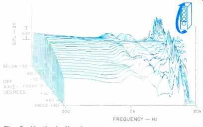
Fig. 5-Vertical off-axis response, normalized to the on-axis response; see
text.
Measurements
The performance of the 105/3s was evaluated by measuring several properties including: On- and off-axis frequency responses, energy-versus-time behavior, impedance versus frequency, harmonic and IM distortion, and maximum peak input and output capabilities. A few frequency response measurements were also run on the KUBE 200 active equalizer. The systems were evaluated using ground plane, near-field, and elevated free-field methods. Evaluation equipment consisted of a Techron TEF System 12 Plus Time Delay Spectrometry (TDS) analyzer, a B & K 4007 condenser microphone, Crown power amplifiers, and Leader signal generators, attenuators, voltmeter, and oscilloscope.
The 1-meter on-axis frequency response curve, with and without the KUBE 200, is shown in Fig. 1, smoothed with a tenth-octave filter. The effects of the grille are not shown because it caused less than ± 1 dB change in the curve.
The curve was taken at 2 meters, 36 inches up, normal to the enclosure. This position is on a line toward the ear position of a listener seated 3 meters away and is about 2° above the axis of the tweeter. All the following measurements were also taken with the grille off.
Without equalization, the curve fits within a ±3.5 dB window from 44 Hz to 20 kHz, limited only by a moderately high-Q dip and peak between 10 and 15 kHz. With the KUBE 200's 18-dB lift at 20 Hz, the low-frequency response is extended down to 20 Hz. With equalization, the curve fits within a much tighter ±2 dB envelope from 24 Hz to 10 kHz.
Subsequent measurements revealed that the response roughness above 10 kHz was confined to a cone roughly 7° around the axis. The curve at 10° off the horizontal axis exhibits much smoother high-frequency behavior.
The 1-meter, 2.83-V rms sensitivity was determined by averaging the axial response from 250 Hz to 4 kHz. This yielded an unusually high sensitivity of 93.5 dB SPL! The right/left matching of the systems was quite good, with no more than ± 1 dB variation above 100 Hz.
Figure 2 displays the axial phase and group-delay measurements of the system, corrected for the tweeter's time arrival. The phase response (lower curve) exhibits a total phase rotation of about 325° between 1 and 20 kHz. A separate measurement of offset revealed that the Uni-Q's midrange trails its tweeter by about 0.21 mS (210µS), which corresponds to a distance of 2.8 inches (72 mm). At the crossover of 2.3 kHz, this offset represents approximately one-half wavelength, or about 180°. Note that the top of the phase graph is not at 0° but at-180°; this is due to the additional phase lag that results from the low-frequency drivers' being mounted inside the box, and hence farther away, as compared to their being mounted on the enclosure's front surface.
The energy/time curve (ETC) is shown in the left-hand curve of Fig. 3, for a test signal swept over the range of 200 Hz to 10 kHz. This ETC represents mostly the tweeter's response and emphasizes energy from 2 to 9 kHz. The response is quite tight and is followed only by one arrival more than 24 dB down.
A second ETC sweep was run from 5 to 15 kHz, covering only the tweeter's range, to investigate the high-frequency problems seen earlier. The right-hand curve of Fig. 3 shows two closely spaced secondary arrivals delayed by 204 and 561 µS at levels of-7.6 and-12.6 dB corresponding to distances of 2.75 and 7.58 inches, respectively. To generate a dip at 11 kHz would take an in-phase signal delayed by one-half period, about 45 µS, which corresponds to a distance of about 0.6 inch. Because the measured times were much greater than this calculated value, I am at a loss to explain the significance of the second ETC measurement.
Apparently there is a high-frequency reflection of the tweeter's output, possibly off the Uni-Q's midrange cone, with a delay of about 45 µS that causes the 11-kHz dip.
A high-level, low-frequency sine-wave sweep did not reveal any enclosure side-wall vibrations; the walls were quite rigid and unmoving. There was, however, some vibration of the mid/high module against the front of the woofer enclosure, which seemed to be eliminated by tightening the bolts holding the module to the panel. No wind noises were evident from the port at high levels when driven at and near the box tuning frequency (55 to 65 Hz). The lower woofer, which could be viewed through the port with the system's grille off, had roughly constant excursion up to 50 Hz, decreasing by about 50% at 60 Hz, and reaching a minimum at about 65 Hz (the box tuning, apparently). The bottom woofer exhibited no dynamic offset that I could determine.
The normalized horizontal "3-D" off-axis curves of the 105/3 are shown in Fig. 4. The curves are very well behaved except for off-axis high-frequency roughness above 10 kHz. Because the on-axis high-frequency response is rough but the off-axis response is not, the normalization process actually transfers the on-axis roughness to all the off-axis curves. This implies that the on-axis high-frequency response should not be equalized flat, which would effectively make the response flat on axis at the expense of the response at all the off-axis directions.
The vertical off-axis curves, shown in Fig. 5, are actually quite similar to the horizontal curves but with some low-frequency fluctuations. Note the absence of sharp dips in the crossover region that typically occur with other systems due to spatially separated mid- and high-frequency drivers.
The same apparent off-axis high-frequency roughness is evident in these curves due to the normalization process, as noted before.
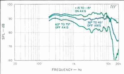
Fig. 6-Mean horizontal responses derived from data of Fig. 4.
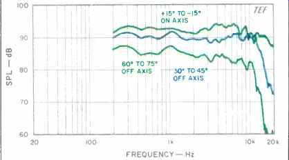
Fig. 7-Mean vertical responses derived from data of Fig. 5.
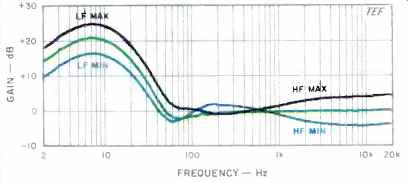
Fig. 8-Frequency response of KUBE 200 equalizer at different control settings.
Figures 6 and 7 were derived from the previous "3-D" data by calculating response mean averages of several adjacent curves in specific on- and off-axis angular regions.
Figure 6 shows the horizontal curves of the 105/3. The curve within ± 15° of the axis horizontally is quite smooth and extended except for a roll-off above 9 kHz and a slight dip at 11 kHz. The effects of the localized on-axis roughness, noted previously between 10 and 15 kHz, are minimized as a result of the spatial averaging. The 30° to 45° response is also quite smooth and extended but exhibits a rapid high-frequency roll-off above 12 kHz. The 60° to 75° off-axis averaged response exhibits a lowered plateau above 2 kHz, with minimal response anomalies, also coupled with a rapid high-frequency roll-off above 12 kHz. The uniformity of these curves indicates that the lateral imaging of the 105/3s should be quite good.
The mean vertical responses in Fig. 7 may make you do a double take after viewing the horizontal curves. The vertical and horizontal off-axis mean curves are virtually the same except for increased directivity below 1.5 kHz due to the system's greater size in the vertical dimension. There is absolutely no sign of the peaks or dips in the crossover region typically found in systems with spatially separated mid- and high-frequency radiators. The coaxial-style coincident mid/high-frequency driver really does work! The extreme uniformity of both the horizontal and vertical off-axis curves and the relatively high directivity of the 105/3's radiation pattern indicate that the imaging and soundstaging of the system should be excellent and minimally affected by listening room acoustical conditions.
Figure 8 shows the frequency response curves of the KUBE 200 active equalizer from 2 Hz to 20 kHz. Curves were run with the "LF" and "HF" controls in their minimum, detent (mid), and maximum positions. The measurements confirm that both controls provide an adjustment range of approximately-6 to +4 dB. The "LF" control mainly affects the range below 150 Hz, while the "HF" control adjusts the range above 500 Hz. The output of the equalizer clipped at about ± 17 V d.c. with no load.
Note that with the "LF" control in its maximum position, there is a very high boost, of 20 to 24 dB, in the infrasonic range from 2 to 15 Hz! This could potentially cause amplifier/speaker overload problems, and decreased headroom, if any significant infrasonic program energy exists. Because one potential source of infrasonic energy is from turntable rumble (with the possibility of associated tonearm resonances), be aware of possible problems if you play LPs with the KUBE equalizer at this setting! Compact Discs, however, do not generate subsonic signals except for those deliberately recorded. Fortunately, below approximately 3 Hz, the response is rolled off at a 6-dB/octave rate. Measurements indicated that with the "LF" control at maximum boost, input voltage at subsonic frequencies from 5 to 15 Hz must be limited to a maximum of about 0.75 V rms, to prevent output clipping.
Figure 9 shows the 105/3's impedance from 20 Hz to 20 kHz. The average impedance is closer to 3 ohms rather than to the rated 4 ohms. A maximum of only 5.8 ohms and a significantly low minimum of 2.4 ohms were reached in the power-heavy bass range, at 40 and 65 Hz, respectively.
Even though KEF went to great lengths to even out the system's impedance variations, its low minimum impedance of 2.4 ohms, coupled with its remaining variation of 2.4 x , make the 105/3s still quite sensitive to cable resistance. To keep cable-drop effects from causing peaks and dips in response greater than 0.1 dB, cable series resistance must be limited to a (low) maximum of 0.050 ohm (50 milliohms)! Although the 105/3's load impedance is not much higher than the very low measured impedance of the Thiel CS5, reviewed in the February 1991 issue, the KEF's power demand is much lower due to its much greater sensitivity.
As with the Thiel CS5s, the low impedance of the 105/3s makes them a demanding load on the power amplifier. Only amplifiers that can supply large currents into low impedances should be used with this speaker and should be hooked up only with short lengths of low-resistance cable.
Figure 10 shows the complex impedance, over the range from 5 Hz to 29 kHz. Note that the horizontal and vertical scales only cover a range of 6 ohms. If the impedance were compensated exactly so that the system, had an impedance of 4 ohms at all frequencies, this plot would be a dot on the horizontal axis at a resistance of 4 ohms, with a reactive part of zero. The phase angle of the impedance (not shown) reached a maximum of + 24° at 1.4 kHz and a minimum of 42° at 51 Hz.
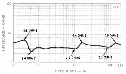
Fig. 9-Magnitude of impedance vs. frequency.
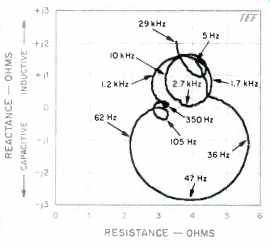
Fig. 10-Complex impedance, showing reactance and resistance vs. frequency.
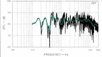
Fig. 11-Three-meter room response, showing both raw and smoothed data.
The 3-meter room curve of the system, with both raw and sixth-octave smoothed responses, is shown in Fig. 11. The 105/3 was in the right stereo position, aimed at the listening location, and the test microphone was placed at ear height (36 inches), at the listener position. The KUBE 200 equalizer was not used for this test. The system was swept from 100 Hz to 20 kHz with a 2.83-V rms sine-wave signal, corresponding to 2 watts into the rated 4-ohm load. Note that the system is generating a loud 83 to 84 dB average SPL, as compared to the 75 to 80 dB range of most other systems.
The parameters of the TDS sweep were chosen so that the direct sound and first 13 mS of the room's reverberation were included. The curve is very well behaved and extended, except for some roughness between 200 Hz and 1 kHz.
Above 2 kHz, the curve is quite smooth but exhibits some high-frequency roll-off above 10 kHz.
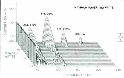
Fig. 12-Harmonic distortion products for the musical tone E1 (41.2 Hz).
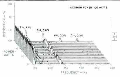
Fig. 13-Harmonic distortion products for the musical tone A2 (110 Hz).
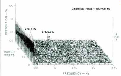
Fig. 14-Harmonic distortion products for the musical tone A4 (440 Hz).
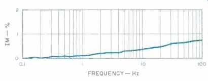
Fig. 15-IM distortion on 440 Hz (A4) produced by 41.2 Hz (E1) when mixed
in one-to-one proportion.
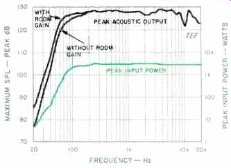
Fig. 16-Maximum peak sound output, measured at 1 meter on axis, and corresponding
maximum peak input power levels.
Figures 12, 13, and 14 show harmonic distortion spectra versus power level for the musical notes of E, (41.2 Hz), A2 (110 Hz), and A4 (440 Hz). These measurements indicate the harmonic distortion generated with the application of power levels from 0.1 to 100 watts (-10 to 20 dBW, a 30-dB dynamic range) in 1-dB steps. The power levels were computed using the rated system impedance of 4 ohms, for which 20 V rms would nominally equal 100 watts.
Figure 12 shows that for E1 (41.2 Hz), the second and third harmonics predominate at lower power levels, while at higher power levels, the fourth and fifth harmonics make themselves evident. The third harmonic reaches a substantial 29% at full power, which indicates a symmetrical two-sided nonlinearity, most likely the low-frequency drivers reaching their excursion limits at high amplitudes. The second, fourth, and fifth harmonics reach only 4.5%, 2.2%, and 1% at full power. Although the distortion is quite high, note that the system is generating a loud 103 dB SPL at 1 meter with full power at 41.2 Hz. Note also the very low level of higher order harmonics at full power, a direct result of the low-frequency enclosure's bandpass vented-box design, which acoustically filters out the higher order harmonics.
The A2 (110-Hz) harmonic data is shown in Fig. 13. The graph shows that only the second and third harmonics were significant over the tested power range, with the second harmonic predominating at higher power levels. The second harmonic reached a level of only 1.1% at full power, while the higher order harmonics reached only 0.6% or less at full power. Realize that at 110 Hz the system is generating a very loud 110 dB SPL at 100 watts! I first tried the system at full power with a 110-Hz sine wave in my listening room, which caused massive sympathetic vibration of all loose objects in the room; a couple of knickknacks actually came off the walls! The A4 (440-Hz) harmonic measurements are shown in Fig. 14. The only measurable distortion at full power was a low amount of second harmonic, which peaked at about 1.1% and only 0.6% of third harmonic. All other distortion products were below the noise floor of the display! The IM on a 440-Hz (A4) tone, created by mixing with a 41.2-Hz (E1) tone of equal input power, is shown in Fig. 15.
The IM distortion gradually rises with power, reaching only 0.8% at full power. This is a very low value, one of the lowest I've measured. The first-order (f2 ± ft) and second-order (f2 ± 2f1) side frequencies were the only significant ones in this power range. The design of the 105/3, which places two crossover points below 440 Hz, minimizes IM distortion because the two test tones are channeled to two different drivers.
The maximum peak input power-handling capacity of the 105/3 is shown in the lower curve of Fig. 16. Below 20 Hz (not shown), the peak input power was limited to about 8 watts to avoid severe distortion. Above 20 Hz, the input power rises rapidly with frequency up to about 125 Hz, where the test power amplifier started to clip at about 2.5 kW nominal (100 V peak into the rated 4-ohm load, although the measured impedance was actually closer to 3 ohms). At this and all higher frequencies, the power amplifier's clip limit was reached before the speaker reached its limit! The upper curve in Fig. 16 shows the maximum peak sound pressure levels the system can generate at a distance of 1 meter on axis for the input levels shown in the lower curve. Also shown on the upper curve is the room gain of a typical listening room at low frequencies. This adds about 3 dB to the response at 80 Hz and 9 dB at 20 Hz. The peak acoustic output rises very rapidly with frequency up to 125 Hz, where the power amplifier limits the output. With room gain, a single 105/3 can generate peaks in excess of 110 dB SPL above 45 Hz and greater than 120 dB above 55 Hz. With or without room gain, the low-frequency output of a single system rolls off very rapidly with frequency; even with room gain, it drops to only about 86 dB SPL at 20 Hz. A pair of these systems playing mono bass will be able to generate levels some 3 to 6 dB higher. Above 100 Hz, the systems can generate whopping peak levels in excess of 126 dB! The high power-handling capacity of the systems, coupled with their high sensitivity, allows them to be played very loud indeed.
Use and Listening Tests
I listened to the KEF 105/3s in my listening room, which is furnished in normal living-room style with a carpeted floor and is approximately 15v2 x 27 x 8 feet. Driving equipment included Rotel RCD-855 and Onkyo Grand Integra DX-G10 CD players, a Krell KSP-7B preamp, a Krell KSA200B solid-state power amplifier, and Straight Wire Maestro interconnects and speaker cables. I did about half of the listening before the measurements were made.
All of the listening was done with the 105/3s placed in my customary evaluation position, about 6 feet away from the short rear wall, and separated by 8 feet. The speakers were about 4 feet from the side walls. The first round of listening was done with the systems toed in and aimed directly at my head. Later listening was done with them cross-fired at a 100 angle. The measurements indicated that this cross-firing would significantly smooth out the system's top-octave response. I listened sitting on the sofa about 10 feet away, which placed my ears about 36 inches above the floor.
The systems were hooked up in a normal single-cable configuration, not bi-wired. At nearly 100 pounds apiece, the systems are quite heavy, but one person can move them by tipping them slightly and walking them on two of the enclosure's feet. If the grille is off, a strong person can lift the systems by placing one arm under the exposed mid/ high module and the other in the rear.
The KUBE 200 equalizer was used in the tape loop of the Krell preamplifier. A lot of my listening was done with the equalizer switched out. When it was switched in, I left the "HF" control in the flat position, though I did experiment with the "LF" adjustment. Switched in, the equalizer added a needed low-frequency heft or weight to most program material. However, if the program had any significant high-level material below 50 Hz, and was played loud, the equalizer's boost would often make the low frequencies sound mushy and distorted because of speaker overload.
When I first sat down to listen to the 105/3s, I placed a favorite orchestral CD in the player, turned the volume up to my usual level, hit the play button, and was promptly blown away by the volume. The KEFs are fully 6 to 10 dB more sensitive than the typical systems I listen to; the volume levels generated by typical speakers with your usual 200-watt amplifier can be generated by these KEFs with an amplifier of only 20 to 50 watts.
I was initially very impressed by the neutral character, precise imaging, and extremely even coverage of the KEF 105/3s. These impressions have not diminished after longer listening. The high peak output capability of the systems much improves their impact and realism in reproducing transient sounds that require high peak sound levels, such as drum rim shots, explosive sound effects (à la Ein Strauss-fest, Telarc CD-80098), and other program material with high peak levels. When played at realistic levels, the high sensitivity and power handling of the 105/3s directly translate into the ability to reproduce peak levels that closely match those of live sound, thus improving realism. Some digitally recorded jazz has crest factors approaching 30 dB, which makes it very hard to reproduce at realistic average levels without peak clipping. (Track 5 of the Flim and the BB's album TriCycle, DMP CD-443, has a measured crest factor of 29.9 dB!) If two speaker systems are compared with the same power amplifier and at the same realistic average sound level, the system with the higher sensitivity will reproduce higher peak levels. This is directly due to increased power amplifier headroom when driving the more sensitive system (assuming that the amplifier, when driving the low-sensitivity system, is being driven hard enough to cause significant clipping). I was very impressed with the 105/3s' handling of the sharp, intense transient sounds and very distinct lateral imaging of the computer-synthesized plucked string sounds on track 14, "Silicon Valley Breakdown," on The Digital Domain CD (Elektra 9 60303-2). It is a great demo disc for imaging, dynamic range, and sound effects. The Huey helicopter sequence on track 16 could be played at very realistic levels. Due to high-level low frequencies on this track, it sounded much more realistic with the EQ switched out; when the equalizer was switched in, headroom suffered greatly. When played at highest level before audible distortion, the 105/3s produced sound levels of 92 dBA (105 dBC) with the EQ in and 99 dBA (109 dBC) when it was switched out. As long as we are talking sound effects, the 105/3s did an incredibly hair-raising rendition of the USAF F-16 fighter jet flyovers on track 3 of the Sonic Booms CD (Bainbridge BCD6276): 110 dBA, or 112 dBC, without the EQ. Great fun! Now on to more serious listening .. On the Winds of War and Peace CD of Lowell Graham conducting the National Symphonic Winds (Wilson Audiophile WCD-8823), the systems rendered the massed horns very cleanly and sounded excellent on the bass underpinning and snare drums on track 6. On Pat Coil's Steps (Sheffield Lab CD-31), the vocals, string bass, and particularly the strings on track 7 were reproduced effortlessly without any harsh or strident effects. Quite thrilling were the dynamics of John Arpin's playing of Louis Gottschalk's pre-ragtime piano compositions on Cakewalk (ProArte Digital CDD 515). The 105/3s passed the pink-noise stand-up/sit-down/ walk-around test with excellent results, the best I've heard to date. With pink noise, I could reliably hear the on-axis/ slightly-off-axis high-frequency roughness indicated in the measurements. On program material it was much more difficult to reliably hear the differences. The 10° toe-in configuration noted earlier improved the top-octave high-frequency smoothness at my normal listening position and also somewhat improved image stability for listening positions not on the center line. Not many systems can profit from toe-in, because their off-axis response is insufficiently even and they lack enough directivity to make it worthwhile.
On direct comparison at matched, moderately loud levels, I found that the frequency balances of the KEFs and my reference B & W 801 Matrix Series 2 systems (Audio, November 1990) were very similar. Generally, I had no preference for one system over the other. The B & Ws were very slightly brighter on material with significant high-frequency content. However, after getting over the initial thrill of the KEFs' high sensitivity and high peak output capacity, I have reservations about their low-frequency performance and low-frequency maximum output capabilities.
Although the KEF systems are very efficient and can handle large amounts of power at frequencies at and above the upper bass range, their efficiency and power-handling capacity (and hence maximum output capability) below 40 Hz cannot keep up with their high-frequency performance.
The maximum peak acoustic output of the 105/3s in the bottom octave from 20 to 40 Hz is some 5 to 15 dB less than my reference 801 s. (Note, however, that above 60 Hz, the maximum output of the 105/3s exceeds that of the 801s by about the same margin.) On the 20-, 25-, and 31.5-Hz third-octave, band-limited pink-noise cuts on the Pro Audio CD (Brüel & Kjaer CD-4090), the maximum clean output of the B & Ws would "walk all over" the output from the 105/3s. At 20 and 25 Hz, the 105/3s could not be turned up loud enough for the fundamental to be heard without excessive distortion. On sine wave, the comparison was only slightly better. These tests were done without the equalizer switched in. The 105/3s would profit very much from the use of a high-output subwoofer.
I am quite pleased with the performance of the 105/3s, particularly with their high sensitivity, generally smooth response, very high midband maximum peak output capabilities, and amazingly uniform horizontal and vertical coverage. Improvements can be made, however, in smoothing the system's on-axis high-frequency response and increasing its very low-frequency maximum output capabilities.
--D. B. Keele, Jr.
(Source: Audio magazine, June 1991)
Also see:
KEF 105 Series II Loudspeaker (Feb. 1982)
KEF 107 Loudspeaker (Feb. 1988)
= = = =