by Roy F. Allison [Acoustic Research Inc. ]
The recent resurgence of discussions on Doppler distortion, or loudspeaker FM distortion, is cause for some surprise. One would think that by now most sensible people would realize that it is an imaginary menace in multi way speaker systems, in much the same way that Tired Blood is a disease invented by the sellers of patent medicines. Jordan (1) has remarked that Doppler distortion "along with the Loch Ness monster, flying saucers and the Yeti, has provided a small band of devotees with an interest in life whilst the vast majority of people have been unaware of it. . .after devoting a quarter of a century to the design and development of loudspeakers I have yet to encounter any significant distortion due to Doppler effect."
For some perspective on the matter we should, first, consider real-life acoustic power requirements. According to Olson (2) , a reverberant field of 100 dB SPL will be generated by 0.5 acoustic watt in a room of about 3,300 cubic feet. That is a large living room by any standards; typical dimensions for such a room might be 14 by 30 ft., or 16 by 26 ft., with normal ceiling height.
To generate peaks of 100 dB SPL, then, each speaker system in a stereo pair must produce peaks of 0.25 acoustic watt (we should be able to assume that very low-frequency signals will be in phase). And allowing a peak-to average ratio of only 10 dB, the average acoustic power output from each speaker system will be .025 watt. These power levels will produce very high sound amplitudes-as high as listeners experience at a good concert-hall seat with a large orchestra playing full blast. Levels much higher than this are likely to cause hearing impairment. Who needs an acoustic watt to live with at home?
Second, let us take a realistic look at the acoustic outputs obtainable at very low frequencies. It is the nature of closed-box speaker mechanisms of any size that, for flat electrical inputs, the amplitude of cone motion does not increase below the system resonance frequency. It remains relatively constant.
This is an advantage over vented systems in that the speaker will not damage itself by exceeding the permissible excursion of the suspension. It also means, of course, that the output (response) drops off below the resonance frequency-not as rapidly as it does in vented systems or horns, but rapidly enough. But the main point is this: it is meaningless to consider the speaker's performance for ( acoustic watt output. or even for 0.25 acoustic watt output, at 30 Hz. A speaker simply will not produce that much usable output at that frequency: it will be overdriven. Consequently bass boost (to compensate for the falloff below resonance) is not a permissible procedure to maintain such a high output level down to 30 Hz.
The most potent low-frequency speaker system I know of is an acoustic suspension direct radiator. It has a system resonance frequency of 44 Hz and a Q of I. It will produce a relatively clean 0.25 acoustic watt at 40 Hz, bin at 30 Hz it requires 100 watts input to produce 1/4 watt output, the cone movement exceeds one inch, and the THD is about 30%. For purposes of calculating worst-case FM distortion, therefore, the maximum amplitude of low-frequency cone motion is limited by practical considerations to that for 0.25 acoustic watt at 40 Hz. For most speaker systems it is far less.
FM Distortion for 12" Woofer (10" cone)
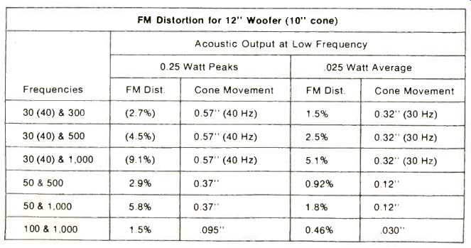
With these sobering facts in mind, let us use Greiner's tabular format for a 10" diaphragm and recast FM distortion for realizable cases. The formula used (4) is:
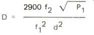
where f2 = modulated (high) frequency, in Hertz;
Pi = acoustical power output at ft , in watts;
f1 = modulation (low) frequency, in Hertz; and
d = cone diameter, in inches.
The advantage of this formula is that it avoids the need to calculate separately the amplitude of cone motion. For informational purposes. however, the peak-to-peak cone excursion for each case is included in the table.
It should be kept in mind that these FM distortion figures are those obtained under worst-case conditions--when the speaker system is pushed to its maximum low-frequency capability. This would rarely (if ever) be experienced in home use. But even if the numbers are not as high as those published by Klipsch and Greiner for absurd theoretical conditions, they are still rather large as conventional distortion figures.
Most impartial observers have expressed an inability to reconcile these large numbers with listening experience. It has been pointed out, correctly, is that there must be a major difference in annoyance value between FM distortion and some other kinds; otherwise, how would it be possible with such speaker systems to stage completely successful live-vs-recorded demonstrations, involving audibly perfect reproduction of complex live sounds such as that of a string quartet?
This proposition is supported by close examination of a process that everyone has experienced: listening to recorded music. Both tape machines and record players have mechanical imperfections that result in speed irregularities. Tape does not move by the heads at a perfectly uniform speed. A record does not revolve around the spindle at a perfectly constant speed. These deviations in speed are measured as percentages of the mean speed, and the word used to describe them is flutter. Flutter produces FM distortion just as the Doppler effect does.
As applied to loudspeakers, flutter would be the ratio of cone velocity at the modulating frequency to the velocity of sound in air, expressed as a percentage. On these terms, the maximum flutter would occur for two conditions described in the preceding table. Flutter under these conditions would be 0.52% peak. 0.33% average, for 0.25 acoustic watt output at 40 Hz: and 0.22% peak, 0.14% average, for .025 watt output at 30 Hz.
The NAB standard limit for reproducing turntable flutter is 0.1% average. If it is assumed that the flutter is sinusoidal this is equivalent to 0.16% peak. That assumption is not warranted for most turntables--even very high-quality units generate flutter peaks exceeding 0.16%. Moreover, the audio signal on the record has had already superimposed on it the flutter from two or more generations of tape recording and playback, as well as that of the recording turntable. The situation is likely to be worse for playback of recorded tapes. For either medium it is simply not realistic to expect occasional flutter peaks of less that 0.5%. This total amount of flutter produces FM modulation that is operative on all frequencies, even the very highest, and it is present in the same degree regardless of signal level. Yet it is considered to be marginally objectionable if at all.
Thus it is fair to say that under worst case conditions, the FM modulation distortion of high-quality direct-radiator speaker systems is comparable in magnitude to, or less than, the FM modulation distortion that is always present in the recorded signal anyway. If one is not audibly important, neither is the other. My guess is that people who claim to have heard loudspeaker Doppler distortion were really hearing nonlinear distortion in the speaker system, or amplifier overload.
Of course if all other things were equal it would be better to have no FM modulation distortion rather than even a small amount. It would be better to have no nonlinear distortion generated by the very high pressures in horn throats, rather than even a small amount. It does seem inefficient, however, to waste so much time and attention on trivial imperfections when there are important problems to be solved.
(1) Jordan, E. J., "The Design and Use of Moving Coil Loudspeaker Units," Wireless World, November 1970.
(2) Acoustical Engineering, Harry F. Olson, p. 524. Van Nostrand, 1957.
(3) Greiner, R.A., Letter to the Editor, Audio, December 1970, p. 14.
(4) Acoustical Engineering, Harry F. Olson, p. 190; Van Nostrand, 1957.
(5) See Audio, October 1971, p. 44.
Erratum
Sound Level Meter, December 1970 The resistor R6 should be 100 K as in the parts list, not 10 K as shown in the schematic. C11 should connect to the "flat" terminal of the switch, but not to C9 and C7. The output of the "A" filter should be taken from the junction of R14 and C5, not from C4 as shown.
(Audio magazine, Mar. 1971)
Also see:
Doppler Distortion in Loudspeakers (Aug. 1970)
Link | --Speaker Tests--Phase Response (by Richard C. Heyser) (Dec. 1974)
Speaker Tests: Room Test by Richard C. Heyser (Jan. 1975)
= = = =