by KEVIN BYRNE; Kevin Byrne is Product Manager for Ortofon, Plainview, N.Y. 11803.
The question of a component with impressive specifications and less impressive performance remains, despite the increasing sophistication of laboratory measuring instrumentation, a puzzle. The belief that such a blind spot exists in phono cartridge measurements led the technical staff at Ortofon of Denmark to construct a test procedure to measure the phase response of phono cartridges and correlate these findings with the other parameters that are normally measured.
The impetus for this work stemmed from earlier listening evaluations of phono cartridges that had resulted in a clear preference for moving-coil de signs over moving-magnet or moving-iron types. This was true despite the fact that test data, including amplitude response, trackability, separation, and harmonic distortion, did not point out any reason for the listeners' preference of the moving-coil design. The conclusion was that, while the conventional parameters were clearly important tools in predicting audible performance, they did not fully quantify all of the sonic differences among phono cartridge designs.
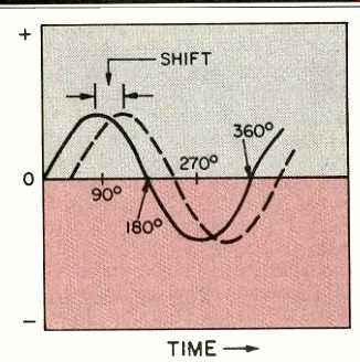
Fig. 1--Phase shift.
It is not generally realized by the audiophile that what he calls frequency response really has two parts: Amplitude versus frequency response and phase versus frequency response.
With electronics it is convenient to for get the phase response because it is generally linear, and therefore of no consequence, at the frequencies of interest. (We'll leave aside filters for the purposes of this article.) When we consider transducers such as phono cartridges, however, phase does play a part, because it is not linear in such devices. We therefore made a mathematical model, which we calibrated by measuring a cartridge that was the basis for the model. While the model is too lengthy to describe here, it was covered in a paper presented at the 71st Audio Engineering Society Convention in Montreux (Preprint No. 1866). Using measurements made with a B & K accelerometer for the 'phase response and with a conventional test record for the amplitude response, we were able to compare our model with actual test data and thus validate it.
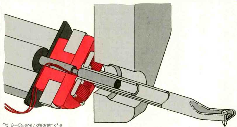
Fig. 2--Cutaway diagram of a moving-coil cartridge.
It is probably valuable at this point to go through some definitions and explanations. The phono cartridge's moving system is defined as the parts which vibrate in accordance with the modulations of a record groove. These parts include the stylus, cantilever, and the moving parts of the voltage-generating system. All of these, taken together, have a resonant frequency, which (in simple terms) is the frequency at which the moving system likes to vibrate. The natural resonance is the frequency at which such a moving system is operating at its highest efficiency. In phono cartridge terms, that means the frequency at which the cartridge delivers the most output signal voltage at constant input from the record groove.
The voltage-generating system is made up of all parts of the cartridge which are designed to convert the mechanical energy produced by groove modulations into the electrical energy which is the output of the cartridge.
These parts may include the coils, the magnet assembly or a magnetic shunt, and the pole pieces.
In a moving-coil design, the coil is part of the moving system, vibrating in a fixed magnetic field to produce the electrical signal. In a moving-magnet design, the magnet structure or magnetic shunt material vibrates such that its magnetic field passes through a fixed set of coils.
Phase in Moving-Coil Cartridges
Typically, the undamped moving-coil cartridge has an amplitude response which begins to rise in the 5 to 6 kHz region, climbs to about +8 dB at 20 kHz, and peaks at about 15 to 18 dB at 25 to 28 kHz. This undamped cartridge also has a large amount of phase shift, up to +180°, centered around the resonant frequency. This can be thought of as time distortion with respect to frequency or as a difference in the rate of rise or fall from what is expected from the calibrated model.
While the undamped moving-coil cartridge has only about 10° to 15° of phase shift at 20 kHz, with negligible amounts below 15 kHz, the amplitude response has a substantial error, which results in a very bright, subjective sound. The most usual method of reducing this rising high-end amplitude is to damp it with a suspension or rubber suspension donut.
Phase in Fixed-Coil Cartridges
Both the moving-magnet and the moving-iron types have moving systems with somewhat larger effective mass than moving-coil designs, and therefore their mechanical resonance points are at lower frequencies, ordinarily within the audible band. To obtain acceptable amplitude response, designers of fixed-coil cartridges have primarily used severe damping, a technique that increases the phase shift. As a result, these designs exhibit phase errors several times greater than those of a properly damped moving-coil design.
Fixed-coil cartridges also exhibit phase shift because of electrical resonance (at frequencies typically within the audible band) due to the self-inductance of the 2,000 to 3,500 turns of wire in these coils. The usual method used to damp this resonance is to load down the cartridge's output with a specific amount of capacitance in the cables between cartridge and preamp. Such capacitive loading also adds to the amount of phase shift, just as mechanical damping does.
Figure 3 shows the amplitude and phase response measurements for five different fixed-coil cartridges of different brands and types. Figure 4 shows the same two responses for four Ortofon MC200 moving-coil cartridges, each with a different amount of damping. In Fig. 3, there is little variation in amplitude response, only ±1.5 dB between 5 and 20 kHz, but phase responses vary from a shift of + 30° at 10 kHz to + 80° at 10 kHz. The worst-case example of the moving-coil types showed a shift of only + 20° at 10 kHz.
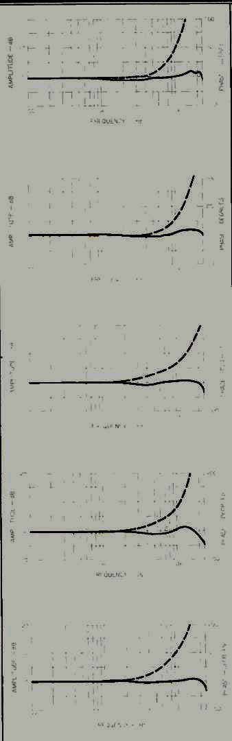
Fig. 3--Amplitude and phase response (dashed line) of five fixed-coil cartridges.
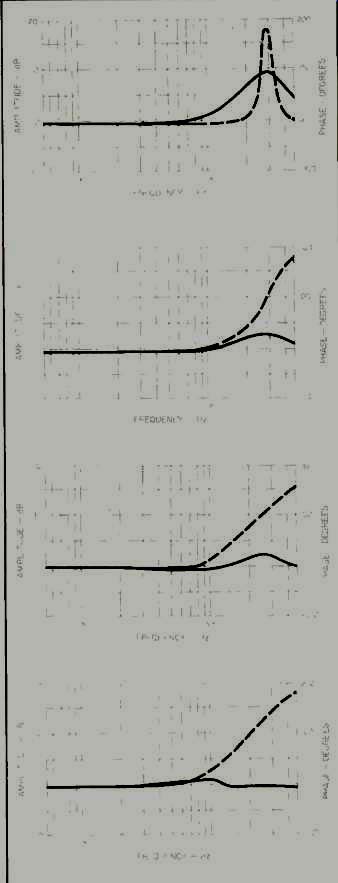
Fig. 4--Amplitude and phase response (dashed line) of four moving-coil
cartridges with various amounts of damping.
Listening Tests
In order to verify our theory about the audible effects of phase shift, we con ducted extensive listening tests with the four MC200 cartridges measured for Fig. 4. These cartridges ran the gamut, from one which was totally undamped, with a rapidly rising frequency response characteristic, reaching +7 dB at 20 kHz, to a heavily damped version which was ruler-flat in response, -0.3 dB at 20 kHz. The other two cartridges were moderately damped, with response peaks of +3.8 dB at 20 kHz and + 1.9 dB at 20 kHz respectively. The sonic differences among the sample cartridges were easily apparent. The locations of instruments, the overall sensation of depth and height, and the total width of the image all varied from sample to sample.
The totally undamped cartridge, which had the least amount of phase shift, produced the widest, deepest, and most stable image. The feeling of realism with this cartridge was unsurpassed. Unfortunately, its "bright" character could not be overlooked.
Overall balance was not correct, particularly with respect to female vocals, stringed instruments, and some of the percussion.
The second cartridge, which had the least amount of added damping, presented a sound stage which was slightly narrower and slightly taller, and which had a bit less depth. Localization and placement of instruments, however, remained very close to the undamped version's. Most importantly, the audible effect of any variation from absolute flat frequency response was minimal, and the feeling that the cartridge was too bright disappeared.
The third cartridge, with slightly more damping, sounded extremely similar to the second. Some shrinking of depth was detected on the vocal material, and very complex string pas sages exhibited slightly less definition of the instruments.
The fourth cartridge, which had the flattest amplitude response, was the least satisfying. The overall sound field had little depth; what depth existed was confined to center-stage information. Any difference in the locations of instruments placed in the same side of the stage was gone. Whereas the undamped cartridge presented a sound field which seemed made up Of numerous instruments placed in front of the listener, the sound field of the most damped cartridge seemed to have only three sound sources--left channel, right channel, and center channel.
It is important to note that all four cartridges exhibit amplitude responses which are essentially flat throughout all but a very small portion of the audible range. With the exception of the totally undamped version, which begins to show amplitude variations of +2 dB at 10 kHz and +5 dB at 15 kHz, the audible differences due to amplitude-response variations were negligible.
The audible effects of these phase variations appeared to be a reduction of depth of the sound stage, a lack of image stability, poor localization of sounds, and, in some instances, an image originating from above the loud speakers and remaining limited in width to the outside perimeter of the speaker setup.
Our conclusions from these measurement studies and listening tests are that it is indeed possible to measure phase shift in phono cartridges, and that this parameter directly relates to the sound produced by the cartridge. We are therefore trying to de sign cartridges which have both a flat amplitude response and relatively little phase shift. Our investigations at this time show that the moving-coil cartridge will typically exhibit less phase shift than a fixed-coil type, while its amplitude response is fairly easy to keep reasonably flat or balanced.
(Adapted from Audio magazine, Mar. 1983)
Also see:
How Phono Cartridges Work (Mar. 1982)
Birth of a Spec? PHONO CARTRIDGE NOISE (March 1977)
Understanding Phono Cartridges (Mar. 1979)
The Phono Cartridge Electrical Output Network (March 1981)