by Leonard Feldman

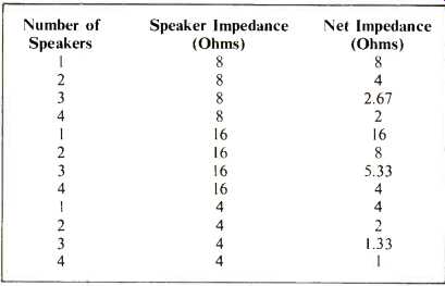
Countless articles have been written over the years concerning the problems and techniques employed in multiple speaker installations. Complex switching setups have been designed to maintain proper impedance match to each remote speaker system when all operate from a single channel of audio amplification. One of the virtues of a high fidelity component system is the fact that multiple speaker systems in more than one room can be tied to a single stereo amplifier or receiver. Normally, this "flexibility" is limited to two (or sometimes three) sets of speaker systems. Any attempt to increase the number of systems tied to a single stereo amplifier usually results in a net load impedance which is far too low for the typical solid-state output circuits used in today's component systems. Furthermore, with power subdivided amongst all the speaker systems, the audio power available to any single system (with all other systems active) is usually insufficient to produce sound pressure levels from the typical low-efficiency speaker systems which continue to dominate the high fidelity component scene. Table 1 shows what happens to the net impedance seen at the output terminals of an amplifier as more and more speaker systems are paralleled for simultaneous use, and it should be recalled that even so-called "8-ohm" speakers or 16-ohm speakers often exhibit impedances which are far lower than their nominal value at some specific frequencies.
Often, the audio enthusiast intent on having an elaborate multi-room, multi-speaker listening set-up will resort to the use of a 70-volt line system, such as that used in sound reinforcement (public address) systems, where distribution lines of hundreds of feet or more are required. For those not familiar with this system, let's review it briefly. A modern audio amplifier with a high degree of negative feedback may be regarded as a constant voltage source as long as its maximum undistorted power output is not exceeded. For example, an amplifier that can deliver 50 watts into an 8-ohm load will produce 20 volts rms of signal voltage across its output terminals when driven to full output. If the "load" is removed (speaker disconnected), the voltage across the amplifier's speaker output terminals will remain very close to 20 volts rms, because of the large amount of negative feedback applied from output to power amplifier input. If an audio transformer is connected to the output terminals, such that the voltage step-up is 3.5:1, the voltage observed at the secondary will be 70 volts. This voltage can then be "distributed" to various locations in much the same manner that the 117 volt a.c. power lines are distributed around your home. At each terminating point, another transformer is used to "step-down" the voltage to a suitable value for application to each loudspeaker. For example, if a given speaker is to draw 5 watts from the system, the secondary tap used on the terminating transformer at the speaker end of the line would be in the ratio of 1:11, since approximately 6.32 volts of audio signal would be required across en 8-ohm speaker load to develop 5 watts of audio power (E^2/Z = 5 watts; E =√5 x 8 = √40 = 6.32). Such matching transformers have their taps labeled in watts, rather than in impedance or voltage ratio. A typical network of five remotely installed speaker systems is shown in Fig. 1, with each speaker connected so as to "draw" a different amount of power from the amplifier.
While this type of distribution system is perfectly suitable for public address or voice reinforcement systems, the interposing of audio transformers in the system is generally frowned upon by the knowing audiophile who is more often than not delighted with the fact that a modern amplifier no longer requires an output transformer of any kind between the output stages and the speaker system. The output transformer used in the days of vacuum tube amplifiers was long regarded as the most critical part in an amplifier-the one most likely to introduce distortion and non-linearities in the system.
Headphone Distribution System
With the growing popularity of headphones for stereo (and even quadraphonic) music listening, I have been asked on many occasions to describe what would be needed to wire up every room in a home for stereo (or four-channel) headphone listening. Fortunately, most stereo headphones require just a fraction of the power needed by loudspeaker systems to produce high sound pressure levels. So sensitive are the average pair of stereophones, that power requirements are usually stated in milliwatts rather than in watts. As a result, if you were to examine the output circuitry of almost any stereo or quadraphonic amplifier you would find that a series resistor is usually wired between the actual power output stage of the amplifier and the familiar headphone jack terminals.
Typical values for this resistor range from 56 ohms to 270 ohms and the purpose of the series dropping resistor is twofold. Suppose, again, that we have a 50-watt per channel amplifier. Still treating it as a "constant voltage" source, if we were to disconnect all speakers from the amplifier, the rms voltage available at the output terminals would be close to 20 volts. Figure 2 shows what happens if we connect a headphone via the 100-ohm dropping resistor. If the nominal headphone impedance is 8 ohms, and the amplifier is driven to its maximum voltage output (remember, we can't speak about power in this circuit, only voltage, which at full output will be 20 volts rms), 7 1/2% of the total available voltage will appear across the phones, while the remaining 92 1/2% of 20 volts will be dropped across the series 100-ohm resistor. Under these conditions, approximately 1.48 volts will appear across the phone "voice coil," which corresponds to about 275 milliwatts for an 8-ohm phone. This is a value of power input that most stereo phones can sustain safely.
There is another reason for the series-dropping resistor and it has to do with the conversion efficiency of headphones.
Intuitively, you know that with phones tightly secured to the side of your head, it takes far less power to produce high sound pressure levels than is the case with even the most efficient type of loudspeaker. With a loudspeaker positioned many feet away from your ears and depending upon room air coupling to bring sound to you, sound pressure level is highly non-linear. In a dead room, volume decreases as the square of the distance from the listener. Thus, if you stand 8 feet from the speaker, loudness level will be one-fourth as great as if you were only 4 feet from the speaker. In the case of a set of phones, this relationship no longer holds true. Coupling is "almost direct," with a minimum volume of "trapped" air between the diaphragm of the phone and your auditory system.
Today's amplifiers have residual hum levels which are truly low-on the order of -90 dB or more with respect to full power output. If you were to connect a pair of phones directly to the speaker output terminals of an amplifier and, assuming you could reduce the master volume control until it is low enough so as not to "blow up" the phones, you would be faced with another problem-hum. As we have seen, if 275 milliwatts produces the same sound pressure level from the phones as we would have heard from a typical speaker with 50 watts applied, then the relative efficiency of the phones is nearly 23 dB higher than that of the speaker. Considered another way, the residual hum level heard over the phones when directly connected to the speaker terminals would be-67 dB, even with the volume control turned all the way counter-clockwise. At actual listening settings, hum level would be worse than that and clearly audible. By inserting the series resistor, maximum signal-to-hum capability is maintained and audible hum during phone listening is no more audible than when listening through loudspeaker systems.
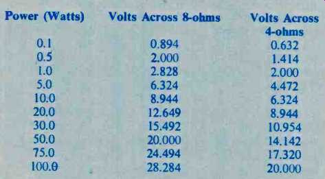
Fig. 1--"70 volt" sound distribution system using appropriate
taps on 70-volt matching transformers to determine maximum power delivered
to each of five remote speaker systems.
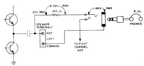
Fig. 2--Series resistor (100 ohms) drops most of output voltage permitting
maximum of 275 mW to reach headphones.
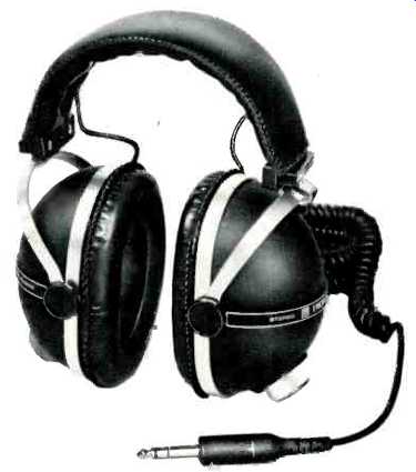
Fig. 3--These 8-ohm phones, Pioneer SE-405s, can handle 500 mW; require
only 11.25 mW to produce 113db.

Table II--Voltage required across 4-ohm and 8-ohm loads for various powers.
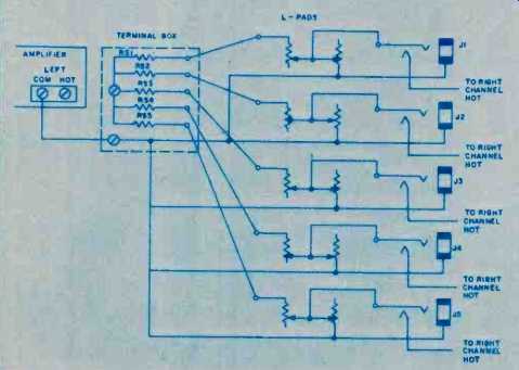
Fig. 4--One half (one channel shown) of five-location headphone distribution
system. Dual L-pads can be used for single-knob control of volume at each
location.
A Stereophone Network
Wiring up your house for headphone listening in each room is a good deal simpler than the same project applied to speakers. If you are going to use more than one type of stereophone, determine which is the least sensitive model you plan to use and how much audio input it requires for the sound levels you plan to use. Sometimes the input for phones is stated in millivolts for a given sound pressure level while in some instances a figure of milliwatts is given.
Consider, as a fairly typical example, the Pioneer SE-405 phones shown in Fig. 3. The specifications for this model tell us that maximum power input should be limited to 500 mW. Since they are 8-ohm phones, that means a maximum voltage input of 2 volts. However, the specs also spell out sensitivity as 113 dB with an input of only 0.3 volts. Suppose you want a sound pressure level capability of 119 dB (anything greater is likely to be painful, even if the phones can take it). To achieve the extra 6 dB you will have to double the voltage applied to the phones. Assuming a constant voltage amplifier you can easily translate the maximum continuous power output capability of your amplifier to a voltage value. A few typical values are given in Table II, but if you own an amplifier with some other power output capability, the formula for figuring the maximum available undistorted voltage is:
V= √(P_max x Z)
in which Pm is the maximum continuous power output (rated power) of the amplifier, per channel, and Z is the impedance for which that maximum power output has been stated.
Calculating the Series Resistance
Again, using a 50-watt amplifier as an example of the power amplifier to be used in driving the SE-405 phones, the value of series resistor needed is now calculated so as to obtain a maximum voltage across the phone jack (for each ear-phone) of 0.6 volts (double the 0.3 volts listed in the spec sheet for a 113 dB SPL).
Rs= Zp (V1-Vp)/Vp
R, is the required series resistor, Z, is the impedance of the phones to be used, V, is the total voltage available at the output of the amplifier at full power rating, andV0isthe desired voltage to be applied across the phones. In the case of our example,
= 8(20 - 0.6)/0.6 = 155.2/0.6 = 258.67 ohms
A 270-ohm resistor will be suitable, since it is the closest value available in 10% tolerance. In order to make sure that the resistor chosen can dissipate the power that will be developed through it, calculate the power from the voltage which is to be dropped across this series resistor. In the case of our example 19.4 volts will be the maximum that will ever be dropped across the 270-ohm resistor, so power will be a maximum of 19.42/ 270 = 376.36/270 = 1.39 watts. A two-watt resistor would be used to provide more than adequate safety, since under musical listening conditions, average power is likely to be much less than the maximum calculated.
Total wattage dissipated in each series resistor plus headphone of such a system would be 202/278 or 1.44 watts maximum. That means that using our 50-watt amplifier (with no loudspeakers operating simultaneously) we could wire up as many as 34 headphone outlets. While no home we know of has that many rooms, there is nothing to prevent you from wiring two or more outlets in a single room so that more than one person can enjoy headphone listening in the same room.
From the point of view of the amplifier, even if you had 34 such systems going at once, the net load impedance would be safe, at 278/34, or 8.18 ohms! Since there is a substantial amount of resistance in series with each phone outlet, it is perfectly all right to use thin wire (22 gauge or even 24 gauge) since even several hundred feet of this kind of wire will not contribute a significant percentage to the overall dropping resistance in each line. Using thinner gauge wire makes it easier to wire the system around the house, since such wire (often erroneously sold as "speaker wire") can be purchased in flat, almost invisible form and can be tucked under carpets, tacked along baseboards and the like, if you're not ambitious enough to run it through walls, under flooring or above ceilings.
Since the system was based upon the least sensitive phones to be used, if you plan to purchase more sensitive phones for additional locations, it would be a good idea to equip each phone outlet with a dual L-pad, gauged for stereo use. These are available in either 8-ohm or 16-ohm impedances. They serve not only as attenuators for the more sensitive phones in your system but can be used to turn off the phones entirely, at which time the line is loaded with a constant 8 ohms of impedance, maintaining the overall net impedance of the system regardless of how many phones are actually in use.
Naturally, if you plan to use 4-channel headphones now or in the future, you will want to run pairs of stereo lines to each location, with appropriately marked "front" and "rear" jacks at each outlet. It is not too important where you position the series-dropping resistor, although in very high powered amplifiers you may want to wire the series resistors near the amplifier end of each run, so that the actual voltage along the long length of wire is very low. Any convenient small chassis can be used as a terminal-box, with each resistor wired from the amplifier terminals to the terminals to which the long run of wire is connected. Of course, in the arrangement shown in Fig. 4, connection to the amplifier is made at the speaker terminals and not at the built-in headphone jack, since that self-contained jack already has a series resistor built into it which would upset all the calculations shown above.
Precautions for Quadraphonics
Many of the new four-channel receivers available today feature "stereo strapping" circuitry, in which a four-channel receiver can be used as a stereo receiver for higher power output by effectively paralleling pairs of amplifiers. When the receiver or amplifier is operated in this mode, most such components will not work properly if there is a common ground involved in the speaker (in this case, phone) hook-ups. Since standard stereo phone jacks do share a common ground for both stereo channels, the entire "terminal box" should be disconnected from your amplifier if it is to be used with stereo speakers in the "strapped" mode. Alternatively, you may want to include a toggle switch right on the terminal box so that the connections from amplifier outputs to distribution system can be broken when you want full power to be available for your speaker system listening or in cases where you are using a four channel amplifier or receiver in the "strapped" stereo higher power mode.
(adapted from Audio magazine, May 1974)
Also see:
Quadraphonic Headphones (Jun. 1973)
Dual Impedance Headphone Circuit (May 1975)
Piezoelectric Headphones (May 1975)
Why Electrostatics (May 1974)--Link |
= = = =