MANUFACTURER'S SPECIFICATIONS:
System Type: Three-way air suspension.
Frequency Response: 25 Hz to 20 kHz.
Impedance: 8 ohms.
Drivers: 12 in. high compliance woofer, 2-in. hemispherical dome midrange, 2-in. phenolic ring tweeter.
Crossover Frequencies: 1 500 Hz, 4500 Hz.
Controls: Three-position midrange, three position tweeter.
Cabinet Finish: Oiled walnut veneer.
Dimensions: 15 1/4 in. W x 13 1/4 D x 25 1/4 H.
Weight: Approx. 40 lbs.
Input Power: 10 watts minimum, 75 watts maximum.
Price: $174.95 each.
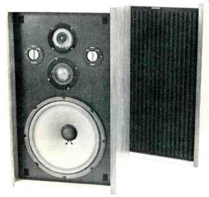
The Magnavox MAX 12 is a three-way loudspeaker system utilizing a 12-inch air suspension woofer, a 2-inch hemispherical dome midrange, and a 2-inch phenolic ring cone tweeter. While large enough to be treated as a floor-standing speaker, the cabinet is finished on four sides with an oiled walnut veneer and there is no provision for floor glides. The front grill is acoustically-transparent sculptured foam and the rear side of the cabinet, while not veneered, is stained to closely match the finished sides. Aluminum accent strips are attached to the front of the cabinet in such a way as to present a cosmetically attractive contrast to the walnut and black grill front. This reviewer recommends that this speaker be positioned in a living room in such a manner that there will be little temptation to place drinking glasses, ashtrays, or lamps on it, which could mar the finish.
The speaker grille is pressed onto Velcro fasteners and removed by pulling outwards on the handle formed by the black metal MAGNAVOX name tag. This name tag can be relocated to the long side of the grille for horizontal speaker box shelf placement, but this requires a Phillips screwdriver and locating a new hole on the backside of the grille frame.
One should also consider that with a weight of 40 pounds, only a very sturdy shelf should be used for the MAX 12.
The midrange and tweeter level controls are located on the front panel behind the grille. They can readily be adjusted without requiring access to the rear of the cabinet.
Each control is a three-position rotary switch and is marked: +3 dB, NOMINAL, and -3 dB. Speaker connection is made to knurled twist-knobs located in a recessed cavity on the rear. This allows the speaker to be positioned flat against a wall. The terminals are well marked and widely spaced for safe, easy connection.
A complete set of specifications, hookup recommendations, and user-oriented suggestions on amplifier power restriction is firmly cemented on the back of the cabinet. This is exactly where it belongs and Magnavox is to be congratulated on this.
Technical Measurements
The MAX 12 is rated as an 8-ohm system. The measured impedance is well above this value throughout the useful frequency range as shown in Fig. 1. With three-position midrange and tweeter controls, nine measurements would be required for complete characterization. Five of the combinations are shown in Fig. 1 and these were taken to show not only the maximum and minimum impedances, but the slight interdependence of control settings. System resonance occurs at 45 Hz. This speaker could be safely paralleled for drive by any amplifier capable of driving 4 ohms.
The magnitude of the on-axis, one-meter, anechoic frequency response for one-watt drive is shown in Fig. 2. It is not possible to present a simple representative plot, not only because of the nine possible control settings, but also because severe acoustic interaction occurs between the midrange and tweeter. Figure 2 therefore shows two basic measurements which are separated by 10 dB for clarity of presentation on one graph. The lowest curve, with SPL coordinates on the right of the graph, is for the Magnavox recommended positions of nominal for both midrange and tweeter. Bass response extends down to about 50 Hz then rolls off at the 12 dB per octave expected for a well-designed air-suspension system with the measured resonance shown in Fig. 1. The hemispherical-dome midrange is simply too good a high frequency reproducer to allow only the tweeter to handle frequencies above 4.5 kHz. The result is a response dip at about 6.5 kHz where their contributions become out of phase. This may be seen from the phase plot of Fig. 3, which is made for the same nominal midrange and tweeter level control settings. What is happening is that the woofer and midrange are in phase, producing a sound pressure increase for a positive voltage applied to the plus speaker terminal, while the tweeter is phased so as to produce the reverse polarity of sound pressure. Because of the difference in acoustic position of midrange and tweeter, Fig. 3 shows two plots. The upper phase plot, near zero degrees from 1 kHz to 3 kHz, is made by correcting the air path delay to the midrange and shows it to be in phase. The rapid phase transition at 3.5 kHz is due to crossover between midrange and tweeter. The lower phase plot is corrected for nominal tweeter air path delay and shows a phase of nearly 180 degrees above 7 kHz. (The break in the lower phase curve at 6.5 kHz is due to a 360-degree phase lag transition at this frequency where the midrange is still exerting some control. The data is plotted as a break rather than a precipitous step in phase for ease of presentation.) Referring back to Fig. 2, the dip due to nominal control positions can fortunately be overcome by readjusting the midrange control. The upper three amplitude response curves, with the left side SPL calibration, were measured for the midrange in the -3 dB position and all three tweeter control positions. The listening test, conducted prior to measurement, had indicated a more accurate sound for the -3 dB midrange position, hence this measurement. No phase data is included for this midrange position but suffice it to say the 360-degree transition at 6.5 kHz did not occur for the nominal and +3 dB tweeter positions.
The three-meter room response for the first 10 milliseconds of sound is shown in Fig. 4. The speaker was mounted against a wall, as recommended by Magnavox. The system was raised so that the center of the front face was at ear level, or one meter, in this test. The midrange and tweeter were set to NOMINAL and the measurement was made directly on axis and 30 degrees off axis in a stereo left channel position. The measurements are displaced 10 dB for clarity of presentation. The substantial dispersion of both midrange and tweeter allowed for a "filling up" of the dips of the anechoic response for Fig. 2 because of early sound scatter from ceiling and floor.
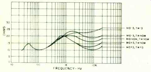
Fig. 1--Impedance plot for several combinations of midrange and tweeter
control.
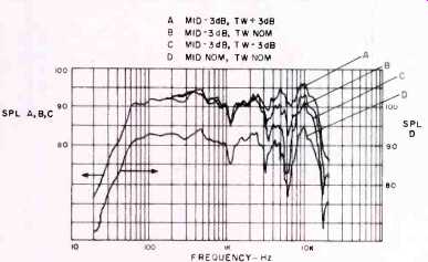
Fig. 2--One meter anechoic amplitude response for several midrange and tweeter
positions.
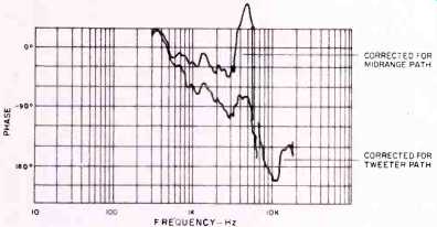
Fig. 3--One meter anechoic phase response for nominal midrange and tweeter
control.
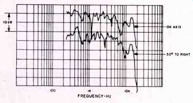
Fig. 4--Frequency response due to first ten milliseconds of sound in a preferred
room position measured at three meters. Curves displaced 10 dB for clarity.
Fig. 5--Harmonic distortion for the musical tone and E1, A2, and A4.
Harmonic distortion for the musical tones E1, A2, and A4 s shown in Fig. 5. The intermodulation distortion of A4 by E1 when mixed in equal power is shown in Fig. 6. The harmonic distortion is primarily second harmonic for the lower pitched tones. The intermodulation of A4 is mostly due to amplitude modulation with only a small phase modulation contribution at the maximum power levels tested. Crescendo handling measurements, as well as these more conventional measurements, suggest that the Magnavox-recommended power limitation of 75 watts is a realistic upper limit for quality reproduction.
The polar response for three combinations of midrange and tweeter control is shown in Fig. 7. The fact that both the midrange and tweeter have wide angular dispersion is quite evident. The partial cancellation of midrange and tweeter is indicated by the same frontal axis energy for two positions of midrange control. However, on an energy basis, the polar response indicates that relatively uniform sound should be obtained within 45 degrees to either side of the frontal axis.
Strong room reflection may be expected due to this property and the speaker may tend to sound bright in a sparsely furnished room.
Figure 8 is the transient energy response measured one meter on axis. The position of some major physical elements in the MAX 12 is shown for comparison. The separate contributions of the tweeter, midrange, and woofer high frequency components are quite evident. As a basis for comparison, if this loudspeaker were perfect, the plot would yield a single energy hump around 2.9 milliseconds with most of its energy concentrated within a period of one tenth millisecond. No speaker is perfect, however, and Fig. 8 is the amount by which the MAX 12 disperses an impulse.
Fig. 6--IM of A, by E, mixed
Fig. 7--Polar energy.
Fig. 8--Energy-time response to a perfect pulse band limited d.c. to 20 kHz.
Listening Test
Magnavox provides the purchaser of the MAX 12 a detailed set of recommendations for proper operation. These were followed as closely as possible for the listening test so as to best represent the conditions a purchaser might encounter. The speakers were placed along one wall and raised so that the center of the front face was approximately at ear level when sitting in a chair.
Vertical mounting, with the MAGNAVOX name tag erect, produces better stereo imagery than a horizontal mounting such as might be considered for shelf placement.
This is probably because of the vertical "totem pole" alignment of woofer, midrange, and tweeter. A horizontal mounting produces audible stereo image wander as one changes his listening position. Good lateral stereo imagery, however, is available from a vertical mounting configuration.
Good high frequency balance may be, obtained with the speakers flat against the wall. The general impression with both controls at NOMINAL is that of a "hot" midrange. While this provides a good sense of presence for vocals, particularly those with a center-stage position, a more realistic, overall balance was obtained with the midrange in the-3 dB position and the tweeter left at NOMINAL. Though bass response measured down to 50 Hz, it appeared to this reviewer to be just a shade "thin" when compared to other acoustic suspension systems of the same physical size.
Some bass equalization was thus felt necessary for a better sense of realism. Corner placement of the speakers may prove desirable in some listening situations in order to provide a firmer bass.
Close miced vocals and electronically reproduced instruments are quite adequately reproduced. Lateral stereo imagery was quite acceptable with no hole in the middle or jumping about of a center image with change of listening position.
Radial stereo imagery, however, which gives the sense of depth, was not entirely to this reviewer's satisfaction. Most of the sound image appeared compressed in range so as to give a more nearly two-dimensional portrayal of some stereo material known to have good depth. Orchestral and choral presentations appeared to suffer from foreshortening.
The Magnavox MAX 12, in this reviewer's opinion, while doing a creditable job with wide-range material, appears best suited to the reproduction of contemporary music, which can place strong demands on the 1 kHz to 7 kHz range.
-Richard C. Heyser
( Audio magazine, May 1974)
Also see:
Magnavox 8898 Receiver (Mar. 1973)
Magnavox CD650 CD player (Mar. 1987)
Cambridge Physics Model 310 Loudspeaker (Nov. 1982) , and AKAI 4000DS Tape Deck (May 1974)
= = = =