Manufacturer's Specifications:
FM Tuner Section:
Usable Sensitivity: Mono, 9.8 dBf (1.7 µV).
Fifty-dB Quieting Sensitivity: Mono, 14.8 dBf (3.0 uV); stereo, 35 dBf (31 µV).
S/N: Mono, 88 dB; stereo, 76 dB.
Stereo Separation: 58 dB at 1 kHz; with high-blend filter, 20 dB at 1 kHz.
Alternate Channel Selectivity: 85 dB, narrow i.f. bandwidth.
Capture Ratio: 1.0 dB, normal i.f. bandwidth.
Image Rejection: 85 dB.
I.f. Rejection: 120 dB.
Spurious Rejection: 95 dB.
THD: Mono, 0.06% at 1 kHz; stereo, 0.07% at 1 kHz; both normal i.f. bandwidth.
Frequency Response: 30 Hz to 15 kHz, +0,-0.5 dB.
Muting Threshold: High, 40 dBf (55 µV); low, 20 dBf (5.0 uV).
Stereo Threshold: 20 or 40 dBf.
Subcarrier Product Rejection: 65 dB.
AM Tuner Section:
Sensitivity: 300 uV/meter, loopstick antenna.
Image Rejection: 50 dB.
I.f. Rejection: 85 dB.
Selectivity: 45 dB, ±20 kHz.
Distortion: 0.3%.
Amplifier Section:
Power Output: 85 watts per channel, 8-ohm loads, both channels driven, 20 Hz to 20 kHz.
Rated THD: 0.015%.
SMPTE IM: 0.015%.
Damping Factor: 50 at 8 ohms, 1 kHz.
Slew Rate: 60 V/µS.
Rise-Time: 1.0 µS.
Sensitivity for Rated Output: High level, 150 mV; moving magnet, 2.5 mV; moving coil, 125 µV.
Frequency Response: 20 Hz to 20 kHz, ±0.3 dB.
Phono Overload: Moving magnet, 200 mV; moving coil, 10 mV.
S/N: High level, 100 dB; moving mag net, 86 dB; moving coil, 68 dB.
Tone Control Range: Bass, at 500-Hz turnover, ± 10 dB at 100 Hz; treble, at 2-kHz turnover, ± 10 dB at 10 kHz; midrange, at 800-Hz turnover, ± 10 dB at 800 Hz.
Tone Control Turnover Range: Bass, 100 to 500 Hz; treble, 2 to 10 kHz; midrange, 500 Hz to 2 kHz.
High Filter: -6 dB at 10 kHz, 6 dB/ octave.
Subsonic Filter: -3 dB at 20 Hz, 12 dB/octave.
Loudness,-30 dB: +7 dB at 100 Hz, +3.5 dB at 10 kHz.
General Specifications:
Power Requirements: 120 V a.c., 60 Hz.
Dimensions: 18 1/8 in. (46 cm) W x 5 3/16 in. (13.2 cm) H x 14-9/16 in. (36.9 cm) D.
Weight: 27.1 lbs. (12.3 kg).
Price: $855.00.
Company Address: 7 Powder Horn Dr., Warren, N.J. 07060.
above: Neat and knobless main control section of the R-851 concentrates
tuning functions (including seven presets each for AM and FM) to the
left, general audio functions at the right. Hinged lower flap conceals
tone controls, speaker selector, MM/MC phono selector, and other miscellaneous
controls.
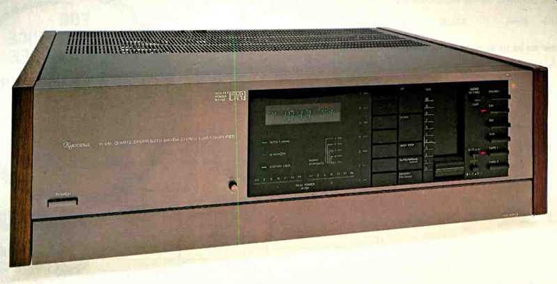
Kyocera and Cybernet are corporate relatives, and this time the corporate decision has been to bring out a line of receivers (or tuner-amplifiers, if you insist) under the Kyocera brand name. The top unit in that line is the Model R-851, a frequency-synthesized, full-featured AM-FM tuner combined with an equally full-featured preamplifier-power amplifier capable of delivering in excess of 85 watts per channel into 8-ohm loads.
I must warn you at the outset to ignore the major published specifications of this receiver. Too many of them are optimistic. Why it was necessary for Kyocera to engage in a game of "specsmanship" I don't know; the receiver is a good performer and has many excellent control features which work well. Couldn't they have been content with a 0.05% rated distortion spec (which the amplifier section easily meets) instead of claiming a 0.015% spec (which it fails to meet)? Signal-to-noise ratio of 70 dB in stereo FM is a perfectly respectable performance spec for a frequency-synthesized tuner. So why do you suppose Kyocera has to claim S/N of 76 dB (or 88 dB in mono) when it actually makes only 73 dB? Having gotten that off my chest, let's examine the nicely laid-out front panel of this receiver. Kyocera has wisely chosen to cover the less-often-used controls with a hinged, swing-down door along the lower edge of the dress panel.
With the door obscuring the secondary controls, the panel takes on an uncluttered look. At the extreme left is a power on/off switch. Near panel-center is a multi-function display consisting of a frequency readout (AM or FM), stereo indicator light, five-LED signal-strength display, and a power output per channel LED display. The latter can be switched between two ranges so that even at low listening levels, the display will be active. The display section also incorporates indicator lights to tell you which tuning mode you are in (auto or manual), which i.f. mode has been selected (narrow or normal) and when a station has been "locked in" by the quartz-synthesized tuning circuitry.
To the right of the display area is a vertical row of seven station-preset buttons, each of which can recall an AM and an FM station frequency previously committed to memory.
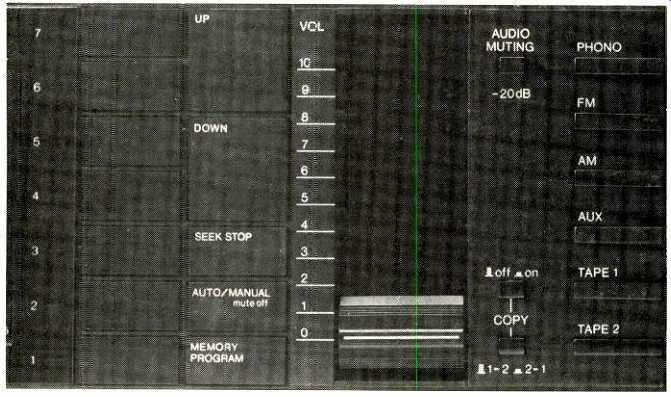
Additional touch buttons to the right of these are used for up and down tuning, selecting auto-seek tuning or incremental manual tuning, and memorizing desired station frequencies.
A calibrated, vertically oriented, master volume slider control is located to the right of these buttons, and to its right are an "Audio Muting" switch and a pair of switches related to the tape copying functions of the receiver. Six program-source pushbuttons ("Phono," "FM," 'AM," "AUX," "Tape 1" and "Tape 2") are located at the extreme right of the front panel.
When the hinged door is swung down, the additional controls that are revealed include two speaker selector switches; bass, midrange and treble controls. each equipped with continuously variable turnover controls; tone, subsonic and high-filter on/off buttons; switches for FM mute threshold, i.f. bandwidth, blend on/off and 25/75-µS de-emphasis; a channel balance control; loudness on/off, stereo/mono and MM/MC phono switches, and a stereo phone jack. As you can see, there isn't much by way of controls that Kyocera has chosen to omit from this, their top receiver.
The rear panel of the R-851 has only one connection terminal for an FM antenna transmission line, and it is of the coaxial, 75-ohm F-type. Kyocera supplies a 300/75-ohm transformer it its bag of accessories for those who want to connect 300-ohm, twin-lead transmission lines to the receiver. AM "hot" and "ground" antenna terminals are also found on the rear panel, as are the usual array of input and tape output jacks, a turntable ground terminal, polarized spring-loaded speaker terminals, a rotatable AM loopstick antenna, and three convenience a.c. outlets (one switched, two un switched).
FM Measurements
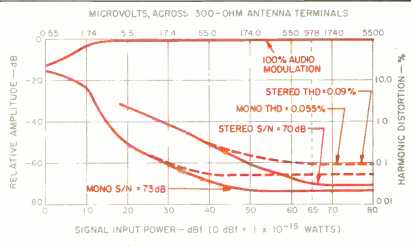
Fig. 1--Mono and stereo quieting and distortion characteristics, FM section.
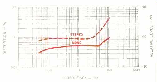
Fig. 2--THD vs. modulating frequency, FM tuner section.
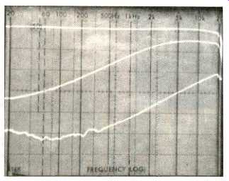
Fig. 3--FM frequency response and stereo separation. Middle trace is
separation with blend switch activated.
Usable FM sensitivity in mono measured 12.0 dBf (2.2 uV across 300 ohms). Stereo usable sensitivity measured 20 dBf (5.5 uV across 300 ohms). Fifty-dB quieting required a signal level of 20 dBf in mono; the figure of 39 dBf for stereo is not particularly outstanding but nevertheless acceptable.
With the standard "strong signal" level of 65 dBf applied to the antenna terminals, signal-to-noise ratio in mono leveled off at 73 dB, while in stereo, the best S/N obtainable was 70 dB for the same or greater signal strengths. Using a 1-kHz modulating signal, total harmonic distortion decreased to a low of 0.055% with strong signals in mono and 0.09% in stereo. These are both excellent figures, even though the stereo result falls short of Kyocera's claimed 0.07%. Quieting and mid-frequency distortion characteristics are plotted as functions of incoming signal strength in Fig. 1. Figure 2 is a graphic plot of THD versus modulating frequency for the FM tuner section of this receiver, operated in both the mono and stereo modes. In mono, THD measured 0.045% at 100 Hz and 0.07% at 6 kHz. In stereo, harmonic distortion was 0.09% at 100 Hz and 0.2% at 6 kHz.
Figure 3 is a 'scope photo of a spectrum analysis sweep from 20 Hz to 20 kHz, with the upper trace representing the frequency response at the output of the modulated left channel and the lower trace showing the crosstalk or separation as measured at the output of the unmodulated channel. The middle trace shows what happens to separation when the blend switch is activated, as it might be used to reduce background noise during reception of weak stereo signals. I measured a mid-frequency separation of between 45 and 47 dB (depending upon which channel was measured), far short of the 58 dB claimed by Kyocera, but certainly more than adequate for "real-world" stereo FM reception. For a modulating frequency of 100 Hz, the separation was 48 dB; it dropped to 27 dB at 10 kHz.
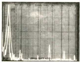
Fig. 4--FM stereo crosstalk components, 5-kHz modulating signal.
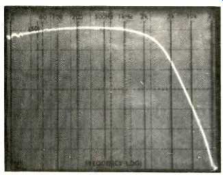
Fig. 5--AM frequency response.
Figure 4 shows what happened when I applied a 5-kHz signal to the left-channel input of the FM generator at 100% modulation level. The tall spike at the left denotes the desired output signal. A second linear sweep (from 0 Hz to 50 kHz) was then made with the analyzer input connected to the output of the unmodulated (opposite) channel. The short spike nestled inside the taller one shows the relative level of the 5-kHz crosstalk appearing in the unmodulated channel.
Other components at higher frequencies (to the right) represent levels of harmonic distortion, subcarrier and crosstalk products in the output of the unmodulated channel.
Capture ratio measured 1.5 dB. Alternate channel selectivity measured 85 dB in the narrow position, dropping to around 45 dB in the normal i.f. bandwidth setting, as might be expected. I.f., image and spurious rejection were all between 95 and 100 dB. Though not specified by Kyocera, AM suppression measured a satisfactory 55 dB. Figure 5 is a plot of frequency response for the AM tuner section.
Power Amplifier and Preamplifier Measurements
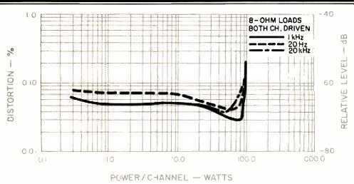
Fig. 6--Distortion vs. power output per channel, at three frequencies.
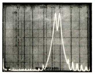
Fig. 7--Spectrum analysis of IHF-IM components, using 9- and 10-kHz twin-tone
test signal.
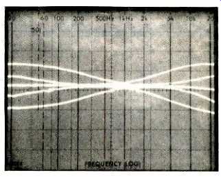
Fig. 8--Range of variable-turnover bass and treble tone controls.
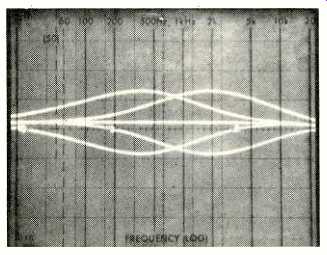
Fig. 9--Range of variable-turnover midrange tone control.
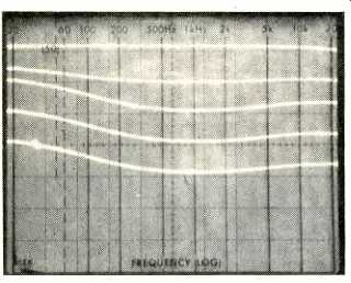
Fig. 10--Loudness compensation at various settings of master volume control.
The power amplifier section of the Kyocera R-851 was able to deliver nearly 100 watts per channel before there was any evidence of real clipping. However, at lower power levels (including its rated level of 85 watts per channel driving 8-ohm loads) the total harmonic distortion level never got down as far as the 0.015% specified (FTC take note!).
So, based on the FTC rule, I guess I'd have to say (facetiously, of course) that the amplifier is incapable of delivering any power at its rated distortion. But seriously, folks, at 85 watts output per channel, THD measured only 0.03% for a 1-kHz signal, 0.045% at 20 Hz, and 0.08% at 20 kHz. The SMPTE-IM distortion for that same output level was only 0.03% (but not 0.015% as claimed). These results are plot ted as continuous power output versus distortion levels in Fig. 6. The CCIF-IM distortion measured 0.03%, while IHF IM, calculated from the spectrum analysis sweep of a two tone input signal in Fig. 7, worked out to be 0.17%. All of these results are perfectly respectable and are not likely to introduce audible artifacts when listening to music.
Damping factor was approximately 50, as claimed, measured at 50 Hz and with 8-ohm loads. (Kyocera quotes damping factor for 1 kHz, 8 ohms.) Dynamic headroom was approximately 1.0 dB.
The combination of bass, treble, and midrange tone controls, all with variable turnover, makes for an extremely flexible tone control system. Kyocera refers to this control group as a parametric equalizer. I wouldn't go quite that far (parametric equalizers can usually vary the "Q" of their filter bands, as well as center frequencies and amplitude), but I will admit that it comes pretty close.
Figure 8 plots the maximum boost and cut characteristics of the bass and treble tone controls found on the R-851 One set of curves was taken with the variable turnover controls associated with each tone control turned fully clockwise, and the other set was taken with the variable turnover knobs rotated fully in the opposite direction. So as not to make the display too confusing, the action of the midrange control and its associated variable turnover control is plotted separately in Fig. 9. Figure 10 shows the action of the loudness compensation control as the volume control setting is lowered in steps of approximately 10 dB.
Input sensitivities and signal-to-noise ratios for the various high- and low-level inputs of this receiver were all measured relative to the new IHF reference levels and will therefore not agree with Kyocera's published figures. (I wonder when some of these manufacturers are going to start realizing that most of us don't listen to our systems at rated output, and that therefore signal-to-noise ratios referred to rated output are meaningless.) In any event, I measured input sensitivities (for 1-watt output) of 0.29 mV and 14.5 µV for the MM and MC phono inputs, respectively. High-level input sensitivity measured 17 mV for 1-watt output.
Signal-to-noise ratio for the MM phono input, referred to a 5-mV input and a 1-watt output, measured 79 dB. For the MC phono input, referred to 0.5-mV input, S/N was 77 dB; for the high-level inputs, referred to 0.5-V input, it was 81 dB. All S/N measurements are A-weighted.
Frequency response for the high-level inputs was flat within 1 dB from 9 Hz to 35 kHz and within 3 dB from 5 Hz to 65 kHz. RIAA equalization was accurate to within 0.2 dB from 30 Hz to 15 kHz. MM phono, overload measured 150 mV (as against 200 mV claimed), but, surprisingly, MC phono overload was 20 mV (as against only 10 mV claimed by Kyocera). The-3 dB cutoff points for the subsonic and high filters were at 20 Hz and 9 kHz respectively.
Use and Listening Tests
Once I got over my resentment of the inflated published specifications, I found the Kyocera R-851 to be a very well-designed receiver, both in terms of ergonomics and its actual audible performance. Tuning of both AM and FM stations was totally accurate and drift-free, as you would expect from a frequency-synthesized system. The indicator lights on the exposed part of the front panel serve as helpful reminders of the status of the most often used switches without looking like a neon storefront. With all rotary control knobs recessed and hidden behind the hinged door, the front panel of the R-851 is extremely elegant looking, with no protrusions whatsoever to break up its clean lines.
Using medium-efficiency KEF 105.2 reference speakers, the 85-plus watts per channel available from this receiver proved equal to the task of reproducing several compact digital discs at adequate loudness levels. Sound was very clean, and I am discovering that the use of digital software (either PCM tapes or CD discs) is a great way to zero in on whatever sonic deficiencies a given piece of electronic equipment may try to hide behind noisier, more-distorted analog-program sources.
The extra gain provided by the MC phono input was more than enough to work with several moving-coil cartridges in my pickup collection. Surprisingly, hum and noise using the MC pre-preamp facility were barely more than was heard in the MM phono mode.
The suggested retail price for this receiver does not seem out of line in terms of its power output capabilities, control features, and general performance level. If you like its lay out, ignore the spec sheet and enjoy!
-Leonard Feldman
(adapted from Audio magazine, May 1983)
Also see:
Link | --Kyocera DA-710CX CD player (Aug. 1987)
= = = =