Equivalent Mass
For static balance, the mass of the arm tube, the headshell and mounting accessories, and the cartridge itself, which lie on one side of the horizontal bearing, must be balanced by a counterweight on the opposite side. The counterweight can usually be moved to first achieve perfect balance and to another position to supply VTF. In some designs, additional weights or springs are used to provide vertical tracking force, but these are ignored for the sake of simplicity in the analysis below.
Consider the arm of Fig. 9, consisting of a weightless tube and a cartridge of mass M including the head shell, etc., counterbalanced by a counterweight 10 times the mass of the cartridge, or 10 M. Then, if the distance of the cartridge from the bearing is 10 x units, the distance of the counterweight for perfect balance is x, or one-tenth of the distance of the cartridge. This arm has an inertia given by the various masses times the square of their distances from the bearing. Thus, the respective contributions will be:
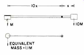
Fig. 9--Analysis of equivalent tonearm mass considers the length from stylus
to pivot point (10 x) and length from counterweight to pivot (x).
Cartridge inertia = M(10x)2 = 100Mx2; Counterweight inertia = 10 M (x)2 = 10 M x2.
Therefore, total arm inertia = 100Mx2+10Mx2=110Mx2.
It can be seen that the contribution of the cartridge, although only one tenth the weight, is much larger than that of the counterweight, because the cartridge is further from the bearing.
Also, if a longer arm tube is used, the inertia of the arm increases as the square of the tube length (x), given the same cartridge and counterweight.
Arm inertia can be lowered by reducing either mass or the length of the arm.
We can now introduce the concept of the equivalent mass of the tonearm.
By Newton's second law of motion, force equals mass multiplied by acceleration, or acceleration equals force divided by mass. If we can find a mass which, when substituted for all the arm masses and placed at the stylus, will accelerate at the same rate as our arm when subjected to the same force applied at the stylus, this will be its equivalent mass. The equivalent mass can be calculated by the reverse process used for calculating inertia, since the distance of the cartridge was 10 x and inertia was 110 M x2.
Equivalent mass =110Mx2/ (10x)2 = 1.1 M.
Note that the mass of the cartridge alone was M and that the calculated equivalent mass, 1.1 M, includes the contribution of the cartridge and the counterweight, but not of the rest of the arm. In a real case, similar contributions will be made by every component in the arm according to its mass and to its distance from the bearing.
While the calculation will be more complex, it is based on the same principle.
It can also be shown that if a lighter counterweight is used, the equivalent mass of the arm increases. If the counterweight is used, the equivalent mass of the arm increases. If the counterweight mass is halved to 5 M for static balance, it will have to be placed at twice the distance from the bearing, or at 2 x. Then,
Equivalent mass
=100Mx2+5M (2 x)2 / (10x)2
=1.2Mx2.
Thus, the equivalent mass increases to 1.2 M by halving the weight of the counterweight.
The equivalent mass plays its primary role as a part of the vibrating system (as explained under tonearm resonance), but it also has a secondary role. For slow movements of the record surface, such as with track warps, the force required to move the arm depends on its inertia or equivalent mass. The higher the equivalent mass of the arm, the larger the force required from the record to push the arm up. Conversely, the larger the inertia, the larger the VTF required to pull the arm down to maintain contact between the stylus and the record.
Resonance
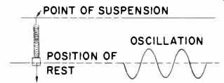
Fig.10-Basic analysis of oscillation.
If a mass is suspended at one end of a spring (Fig. 10), the other end of which is fixed, the spring will extend (depending on its stiffness and the size of the mass) to attain a fixed "mean" position of rest. If the mass is displaced from its position of rest and released, it will oscillate at a frequency called its natural, fundamental, or resonant frequency. The resonant frequency (f), a function of the stiffness of the spring (k) and the suspended mass (m), is given by the equation:
f = (1/ 2π) √(k/m)
The equation shows that resonant frequency rises for stiffer (or lower compliance) springs and for lower masses.
If the point of suspension vibrates, the mass will also move, but the movement will depend on the oscillating frequency. The mathematical analysis of the phenomenon is known as the theory of forced vibration.
Below the resonant frequency, the end being oscillated and the mass move virtually together as if they were rigidly connected, and relative movement between the mass and the point of suspension is virtually zero, as shown in Fig. 11A.
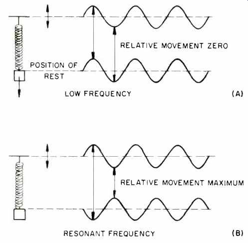
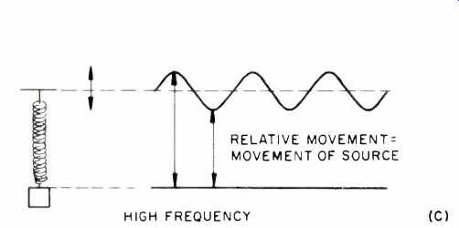
Fig. 11-Relative movement of the weight depends on the oscillation frequency.
With increasing frequency, amplitude of the mass increases but the movement of the mass follows a short time after the movement of the other end. The resonant condition occurs at the same frequency as for free oscillation, where the mass and the point of suspension move "out of phase." When the point of suspension moves down, the mass moves up, and vice versa. Relative movement between the mass and the point of suspension will be largest at this frequency and equal to the sum of the amplitudes of the forcing vibration and the resonance movement, as shown in Fig. 11B. As frequency increases again, this out-of-phase movement decreases, and the movement of the mass progressively decreases. Relative movement will also decrease. At a very high frequency, the mass remains completely still, even though the point of suspension moves as vigorously as ever, as shown in Fig. 11C. The relative amplitude of the mass is plotted in Fig. 12 against frequency, the amplitude of the point of suspension which forces vibrations being assumed to be constant. This is a very important phenomenon and can be used to explain many facets of performance in cartridges, tonearms, and turntables. Resonance phenomena occur wherever masses are connected by springs (all materials have some flexibility and mass); the only differences are the amplitudes and frequencies of the resonant modes.
Tonearm Resonance
All tonearms form a resonant system, with the equivalent mass of the tonearm acting together with cartridge compliance as the spring. This resonance may be called its primary resonance (also called bass, fundamental, or simply tonearm resonance), and in commercial systems available today, the resonant frequency generally lies between 5 and 25 Hz.
Applying forced-vibration theory to tonearms, it is seen that if the oscillating frequency is far below the resonant frequency, such as is caused by low-frequency warps and similar faults in the record, both the stylus of the perfect cartridge and its tonearm faithfully follow the record warps. There is no relative movement between the record and the tonearm so that the electrical output is zero. The cartridge suspension acts as if it were a rigid connecting member, and the only force exerted by the record is that required to move the equivalent mass of the arm. This is one of the advantages of a tonearm with a low equivalent mass.
At frequencies far above the resonant frequency, such as at the audio frequencies of the signal on the record, the tonearm does not move.
Stylus movement is transferred directly to the armature and converted to an electrical signal. The primary resonance of the tonearm has no influence on cartridge performance.
At the resonant frequency, and near it, the tonearm moves in a direction opposite to the direction of stylus movement. This is an out-of-phase condition, and tonearm movement can be many times larger than the stylus movement. The large relative movement between the tonearm and the stylus produces a peak in the frequency-response curve at the resonant frequency. Response on either side of this peak will fall at 12 dB/octave below the resonant frequency. A typical response curve is shown in Fig. 13.
The movement in a direction opposite to that of the record can be so large that the cantilever cannot move the required distance, and contact between the record and stylus is lost. In less violent cases, tonearm vibration results in changing VTF at a rate corresponding to the resonant frequency, with unpredictable effects on cartridge tracking.
Another undesirable effect is the accentuation of rumble. Signals generated in the cartridge at low frequencies are boosted by up to 20 dB in the phono preamplifier because of the replay equalization necessary to compensate for recording characteristics. Any rumble present in the turntable or on the record will first be amplified by the tonearm resonance and then boosted by the record equalization. Also, the presence of a large subsonic signal induced in the cartridge by the movement of the tonearm at its resonant frequency can modulate the audio signal and create intermodulation products. These distortion products cannot be removed by any later process once they are generated.
The effects of the primary tonearm resonance are minimized if its frequency is at a point where warp frequencies seldom occur and amplitudes are small. Studies made of the distribution of warps in phonograph records show that the majority of warps lie at frequencies below 10 Hz.
It is therefore logical to design the tonearm resonance to lie well above this frequency.
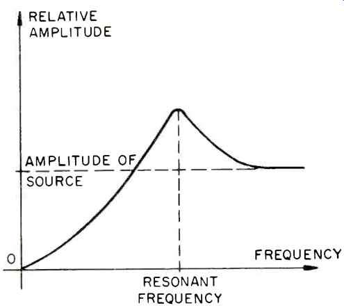
Fig. 12-Amplitude of the mass versus frequency, with the amplitude of the
source held constant.
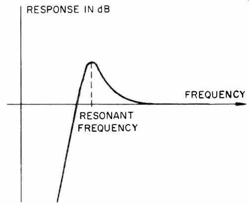
Fig. 13-Typical tonearm-cartridge resonance curve.
However, if the resonant frequency is too high, the electrical output of the cartridge will be influenced by audio frequencies, resulting in a boost at the lower end of the audio spectrum. A tonearm resonance well above 10 Hz, but below the recorded audio signal frequencies, demands not only a light tonearm and cartridge, but a cartridge compliance that is closely matched to the equivalent mass of the tonearm.
Two methods are commonly used to reduce the effects of tonearm resonance, especially when it lies in the danger region below 10 Hz: The use of a flexibly mounted counterweight and damping the tonearm.
Flexible Counterweight Mounting
In the majority of tonearms the counterweight is rigidly mounted, but in some, a flexible mounting is used.
Although a reduction in equivalent mass is often claimed when such a "decoupled" counterweight is used, the actual explanation is more complex. To understand what happens, the properties of a "dynamic absorber" must be examined, which is an extension to the forced vibration theory explained above.
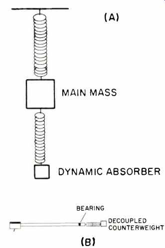
Fig. 14--Analysis of oscillation in a tonearm with a decoupled counterweight.
If the mass in Fig. 10 is divided into two parts that are rigidly connected, the resonance phenomenon will be unchanged from that explained in the theory of forced vibration. However, suspending one of the parts flexibly below the other results in the system shown in Fig. 14A. It can now be seen that there are two resonant systems, the first or main mass on the first spring, while the second mass, which is called the dynamic absorber, has its own natural resonance when the main mass acts as the forcing source. The equivalent tonearm with a decoupled counterweight is illustrated in Fig. 14B. At frequencies far below its own resonant frequency, the mass will act as if it were rigidly connected to the point of oscillation and will move together with it. If this frequency is also far below that of the absorber, it will also move together with the mass. By the same argument, at frequencies far above either resonant frequency, both the mass and the absorber will remain still. Thus, at frequencies not near either resonant frequency, the system acts as if both the mass and the absorber were a single mass and as if the second spring did not exist. Extending this result to a tonearm, it can be seen that a flexibly mounted counterweight has no effect on resonances at frequencies far below or above the natural resonant frequencies of both the tonearm and its counterweight.
If the individual resonant frequencies of the main mass and the absorber are identical and the forcing vibration operates at this frequency, the main mass will not move since all the energy supplied at the point of oscillation of the main mass is being used to move the damper. Relative movement between the point of oscillation and the mass is the same as the movement of the point of oscillation alone, and relative movement is zero. Extending this result, in the case where the resonant frequency of the counterweight is identical to the tonearm, there will be peaks in the response below and above the natural resonant frequency of the tonearm.
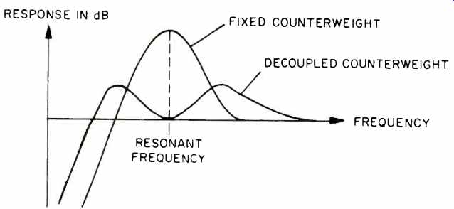
Fig. 15--Typical tonearm-cartridge resonance curve when the tonearm has
a decoupled counterweight.
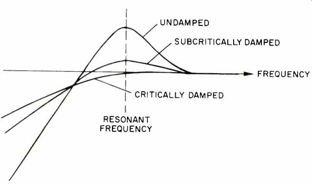
Fig. 16--Effect of bearing damping on tonearm-cartridge resonance.
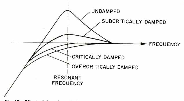
Fig. 17--Effect of damping which "tracks" the record on tonearm-cartridge
resonance.
A typical response curve for an arm with a decoupled counterweight, with suspension tuned to the tonearm resonance, is shown in Fig. 15. There is a major advantage in that the peaks have smaller amplitudes, and at least the higher of the two resonances can be placed at a safe frequency near 15 Hz. The disadvantage is that the lower resonance extends the system response below that of the conventional arm, although damping can be added to prevent this. It can be seen, however, that critical matching between the tonearm, the counterweight, and the cartridge is required for the system to function correctly.
The case where the resonant frequency of the absorber is well below that of the main mass is unlikely to occur, because it implies a counterweight suspended more flexibly than can be tolerated in a practical tonearm.
If the resonant frequency of the absorber is well above that of the mass, the mass will begin to oscillate in the frequency region where the absorber is rigidly connected to the mass. Main resonance effects are therefore unaltered. At the higher absorber resonant frequency, the mass remains still so that no forces exist to move the absorber. The net result is a system identical to the single mass system.
Many tonearms with decoupled counterweights have a stiff rubber suspension, providing a resonant frequency appreciably higher than the tonearm resonance. Such arms are obviously not helped by counterweight decoupling but, in fact, may add to unpredictable and undesired resonances in the audio bandwidth. This is always a danger with any flexible member in a tonearm.
Tonearm Damping
Damping in a tonearm is usually applied at the bearing in the form of a piston moving in a viscous fluid. This form of damping applies a force proportional to the velocity of tonearm movement and opposes the movement. The out-of-phase movement at resonance is reduced at the cost of an extension of response below resonance. This means that the damped tonearm is more difficult to move below the resonant frequency, as shown in the response curves of damped and undamped tonearms of Fig. 16.
Another method is to apply damping between the tonearm and the record. A pad or brush which tracks the record is connected to the rest of the tonearm through a viscous link. If this method is used with a "critical" amount of damping, the tonearm resonance peak is removed without any extension of response below resonance. Critical damping is the amount that is just sufficient to flatten the resonant peak, but not so much as to cause a fall in response curve above the resonant frequency. Response curves for various amounts of damping are shown in Fig. 17.
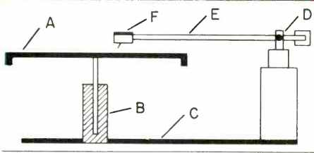
Fig. 18-Possible points of resonance (see text).
Theoretically this is the ideal condition, but in practice it may function less than perfectly. This method is dependent on the tracking of the member resting on the record surface, which can add its tracking forces to those of the stylus and effectively change the tracking conditions for the cartridge. It can also add resonances of its own or alter the frequencies and amplitudes of other resonances, which can be even less desirable.
Other Resonances
In discussing other resonances, it is insufficient to analyze the tonearm in isolation. Extending the argument stated in the introduction, it can be seen that undesirable signals can be generated due to any relative movement between the turntable platter and the tip of the tonearm (the cartridge is still assumed to be perfect). For example if the turntable platter does not run true, it will move up and down for every half-rotation. The effect is the same as a warped record.
Less obvious sources of relative movement are resonances, shown in Fig. 18, in the chain from the platter (A), the spindle and its bearing (B), the bearing support and its connection to the tonearm support (C), the tonearm bearings (D), the tonearm tube (E), and finally the mounting surface at the end of the tonearm (F). No known material, either metal or plastic, is completely rigid, and therefore in physical terms every material always acts like a spring. Rigidity of any component can be increased by increasing the thickness of material used or by using suitable shapes with the same amount of material. Increasing stiffness without altering the distribution or size of the masses raises the resonant frequency but does not affect the amplitude. Each component in the chain has mass, and increasing the amount of material used increases its mass. Increasing mass without altering the stiffness of the components lowers the resonant frequency, but at the same time decreases the amplitude for the same external oscillation force.
Each mass together with the elasticity of the materials in the chain form a resonant system, and, together with other resonances in the system, a complex series of dynamic absorbers, or to use the correct expression, a vibrating system with multiple degrees of freedom.
Conclusion
Provided all the masses and coefficients of elasticity are known (they can be measured or calculated), the resonant system can be analyzed. It should be remembered that the only point of interest is the relative movement between the turntable platter (hence the stylus tip) and the end of the tonearm.
Such an analysis is only the starting point in a tonearm design.
Resonances and other factors can be traded off against each other, and the best design will be the best set of compromises for a particular application.
In the final analysis, the matching of the tonearm to the cartridge and to the rest of the system will play an equally important part in the overall system performance, as will the design of the tonearm itself.
(Audio magazine, June 1980)
Also see:
More Than One Vertical Tracking Angle (March 1981)
Which Tracks Best--A pivoted or a radial Tonearm? (June 1982)