by RICHARD J. KAUFMAN
[Richard J. Kaufman is Consulting Design Engineer for Dennesen Electrostatics, Beverly, Mass.]
Digital audio discs have been available on the market for the past year. These 4-inch discs may well send the familiar 12-inch LP the way of the cylinder and the shellac 78. The praise lavished on this product in the equipment reviews is unparalleled in the history of audio. Radio stations have begun broadcasting CDs, and the response has been overwhelmingly enthusiastic. Has the ultimate sound playback medium been perfected? Definitely not, according to a small group of audiophiles. They object to digital sound as being unmusical, harsh and strident, but they are not taken very seriously (after all, some people claim that tube equipment sounds better than transistors). Yet the claims of these people deserve serious examination. It's often worth pursuing the complaints of an audio minority; in the past, correcting problems the majority didn't hear has led to improvements everyone could hear-once there was a standard of comparison.
Given the general excellence of digital reproduction, it could be that its virtues mask a form of distortion which does not exist in a pure analog medium.
Phase Distortion in Digital Media
Several theories have been advanced to explain the alleged "graininess" of digital sound. The only one that ever seemed to make sense claimed it was caused by phase shift introduced, in recording, by the anti aliasing filter.
The digital sampling rate for most systems is 44.1 kHz; any signal whose frequency is near the sampling rate will cause a form of distortion audible as a spurious tone or "alias," unless the signal is passed through a very sharp cutoff filter. A representative anti-aliasing filter would be an 8-pole Butter worth with a -3 dB point of 22 kHz.
Such a filter does an admirable job of suppressing signals above the cutoff frequency without affecting the frequency response of audible signals.
Response is down 48 dB at 44 kHz, but the phase shift at cutoff is -360°, and it becomes significant above 6 kHz. Figure 1 plots phase shift versus frequency for an anti-aliasing filter.
Other types of filters are also used; some, such as 9- and 11-pole elliptical filters, have group delay characteristics quite similar to those of the sample we've chosen to analyze, especially below 14 kHz. (Additional phase shift is introduced by the noise filter used in playback, but with a well-designed filter, it is slight in comparison to that caused by the anti-aliasing filter.)
The Audibility of Phase Shift
Just because the phase of a signal is altered doesn't mean it is distorted. A phase shift that is a linear function of frequency is equivalent to moving the sound source. The shape of wave forms subjected to a linear phase shift is unchanged when displayed on an oscilloscope. But if you were to display the sum of two tones subjected to a nonlinear phase shift on an oscilloscope, the shape of the signal would be clearly different.
A square wave consists of a series of odd-order harmonics of its fundamental frequency. Thus, a 1-kHz square wave contains components of 3, 5, 7, and 9 kHz and higher. The effect of a nonlinear phase shift on a square wave is to introduce overshoot and ringing, as illustrated in Fig. 2.
Because the harmonics no longer have the proper time relationship to the fundamental or to each other, they no longer sum to a straight line. Any impulse signal (quite common in music) will be similarly affected.
Correcting the phase response will eliminate this overshoot and so increase system headroom. Since even quite powerful amplifiers are frequently driven into brief clipping by digital recordings, even at low to moderate listening levels, any improvement in headroom will improve sound quality.
Low-level portions of the reproduction chain also overload, even during re cording, so the benefits are not limited to playback.
The audibility of phase distortion by itself is another issue. The experimental results that have been published to date have not produced clear-cut results. Apparently, it is audible under some conditions, but to what degree it is tolerable in music-and even how to specify it-is still undefined.
Even though a phase-shifted signal looks different on an oscilloscope doesn't mean it sounds different. Many clearly audible forms of distortion are not visible on a 'scope, and some wildly distorted-looking waveforms sound just fine. In fact, the great 19th-century physicist Ludwig von Helmholtz demonstrated that differences in the relative phase between two sine waves are inaudible.
Music, though, does not consist of pure sine waves. It is made up of many tones that are modulated by complex series of harmonics of other tones Modulated signals are affected by nonlinear phase shift in a manner known as group-delay, or envelope, distortion. Based on my experience designing electrical networks to eliminate group-delay distortion, I believe that an emphasis on group delay rather than on phase shift alone would clarify the issue of the audibility of phase distortion. Such emphasis would also result in a rational standard for its measurement.
A description of group-delay distortion, how it is induced by a nonlinear phase shift, and how it can be eliminated is necessarily involved. The original work that made elimination possible was done at Bell Labs; its practical application prevents computer messages from being garbled going over the phone lines. Adapting these computer line-conditioning techniques to audio has proven to be a fairly straight forward matter. I have tried to keep the accompanying explanations as clear as possible, and hope the reading will prove worth the effort.
The Effect of Nonlinear Phase Shift
Phase delay is proportional to the phase shift divided by the frequency. A sine wave of 11 kHz that is shifted-180° is delayed the same length of time as a 22-kHz sine wave that is shifted -360°. If the phase delay is thus constant at all frequencies, then a complex waveform's shape is not altered, but is merely shifted in time. The difference is not audible. But an 11-kHz sine wave that is phase-shifted by -90° is delayed by 23 compared to 45 uS for a 22-kHz tone shifted-360°. Hence, the two tones would not bear the same relationship to each other after passing through a filter that produced such a nonlinear phase shift.
Group-Delay Distortion
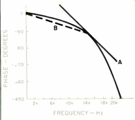
Fig 1--Phase response of an 8-pole Butterworth anti-aliasing filter. At
any given frequency, group delay is represented by line A, which is tangent
to the phase response, and phase delay by line 8, which is between the origin
and the phase response at that frequency.
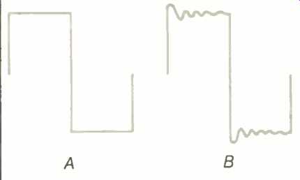
Fig. 2--Square wave before (A) and after (8) phase shift.
Figure 1 is a graph of phase shift versus frequency for an 8-pole Butter worth filter, sometimes used for anti aliasing. Group delay is defined as the derivative of phase shift with respect to frequency; in other words, it is the slope (a line tangential to the phase shift) at a given frequency, as shown by line A in the figure.
Line B represents the phase delay at the same frequency. Phase delay is defined as the phase shift divided by frequency; it is the slope of a line that passes through the origin of the graph and the point representing phase shift at a given frequency.
It is obvious that phase delay and group delay differ. They are identical only when the phase shift is linear. Then, the phase delay is constant at all frequencies, and identical to the group delay.
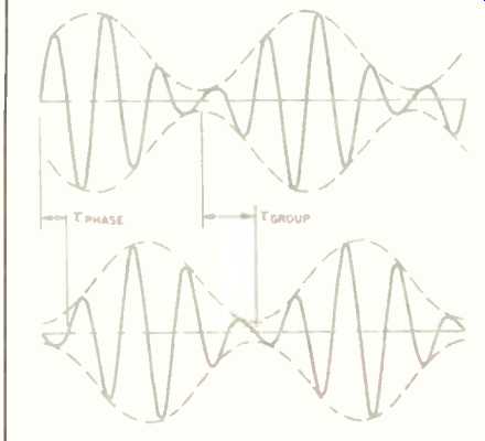
Fig. 3--Envelope distortion: Where phase shift is nonlinear, different
phase-delay and group-delay times cause unequal delay of the carrier
and modulating signal, changing the relationship between them.
The effect of group-delay distortion is shown in Fig. 3. When a lower frequency tone modulates a higher frequency carrier, the carrier is shifted by an amount represented by the phase delay, but the modulating signal is delayed by the time of the group delay.
For this reason the effect is sometimes known as envelope distortion. (It can also be considered as a form of intermodulation distortion.) Voices and the sounds of musical instruments consist of a carrier modulated by a fundamental and its harmonics, and so will be affected by this kind of distortion.
Phase-Correction Networks
All-pass transfer functions have the property of causing phase shift while leaving frequency response unchanged. Ideally, we would like to re- verse the phase shift caused by an anti-aliasing filter without affecting the frequency response, but this cannot be done; the phase shift of an all-pass function can never be complementary to that of a low-pass function, such as an anti-aliasing filter, and so this ideal cannot be realized.
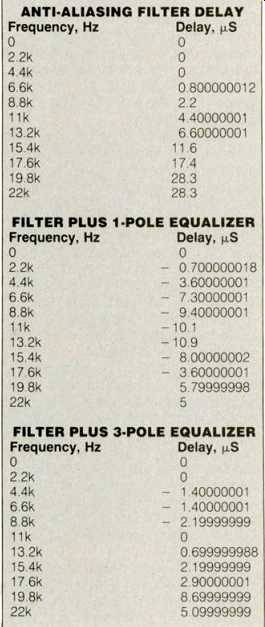
Table I--Group delay vs. frequency for an anti-aliasing filter alone, with
a first-order phase equalizing network, and with a third-order network.
Fortunately, the group delay can be made constant, resulting in an overall phase shift that is linear with frequency. A constant group delay indicates a linear phase shift, and a linear phase shift does not distort a signal.
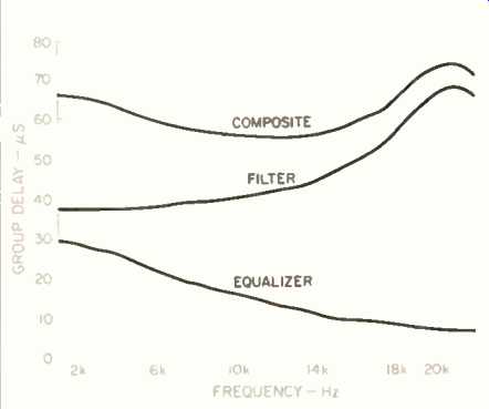
Fig. 4--Group delay of anti-aliasing filter (middle curve); first-order,
all-pass phase-equalizer network (bottom curve), and composite response
(top curve) of filter and equalizer.
Figure 4 illustrates the group delay of an anti-aliasing filter, that of a properly chosen first-order, all-pass net work, and the product of the two. The remaining dip in this response can be further equalized by the use of higher order networks.
Figure 5 shows how an all-pass transfer function can be constructed by means of a summing amplifier. Figure 6 shows an actual, first-order, all-pass circuit to correct the group delay of a digital recording. Use of such a filter produces an audible improvement, as well as a visible improvement in the square-wave (and hence transient) response of a CD or other digitally mastered source. Third-order net works are more complex, and require components and tolerances not generally available to the amateur. (Second-order networks cannot be used alone to correct the phase shift of an anti aliasing filter.) Table I lists the group delay of an anti-aliasing filter, of the filter as corrected by a first-order network, and as corrected by a third-order network. Inspection of these figures shows that, although the first-order network produces a more nearly constant group delay, the variation at certain frequencies is nearly as great as for the uncorrected anti-aliasing filter. A third-order network produces a much more constant group delay, and also sounds better. The use of higher than third-order networks does not seem justified in view of the marginal improvement attainable.
My associates and I have been experimenting with delay equalization of digital media as a means of phase restoration. We have found that both true digital and digitally mastered material are greatly improved by the use of a properly designed delay equalizer. (As one might expect, pure analog material, played through the delay equalizer, sounds peculiar.)
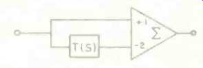
Fig. 5--Block diagram of an active, all-pass filter. Filter T(S) must be
either a first-order high-pass, a first order low-pass, or a second-order
bandpass network.
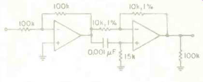
Fig. 6--A first-order, active, all-pass network for correcting group delay
of digital recordings.
The effect is often subtle, but at times dramatic. The difference is most evident with speakers that preserve linear phase relationships, but it is noticeable to some degree on all systems we have tried. Some source material has little information at the higher frequencies, where most of the distortion occurs, but even so there is a greater clarity to the sound, and its location seems more focused. Vocals are more intelligible. Violins sound smoother.
One sound engineer who tried the phase-restoration device said that, at first, the effect seemed so slight he wasn't sure it was important, but after listening with it for several hours, he found he could no longer tolerate the sound of digital material without it.
There is a great deal of variation in digital disc players, as well as in the source material. Some players use a gentle digital filter combined with over sampling to eliminate the glitches present after digital-to-analog conversion; others use a brick-wall filter that introduces as much group-delay distortion as the anti-aliasing filter. We have found that even a partial correction is an improvement, and so both kinds of CD players sound better when used with the same phase-restoration device. Similarly with source material:
A recording may undergo several con versions, digital-to-analog and back again, for it is a usual practice to dump a digital master down to open-reel analog tape for editing (where digital editing facilities are not available) and then reconvert to digital for the finished "master." This will greatly increase the amount of group-delay distortion.
Eventually, I expect all digital recordings to be phase-corrected in the studio-the improvement is well worthwhile. It is possible that advances in digital techniques will make phase correction unnecessary; dbx's delta modulation system uses a very gentle anti-aliasing filter that introduces no phase shift or group-delay distortion below 20 kHz. Perhaps the next generation of CD players will include phase-restoration devices. Even if the effects of group-delay distortion weren't sonically objectionable, the lessened incidence of clipping, due to increased system headroom, would justify the use of a delay equalizer. In the mean-time, an add-on phase restoration device is necessary to realize the full potential of digital recordings.
---- ON THE TEST BENCH ----
My measurements on the Dennesen phase-correction device, designed by Mr. Kaufman and Peter Madnick, show the following:
Frequency response extends to d.c. for both channels. In the bypass position, both channels are flat within ± 0.02 dB to 30 kHz. With phase correction, both channels have a slight rise at 30 kHz (0.35 dB for the right channel and 0.25 dB for the left); within the audio band, frequency variations are negligible. The differences between the left and right channels are 0.08 dB of amplitude and 0.34° of phase at 20 kHz, with smaller differences in the audio range.
Group delay is 39 µS at 20 kHz. Group delay does not dip at 20 kHz, as would be expected for complete compensation of a sharp-cutoff, 20-kHz, anti aliasing filter. This implies a partial rather than a complete correction over the audio band. As the only anti-aliasing filters I had available for test do not cut off at 20 kHz, I could not perform a cascade response. The Dennesen group delay is in the correct direction to provide compensation, but I cannot positively say how effective it is. The Time Delay Spectrometry gear showed residual error of less than ±0.05 dB peak-to-peak. ±0.01 dB average, due to system noise in the 50-Hz tracking bandwidth.
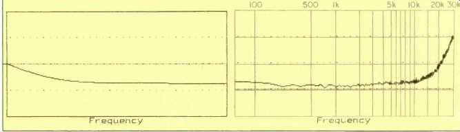
Phase vs. frequency, high-frequency time delay removed. (Vertical scale:
45°/division; horizontal, 9053.48 Hz/inch.); Output vs. frequency. (Vertical
scale: 0.2 dB/division.)
-Richard C. Heyser
(adapted from Audio magazine, Jul. 1984)
Also see:
Philips Oversampling System for Compact Disc Decoding (April 1984)
Error Correction in the Compact Disc System (April 1984)
Music of the Bitstream (Jan. 1991)
= = = =