By Martin Clifford
EVERY HOME has a crying need for storage space, with the housewife usually doing most of the crying. An analogous situation exists with FM components, such as tuners, receivers, and amplifiers, for the concept that electric currents must be continuously on the go is quite erroneous. There are times when it is necessary to store a voltage, thriftily squirreling it away for later use.
It would also seem, in this context, that voltage and current are used synonymously. A current consists of the movement of electrons, each carrying a negative charge. Stop this flow of current to allow the electrons to accumulate on some conducting surface, such as a metal plate, and you have a voltage. The electrons, now in a static condition, strain to be off elsewhere, to distribute themselves from a crowded to a much less so condition. This effort, also known as electromotive force (or emf), or potential difference (or PD), or voltage, exists between any area having a multiplicity of electrons and any adjacent, less electron-packed region. Once the electrons are allowed to move, we have an electric current. And so electrons supply both voltage and current.
Electronic high-fidelity components pose a three-part problem: 1. to generate a voltage; 2. to let various currents flow along designated paths, and 3. to store electrons as the circuit and occasion require. Any battery or generator can produce a voltage; any conductor can supply an easy path for the movement of current. The problem, then, is how to store electrons.
The problem of generation, transmission and storage isn't new, for it has existed since the beginning of electricity as a science. Oddly enough, early experimenters in electricity solved the difficulties of transmission and storage first, while the generation of voltage came in a poor third.
The First Electron Storage Concept
The first device for the storage of electrons was a glass bottle, partially filled with water. The bottle had an insulating stopper and coming down through this stopper was a metal rod, just long enough to reach slightly below the surface of the water. The remaining element of this contraption, called a Leyden jar, was human fingers wrapped around the bottom part of the jar. And this was the inelegant ancestor of one of the essential parts you will find in high-fidelity components-the capacitor.
The human body with its various extremities is an electrical conductor. So is water, provided it is contaminated, preferably with some kind of acid, base or salt. Fortunately, the original inventors of the Leyden jar were more concerned with electricity than with water quality. Pure water isn't a conductor. How strange to think the capacitor might not have been discovered if its inventors had worked in a scrupulously clean laboratory.
The Leyden jar, invented by Ewald Georg von Kleist, at one time Dean of the Cathedral of Kamin in Pomerania was also invented independently by Professor Pieter von Musschenbroek of the University of Leyden, in Holland, about 1745. Subsequently, this primitive capacitor was improved by surrounding the lower portion of the jar with a metallic coating, while the water was replaced by iron filings. Finally, one investigator, Dr. John Bevis, came to the conclusion that the shape of the Leyden jar had no influence on its behavior and used a flat section of glass coated with tinfoil on both sides.
The Leyden jar is a museum curiosity but the Bevis arrangement would be recognized today as a capacitor. When he wasn't busy flying a kite, inventing the lightning rod, or the Franklin stove, fomenting a revolution, or developing the concept of positive and negative in electricity, Benjamin Franklin meticulously and methodically studied the behavior of the Leyden jar and correctly concluded that the positive charge on one side of the glass was equal to the negative charge on the other side. He also discovered that the amount of charge could be increased or decreased by varying the thickness of the glass and the areas of the conducting surfaces, basic concepts still valid in the manufacture of capacitors. And so, even if indirectly, Franklin made a substantial contribution to high-fidelity electronics.
The Charged Capacitor
The ancestral capacitor consisted of two sheets of metal separated by glass. Glass is an insulator, a non-conductor of electricity, and in its position in a capacitor is called the dielectric (Fig. 1). Modern capacitors use just about anything and everything that will not conduct as a dielectric: paper, mica, ceramic materials such as titanium dioxide and barium titanate, mylar-coated paper, thin plastic film or thin oxide film, bakelite, castor oil and mineral oil.
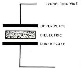
Fig. 1--The basic capacitor consists of a pair of metal plates and a non-conducting
dielectric.
When connected across a d.c. voltage (Fig. 2) the relatively substantial plate area of the capacitor represents an unexcelled opportunity for the electrons crowded on the negative terminal of the battery to migrate. The voltage source can also be a d.c. generator or the d.c. output of a power supply. To the capacitor the voltage source is an electron source. To the voltage source, the capacitor represents a chance for electrons to get away from it all. And so there is an electron movement from the voltage supply onto the capacitor plate connected to the minus terminal.
But the electrons are now trapped in a cul-de-sac, a dead end. Having arrived at the capacitor plate, there is no place for them to go. The nearest available area is close by but is blocked off by a glass plate.
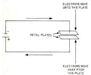
Fig. 2--Electrons move from the negative terminal of the voltage source to
one of the metal plates of the capacitor. An equal number of electrons leave
the other plate and move to the positive terminal of the battery. This electron
displacement charges the capacitor.
In the meantime electrons originally resident on the other plate are repelled by the nearby presence of the newly arrived electrons on the other side of the glass, and so they in turn escape to the positive terminal of the battery.
We now have a condition in which one plate has an electron excess, while the other has an electron shortage.
Consequently, there is a pressure between the two plates caused by this electron imbalance, more technically known as a voltage. At the moment the capacitor was connected across the terminals of the battery, the capacitor voltage was zero. With the movement of electrons onto the capacitor plate, the pressure between the plates increases until it becomes equal to that of the electron-supplying voltage source. No further electron movement takes place, the electrons on the capacitor plate firmly opposing any further movement from the source. The voltage across the capacitor and that of the source are now equal. The capacitor is fully charged.
Electron Storage
Electrons are now stored on one plate of the capacitor. They can be led away by connecting conductors to the capacitor plates, possibly to some circuit or part. The point is that the electrons will remain where they are until required. The capacitor is an electron reservoir.
Amount Of Electron Storage
Storage implies capacity. In terms of capacity, a gallon of wine is superior to a fifth of Scotch. Similarly, some capacitors are designed to hold or store a relatively small number of electrons; others are intended to pack away huge quantities. The amount of storage is a function of the work to be done by the capacitor, leading to such gem-like cliches as "never send a mica capacitor to do the work of an electrolytic." The basic unit of capacitance is the farad, named in honor of Michael Faraday (1791-1867). Unfortunately, the farad is an enormously large unit, somewhat akin to a 10,000-acre ranch being seriously proposed as a modest back garden for a four-room cottage.
A more realistic unit is the microfarad, or one-millionth of a farad. A most unlikely capacitor having a capacitance of one farad could be replaced by a million capacitors each having a rating of one microfarad. And even the micro farad is sometimes too large, for it, in turn, could also be replaced by a million capacitors each having a value of one picofarad. A picofarad is one-millionth of a microfarad which, in turn, is one millionth of a farad. A most nonsensical way of designating capacitance, but there it is. The only order in this semantic chaos was the recent substitution of picofarad for micro-microfarad.
Picofarad and micro-microfarad are synonymous, with picofarad as the preferred word. Still another gain was the replacement of capacitor for condenser, the original name selected for this unit. Condenser was replaced by capacitor when engineers realized that a pair of metal plates separated by a dielectric didn't condense anything. That took quite some time, though.
Abbreviations For Capacitance
The abbreviation for farad is F. For microfarad it is µF with the Greek letter mu as the substitute for micro. Logically, micro-microfarad would be µµF, but the preferred designation is now pF. To compound electronic confusion, you will sometimes see µF written as mf, mF, mfd, MFD, µfd, or other variations. Similarly with µµF. Capacitance Conversions It's easy enough to convert from one unit of capacitance to another since it's just necessary to divide or multiply by a million. The trick is to remember your direction, for if you go the wrong way the error is a beaut.
To change farads to microfarads, multiply farads by a million. To change microfarads to picofarads, multiply microfarads by a million. Divide if you want to move the other way. To change picofarads to microfarads, divide microfarads by a million. And to go from microfarads to farads, divide microfarads by a million. The easiest way to divide or multiply in the decimal system is to move the decimal point to the right or left the required number of places (Fig. 3). Sound difficult? It just needs a little practice.

Fig. 3--Conversion from microfarads to picofarads, and vice versa, is more
easily accomplished by moving the decimal point.
Capacitor Designations
Capacitors are not only identified by the amount of capacitance but by some physical characteristic as well. A mica capacitor is so called because its dielectric is mica; a silver mica capacitor uses a silver plating on the dielectric in lieu of plates; a disc capacitor has a disc-like shape; a paper capacitor has a paper dielectric.
Capacitors are sometimes named for the work they do: a bypass capacitor will bypass or supply a detour for unwanted signals. Some names used in connection with capacitors are meaningless unless you are circuit-wise: filter capacitors, neutralizing capacitors, padders, all relate to electronic functions in particular circuits.
Working Voltage
A voltage is pressure and the ability of a capacitor to withstand that pressure is known as d.c. working voltage, abbreviated DCWV. A capacitor rated at 100 DCWV means the capacitor should be able to tolerate this amount of pressure. The working voltage of a capacitor depends on how the capacitor is manufactured, and on the ability of the capacitor dielectric to deny passage to the electrons crowded on one side of it. Generally speaking, the higher the DCWV of a capacitor, the more it costs. A very low-priced tuner or amplifier may use capacitors having marginal voltage ratings. A quality component will use capacitors having substantial d.c. working voltage margins.
Color Codes For Capacitors
Color codes are used to indicate the amount of capacitance for paper, mica and ceramic units. Colors are also used to indicate d.c. working voltage, tolerance, temperature coefficient, and capacitance drift. (Fig. 4 through 7). Color coding always refers to capacitance in pF. Unfortunately, there are quite a number of different color coding arrangements, and, in some instances, all information regarding a capacitor is completely omitted. Capacitors can be so small that information color coding is impractical. Sometimes capacitors are made for specific applications by manufacturers and since the capacitors aren't intended for commercial sale they won't be marked or else will be marked by a special code designed by the manufacturer. When a capacitor is large enough, the information may be printed on it (Fig. 8). At one time in the electronics industry, capacitors and resistors had distinctive shapes and so it was always easy to distinguish between them. But with an increasing variety of resistors and capacitors and with miniaturization of these parts, plus absence of coding, it is often difficult to determine when a part is a resistor or a capacitor without the use of test instruments.
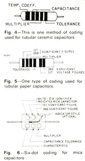
Fig. 4--This is one method of coding used for tubular ceramic capacitors.
Fig. 5--One type of coding used for tubular paper capacitors.
Fig. 6--Six-dot coding for mica capacitors.
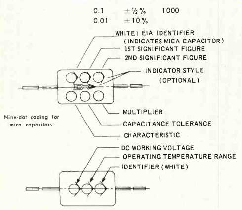
Fig. 7--Nine dot coding for mica capacitors. Both sides of the capacitor are
used in this coding system.
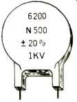
Fig. 8--If the surface area is large enough, the data is printed directly on
the body of the capacitor.
Dielectric Constant, K
The amount of capacitance of a capacitor depends on the total area of the plates, the kind of dielectric used, and the separation of the plates. The larger the plate area, the greater the capacitance, and the closer the plates are to each other, the greater the capacitance.
The effect a dielectric has on capacitance is known as its dielectric constant, represented by the letter K. Air has a K of 1, but if mica is inserted between the plates of the same capacitor, its total capacitance may be increased as much as 5 to 7 times. Mica, then, has a K of 7. Some ceramic materials have a K of several hundred, giving manufacturers an opportunity to pack a tremendous amount of capacitance in a small space.
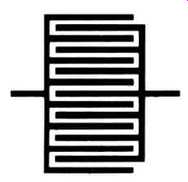
Fig. 9--To increase total capacitance a number of plates may be used.
Various techniques are used to increase plate area (Fig. 9). A number of plates may be used, with all plates on one side of the dielectric connected and all plates on the other side similarly joined. Thus, a capacitor with a large number of plates may have just two connecting leads. Another method is to etch the plate area to make it rough rather than smooth, increasing surface area. And in some capacitors the plates are made of extremely thin aluminum foil. A fairly long roll occupies little space.
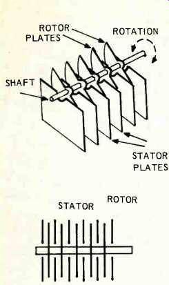
Fig. 10--A variable capacitor consists of a number of fixed plates, all connected,
called the stator. The rotor plates are mounted on a shaft which can be turned.
Fixed and Variable Capacitors
Fixed capacitors are those whose plates are firmly positioned and cannot be changed. A variable capacitor, as its name implies, is one whose capacitance can be altered easily and smoothly by varying the position of one set of plates (the rotor) with respect to the other (the stator) (Fig. 10). These capacitors, used for tuning the front ends of tuners or receivers, most often have air as the dielectric, but other dielectrics have been used. Variable capacitors use a set of rotor plates mounted on a shaft controlled by a knob from the front of the tuner or receiver. A number of variable capacitors can be mounted on a common shaft so that a single turning effort will rotate the plates of two, three or more capacitors. Thus, the rotor plates can be used to tune either one or several circuits simultaneously. With two or more variable capacitors mounted this way, the unit, known as a ganged capacitor, will have a set of stator plates for each rotor.
A three-gang capacitor is really three individual capacitors linked by having a common rotor. In a receiver such a capacitor could be used to tune the radio-frequency (RF) amplifier, the local oscillator, and also the mixer. In the early days of radio, prior to the invention of the ganged variable capacitor, these circuits had to be adjusted individually, and so those early sets had three tuning dials, not one.
Another type of variable capacitor is the setscrew adjust type used where a fairly precise amount of capacitance is required. Once the correct amount of capacitance is obtained, no further adjustments are made, and the capacitor then functions as a fixed unit. In receivers and tuners these are quite critical and are factory adjustments.
It is highly inadvisable to change their settings without considerable know-how backed up with adequate test instruments.
Electrolytic Capacitors
Sometimes very high values of capacitance are required. One type, specifically designed to supply this need is the electrolytic, differing from the others in the dielectric used and in the plate material. Essentially, an electrolytic capacitor consists of long rolls of very thin aluminum foil of high purity separated by an electrolyte such as boric acid. During manufacture the capacitor is placed across a d.c. voltage and in this process an extremely thin film of oxide is formed on the surface of the foil connected to the plus terminal of the charging source.
Because the oxide film is so extremely thin, the aluminum foil plates are remarkably close to each other. To increase the capacitance, the foil plates may be etched to increase the surface area. These features, plus the fact that the aluminum foil is extremely thin, permitting long lengths of it to be rolled up inside the capacitor housing, result in large amounts of capacitance.
Unlike other capacitor types, electrolytics are polarized; they are marked with plus and minus signs. The plus terminal of the electrolytic is connected to the plus terminal of a voltage source and the negative terminal of the capacitor must be wired to the minus side of the voltage.
Electrolytics are generally larger than other capacitor types and so data color coding isn't used. Instead, the information is printed directly on the capacitor case. Basically, this consists of the capacitance, the d.c. working voltage, and plus-minus symbols to indicate the polarity. Sometimes two or more electrolytics are mounted in a single case, with identifying symbols on the case to indicate each capacitor.
Capacitor Leakage
Capacitors at work in high-fidelity systems are subjected to a variety of stresses and strains, all calculated to reduce their effectiveness, resulting in a variety of troubles easily placed under one heading-sound degradation.
Capacitors may be exposed to high temperatures inside high-fidelity components, or to humidity. Every capacitor, of course, must endure the strain of receiving electrons and losing them. Transient voltages, voltages far in excess of normal operating conditions, can cause a capacitor to lose some of its electron storage ability. Dust accumulating between the capacitor terminals can add its mite to the capacitor's less-than-pleasant working conditions. And finally, tiny impurities in the dielectric may represent potential weak spots.
Capacitor leakage, as its name implies, means that some of the electrons stored on one of the plates, manage to find a path through the dielectric to the other plate. Insofar as the electrons are able to do this they are no longer available as storage electrons, meaning that some circuit dependent on the capacitor for its electron supply will not receive the required amount. The effect in a hi-fi system may not be noticed or may be highly annoying, depending on the seriousness of the leakage and the number of capacitors engaged in this activity. Some capacitors have higher leakage characteristics than other types. Electrolytics have this disadvantage because of the extremely thin dielectric used and also because such capacitors are frequently subjected to very high potentials.
Leakage is minimized by using dielectrics of greater purity, by sealing the capacitors so thoroughly that no moisture can possibly enter, making them impervious to humidity, and by strict quality control during manufacture. Quality capacitors aren't to be found in bargain basements.
Capacitor Types
Capacitors are available in just about every conceivable size, shape and style (Fig. 11). Physical size may be of importance to a manufacturer in the construction of high-fidelity components for it is sometimes necessary to pack a tremendous number of parts into a limited space. Replacement of a capacitor in a high-fidelity component, then, means not only strict attention to such factors as capacitance, tolerance, leakage, and working voltage, but to physical size as well. A replacement capacitor must be able to fit into the space allotted to it.
Capacitor Symbols
Various symbols are used in schematic diagrams for fixed, single variable, ganged variable, and electrolytic capacitors. The basic symbol is a pair of lines, one of which is slightly curved, although you will find some capacitor symbols using a pair of straight, parallel lines. The variable capacitor is identified by an arrowhead placed on one of the lines while a ganged variable is represented by a dashed line to indicate simultaneous operation of both rotors of the ganged unit. The symbol for an electrolytic is often marked with a plus sign to indicate that this unit is polarized.
Other information may or may not be marked alongside the capacitor symbol. Sometimes the amount of capacitance is marked adjacent to the capacitor symbol, but it is necessary to understand whether this number represents microfarads or picofarads. Quite often this information is not supplied, since it is expected that the person reading the diagram will have sufficient circuit knowledge to know what value of capacitance is intended. As a general rule, capacitance values on circuit diagrams are understood to be in microfarads. The number .01 adjacent to a capacitor would indicate 0.01 microfarads. However, capacitance values in picofarads would be marked as such. Thus, 20 pf means 20 picofarads.
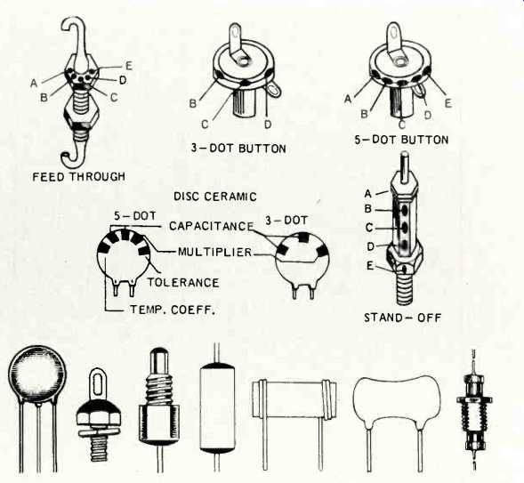
Fig. 11--Capacitors are available in a tremendous variety of sizes, shapes
and styles. The letters adjacent to the capacitors indicate color-coded dots
which supply data.
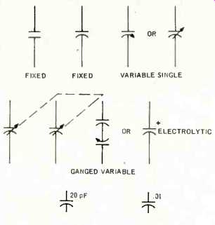
Fig. 12-Capacitor symbols.
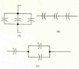
Fig. 13-Capacitors can be connected in parallel (A), in series (B), or in
series-parallel (C).
Increasing and Decreasing Capacitance
Capacitors may work alone or in combination with other capacitors, depending on circuit requirements. When two capacitors are placed in shunt, or parallel (Fig. 13-A), the total overall capacitance is increased and is equal to the sum of the individual capacitances. Generally, only capacitors having identical d.c. working voltage ratings are connected in this way. However, this restriction does not apply to capacitance, for a unit having a large capacitance may be parallel-teamed with one having a miniscule amount.
Capacitors can also be wired in series, but this reduces the overall capacitance (Fig. 13-B). This method is sometimes used to reduce electron storage capacity in a particular circuit or to increase the d.c. working voltage. The d.c. working voltage of the series connection is equal to the sum of the d.c. working voltages of the individual capacitors. Sometimes series-parallel combinations are used to supply both a higher working voltage and a higher capacitance.
Capacitors and Resistors
Paraphrasing John Donne, no capacitor is a component unto itself. They are quite often used in combination with other electronic parts, such as resistors. A resistor in series with a capacitor will slow the rate at which electrons pour into a capacitor plate. Sometimes, in an electronic circuit, it will be necessary for a capacitor to charge, or to discharge, within a set time limit. Resistors are also placed in shunt with capacitors in some cases to discharge the capacitors within a specific time after they have been charged.
Jobs Capacitors Can Do
Like resistors, capacitors have a variety of interesting jobs to handle in hi-fi equipment. They can be used to separate currents of different frequencies. They can be used to deny the passage of some currents and to permit the flow of others. They can be used to smooth currents when these currents contain unwanted variations. And, of course, you use them every time you turn on your tuner or receiver to select a station.
( Audio magazine, Aug. 1972)
Also see:
The Language of High Fidelity--Part IV: Basic Electronic Components (concl.) (Sept. 1972)
The Language of HIGH FDELITY: Part II--Basic Electronic Components (Jun. 1972)
The Language of High Fidelity--Part VII: The Basic High-Fidelity System (Dec. 1972)
The Language of High Fidelity--Part VIII (Feb. 1973)
Language of High Fidelity--Part XI (May 1974)
= = = =