Manufacturer's Specifications
Number of Tuned Circuits: Three (LC).
Tuning Range: 87.5 to 108.5 MHz.
R.f. Gain: 30 dB.
Noise Figure: 4.0 dB maximum.
Bandwidth: 600 kHz.
Variable Gain Control Range: -10 to +30 dB.
Input/Output Impedance: 300 ohms.
Power Requirements: 120 V, 50/60 Hz, 10 watts max.
Dimensions: 8 1/4 in. (20.96 cm) W x 3 3/4 in. (9.53 cm) H x 7 1/2 in. (19.05 cm) D.
Weight: 4 lbs. (1.8 kg).
Price: $159.95.
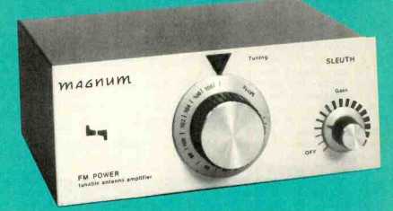
Magnum Electronics, Inc. is a company located in Toronto, Ontario, which has been specializing in the manufacture of r.f. amplifiers such as the 95FM Sleuth since 1976. This amplifier or "booster" is distributed by the same firms who handle the GAM Stereo One FM antenna. The 95FM Sleuth can be used with any FM antenna, however, with the choice of antenna type and gain dependent upon location, terrain and the other factors which normally determine the type of antenna to be used with FM sets.
The circuitry of the 95FM amplifier is contained in a steel chassis and housing. The front is augmented with a solid aluminum panel having only two controls. A tuning control at the center of the panel is calibrated in approximate 1-MHz steps, from 88 to 108 MHz. A smaller rotary knob, at the right lower corner of the instrument, serves the dual purpose of turning the amplifier on and off and of varying its r.f. gain. The rear panel of the 95FM is equipped with 300-ohm input and output terminal pairs. The terminals used are of the "push to insert wire ends" type, which I found to be a bit inappropriate, since many supplied dipole antennas come equipped with spade-lug terminals that are meant to fit under the heads of screw terminals. A lug can be fitted into the terminal or, better, the leads stripped by hand in order to connect them properly to the type of terminal incorporated in the 95FM. There is no provision for direct connection of 75-ohm coaxial cable, so that if this type of transmission line is used it is necessary to employ a matching transformer of the type commonly used in hooking up antenna cables to video recorders, etc.
The manufacturer of this r.f. amplifier has sealed its electronics inside its enclosure with a Robertson screw which defied my best intentions (and tools) to loosen. Therefore, all I can tell you about the circuitry is what the manufacturer tells in the owner's manual, namely that there are three stages of tuned circuitry (LC types) and that the transistors used in the amplification stage are low-noise MOS Field Effect types. Beyond that, I had to rely on my lab test results for any indication as to the effectiveness of the circuitry.
Measurements
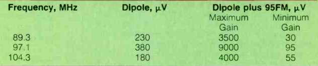
Table I--Signal strength readings with and without the Magnum 95FM antenna
amplifier.
I decided to use a standard half wave dipole as a reference antenna for testing the Magnum 95FM Sleuth. A field strength meter was tuned to incoming signals at the low, middle and high ends of the FM dial, using identifiable station signals. Field strengths for these signals, obtained using only the dipole antenna, were recorded. Then, the Magnum 95FM amplifier was interposed between the antenna and the field-strength meter. The short length of 300-ohm twin-lead supplied with the unit was used to connect from the amplifier output terminals to the field strength input (via a 300/75-ohm transformer needed to match the input impedance of the field-strength meter). Signal strength readings were then observed for the same three incoming signals at maximum and minimum gain settings of the 95FM amplifier's gain control. Results are tabulated in Table I. Note that the range of gain is very nearly 40 dB, exactly as claimed by the manufacturer. Of significance, too, is the fact that with the gain control set at minimum, it is possible to attenuate incoming signals by approximately 10 dB. This feature may prove to be just as useful as the positive gain aspects of the device, since in many situations, overload of a front-end (in close-in areas) can be just as annoying a problem as inadequate signal strength.
In FM reception, signal strength alone does not determine ultimate audio quality. Most "boosters" I have tested in the past, while amplifying the incoming signal strength (in absolute microvolts or dBf), tend to amplify noise levels as well. That was not the case with this amplifier, which boasts a very low internal noise figure of its own. My listening tests, which followed the measurements described above, indicated that much of the available gain of this device was translated usefully into a quieter, better-sounding audio program signal for my reference tuner in the lab as well as for two other tuners which were on hand when these tests were conducted.
The extra tuned circuits contained in this amplifier serve to improve the effective adjacent and alternate channel selectivity of any tuner or receiver with which it is used. While it would be difficult to determine the exact increase in alternate channel selectivity afforded by the device (among the variables here are the tuner with which the 95FM might be used), I would estimate the improvement in alternate channel selectivity as being between 10 and 15 dB--not an insignificant amount for this important specification.
If you are having problems with weak signal FM reception (and are already using a decent outdoor FM antenna) or with alternate channel interference, the Magnum 95FM amplifier might well be worth a try.
-Leonard Feldman
(Audio magazine, Aug. 1982)
Also see:
Magnum Dynalab FT-101 tuner (Jun. 1986)
TERK 8403 FM Antenna (Equip. Profile, Jan. 1986)
Terk Technologies Model Pi2 FM Antenna (Nov. 1990)
Antennas FM -- Try a Rhombic FM Antenna (Jan. 1982)
Kill FM Interference With Two Antennas (Jan. 1980)
FM Fidelity: Is The Promise Lost? (March 1985) and The Problem with FM (March 1985)
= = = =