by M. J. SALVATI
Feeding low bass to subwoofers brings your system several advantages; using a single, center channel subwoofer brings a few more. The electronics needed for this are easy to build, and can be used with either a mono or a stereo power amp.
In conventional systems, the right and left-channel speaker systems must usually be either large or inefficient-and usually expensive-to get low bass. It's not always possible to place speakers (especially large ones) so as to achieve both optimum bass and optimum stereo imaging; it's also hard to design speaker cabinets for both low-bass output and optimum high-frequency dispersion.
With the lowest tones directed exclusively to subwoofers, it does not matter if the right- and left-channel speakers have poor performance at those frequencies. Relatively small, full-range speakers, having excellent sound (from, say, 100 Hz up to 20 kHz), can be part of a first-class sound system despite their low-bass deficiencies.
Those speakers can also be placed without regard for the effect on low frequency reproduction-for instance, off the floor for more natural imaging and better dispersion. Only the woofer need be placed with bass in mind, and it can often be out of sight for aesthetic reasons.
With a subwoofer, distortion often becomes lower. If the subwoofer is fed from its own amp, distortion products from the bass cannot affect the mid range and treble, which are powered separately. By eliminating low-frequency input to the main speakers, the chance of interfering with (or even damaging) high-frequency and mid-range reproducers in poorly sealed en closures is eliminated.
Using a single woofer for both channels adds some more advantages First, a single woofer is easier to place (and to afford). Second, a center-channel woofer can reduce (or, some feel, eliminate) turntable rumble. The stylus motions produced by rumble are primarily vertical, producing equal but oppositely phased rumble components in each channel. In the usual stereo system, the rumble sound output from the right and left speakers will not cancel completely, due to inter channel phase shifts and acoustic factors, and so can be heard. Even if inaudible, they make the speakers and amplifiers work harder (sometimes contributing to distortion from other causes). With a single, center-channel woofer, nearly all rumble is cancelled.
Lastly, if only one big woofer and en closure are required, you can get a bigger and better model for the space and money available.
If any of these advantages appeal to you, read on. This article describes the construction and use of the crossover filters and bass-summing mixer needed to implement a center-woofer sys tern. This particular implementation operates between the preamp and power amplifiers (Fig. 1A), rather than between the power amplifier and speakers. This has several advantages. The mixing and crossover are made at negligible power levels, avoiding the huge and expensive components normally required for a very low crossover frequency, and the subwoofer can be driven directly by its own power amplifier. This results in a high damping factor for the woofer, and no loss of separation between right and left channels or interaction between speakers.
=========
Table 1--Specifications.
General:
Crossover Frequency: 100 Hz (selectable, see text).
Input Impedance: 100 kilohms r channel.
Output Impedance: 100 ohms per channel.
Input/Output Level: 1 V rms typical, 5 V rms maximum.
Power Requirements: 110 to 130 V a c 3 VA t p
Center Channel
Passband: 100 Hz, -3 dB.
THD at 1 V rms: Less than 0.015% at 20 Hz
S/N Ratio, 10 Hz to 10 kHz: 120 dB below 1 V rms
H.f. Roll-Off Rate: 12 dB/octave.
Maximum Output Level: 8 V rms
Right and Left Channels
Passband: 100 Hz (-3 dB) to 150 hz.
THD at 1 V rms: Less than 0.006% at 500 Hz, less than 0.015% at 20 kHz.
S/N Ratio, 10 Hz to 20 kHz: 114 dB below 1 V rms
L.f. Roll-Off Rate: 12 dB/octave.
Maximum Output Level: 6 V rms at 20 kHz, 1 V rms at 100 kHz.
=========
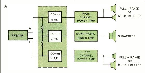
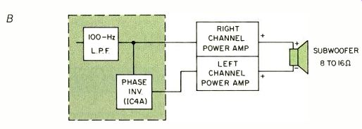
Fig. 1-System connections for center-channel woofer, using monophonic amplifier
(A) or stereo amplifier (B) for center channel.
Notice that the basic setup (Fig. 1A) uses a monophonic power amplifier to drive the center-channel subwoofer. If you do not have a suitable mono power amplifier, no problem; Fig. 1B shows how to connect a conventional stereo power amplifier to drive the center woofer. A built-in phase inverter drives one channel of the stereo power amp, so the subwoofer can be differentially connected across the R and L output terminals to use the power of both amplifier channels.
The crossover is compatible with all standard preamps, power amps, integrated amplifiers, and receivers. The only requirement (of receivers and integrated amplifiers) is that the preamp/ power amp chain can be broken for insertion of the device. As Table I shows, there will be no degradation of even the finest sound system when using this device. In fact, the distortion levels indicated are actually the residual levels of my test equipment.
The optional voltage monitor will flicker yellow when high-amplitude, sub-bass tones pass through the crossover unit. If a d.c. breakdown occurs, it will glow steadily (red for a positive fault voltage, green for a negative fault voltage).
Theory of Operation
This crossover network divides the stereo signal frequencies, providing a derived center-channel signal consisting solely of low bass, and right and left channels consisting of upper bass through treble. The frequency division is done prior to power amplification. A phase inverter stage is also provided so that a standard stereo power amplifier can be used as a center-channel monophonic power amplifier. The schematic diagram is shown in Fig. 2.
R and L Channels. Op-amp IC1A is a unity-gain buffer that provides a high input impedance for the right channel, and a low output impedance to drive the filter and mixing matrix. Op-amp 101B is configured as a two-pole, high pass filter with a 12 dB/octave roll-off and a fairly sharp corner. The values of resistors R12 and R13, and capacitors C1 and C2, set the-3 dB corner frequency (see Table III). The low output impedance of IC1B enables it to drive power amps with very low input impedances. Op-amps IC3A and IC3B, and R14/R15/C5/C6 perform the same functions for the left channel.
Center Channel. Resistors R2 and R3 form a mixing network that combines right- and left-channel signals to produce a derived monophonic or center-channel signal. Op-amp IC2A is a unity-gain buffer/driver for the low pass filter consisting of op-amp IC2B and R4/R5/C3/C4. Like the filters in the left and right channels, this two-pole filter has a 12 dB/octave roll-off and a fairly sharp corner. Op-amp IC4A is a unity-gain inverter that provides an output signal at C(L) jack J5 that is equal in amplitude but opposite in phase to the output signal at C(R) jack J4.
Op-amp IC4B is a voltage sensor that lights LED D3 if a significant d.c. voltage appears at either of the bass output jacks (J4/J5). This provides visual warning of a malfunction in either the preamp driving this crossover unit, or op-amps IC1A, IC3A, IC2, or IC4A.
Construction Notes
To get the highest possible S/N ratio, do not route the power transformer's wiring near the circuitry or connectors, and mount the transformer as far from the circuit board as your enclosure permits. For example, you might bolt transformer T1 to one end of a minibox, and use the opposite end to mount connectors J1 through J6.
Choice of Parts. There is considerable latitude in the ratings for some of the parts listed in Table II. For example, the low-power (100-mA, TO-92 case) versions of voltage regulators 105 and IC6 will do nicely, although the equivalent higher power versions listed will work just as well. Similarly, any ceramic capacitor having a voltage rating over 20 V and a capacitance range of 0.02 to 0.1 uF can be used for C7 through C14. The most important consideration for these bypass capacitors is to locate them physically close to their associated ICs.
Although 10%-tolerance capacitors and 5% tolerance resistors can be used for the filter networks, crossover accuracy may be improved by using high-stability, 5% capacitors and 1% metal-film resistors. (Both 1% and 5% resistor values are given in Table III.) The RC4739 (101 through IC4) is a dual op-amp specifically promoted as a low-noise amplifier. The RC4136, RM4136 and RV4136 made by Raytheon and by Texas Instruments have identical circuits and specifications.
These, however, are quad op-amps in 14-pin packages, so the pin connections are different from those of the 4739, and the parts layout will be more difficult. Still, if you have trouble obtaining the 4739, the 4136 can be used; one for the R and L channels and one for the C channel and sensor. Just be careful in laying out the parts for the R and L channels, to avoid coupling.
The "B" and "Y" adjacent to LED D3 in Fig. 2 refer to the color-coding of the IDI 5100H1/5 leads. If you use a different LED, connect it so that pin 13 of IC4B gets the lead that produces a red glow in D3 when a negative current is applied to it.
Options and Modifications. To further reduce the amount of very low bass reaching the R and L speakers, you may wish to add capacitors in series with the R and L outputs (J3 and J6 respectively). These capacitors introduce additional roll-off, with a 30-Hz,-3 dB corner. Their value depends on the input impedance of the R/L power amplifier; typical values are 0.5 uF for 10 kilohms, 0.2 pl for 25 kilohms, 0.1 uF for 50 kilohms, and 0.05 uF for 100-kilohm input impedance. These capacitors will also protect main-channel power amplifiers with d.c. input coupling in the event of a d.c. breakdown of IC1B or IC3B. If your power amplifier is a.c.-coupled, it is probably not worth bothering with these additional capacitors.
The voltage sensor (IC4B and bipolar LED D3) for the center channel is just a bit of fluff added to "use up" the spare op-amp. If your crossover device is located where you can't see the LED, or if you simply do not want to bother with it, feel free to omit D3 and R17.
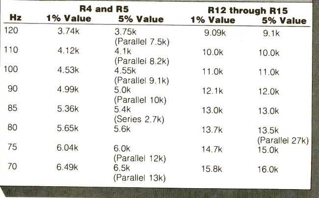
The crossover frequency specified in Table I is 100 Hz. If this frequency is too high for your situation, you can lower the frequency by changing the values of resistors R4 and R5, and R12 through R15. The nearest 1% and 5% standard tolerance values for various frequencies are listed in Table III; note that some 5% values are made by connecting resistor pairs in parallel or series. [Editor's Note: The values given in Table III cover not only frequencies from 100 down to 70 Hz, but also frequencies as high as 120 Hz. The latter are not recommended, as they make the separation between the main speakers and subwoofer too audible, but are provided where factors such as poor main-speaker performance below 120 Hz necessitate their use.-/13.] Parts Availability. All parts except for IC1 through IC4 and D3 are available from Digi-Key ( Box 677, Thief River Falls, Minn. 56701). Their carbon-film resistors and Panasonic-brand capacitors are recommended for their accuracy and long-term stability. Digi-Key also offers 1% tolerance, metal-film resistors. The op-amps and D3 are available from Jameco Electronics ( 1355 Shoreway Rd., Belmont, Cal. 94102; $10 minimum) and from Active Electronics ( Box 8000, Westborough, Mass. 01851; $10 minimum). Order their catalogs first, to check prices and availability.
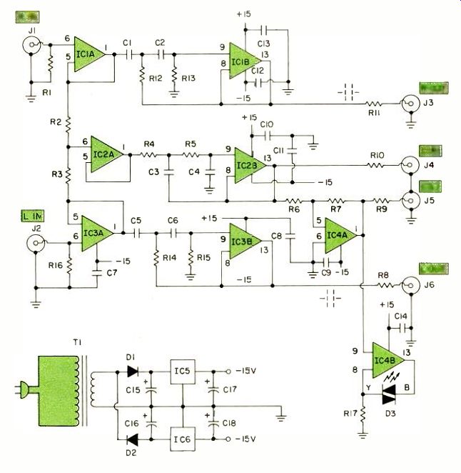
Fig. 2-Schematic diagram.
Operating Instructions
To be worth the effort, the center speaker should be a very high quality reproducer over the sub-bass, low-
bass, and mid-bass ranges. This generally means a large woofer (or equivalent) housed in a large enclosure that is well coupled to the listening room.
[Editor's Note: Plans for such a speaker are elsewhere in this issue.] To add a small, ineffective center-channel re producer, even to a mediocre stereo system, is a waste of time and money.
Like so many things in this world, the center-woofer technique must be properly implemented to be effective.
The choice of crossover frequency requires a little thought and a little measurement for best results. If set too high, the listener can discern the direction of the sound coming from the center channel. If set too low, the R and L speakers might have to handle frequencies at which their performance is poor. The 100-Hz crossover frequency specified in the preceding text is merely an average suggested value. The ideal crossover frequency depends on several factors: The capabilities of the stereo speakers and the center woofer, the roll-off rate of the crossover filters, etc. You can and should use the lowest possible frequency consistent with the performance of the center woofer and the R and L speakers. For example, if your stereo speakers sound poor even at mid-bass frequencies, you should choose a relatively high crossover frequency, i.e. 120 Hz. However, if the stereo speakers sound reasonably well in the mid-bass, and only the low bass is deficient, a lower crossover frequency (i.e. 80 Hz) is better. A good choice in most situations would be 100 Hz, which leaves a reasonable margin for error.
After selecting the crossover frequency and soldering in the appropriate value resistors (per Table III), assemble the sound system as follows:
1. Connect the R preamp output jack to the R crossover in jack (J1).
Connect the L preamp output jack to the L crossover in jack (J2).
2. Connect the crossover's R output jack (J3) to the R input jack of the R/L stereo power amplifier. Connect the crossover's L output jack (J6) to the input jack of the R/L stereo power amp.
3. If you are using a monophonic amp to power the center woofer, connect the crossover C(R) jack (J4) to the amplifier's input jack. If you are using a stereo power amplifier for the woofer, connect J4 to that amplifier's R input jack, and the C(L) output (J6) to the amplifier's L input jack.
4. If you're using a monophonic woofer amp, connect the subwoofer's " + " terminal to the amplifier's " + " connector, and the subwoofer's "-“ terminal to the amplifier's "-," "Common," or "Ground:' terminal. If you are using a stereo amplifier for the woofer, connect the subwoofer's " + " terminal to the amplifier's right " + " output terminal and the speaker's "- " terminal to the amplifier's left "+ " terminal. (The amplifier's "Common" terminals are not used.)
5. Make the usual connections between the R and L speakers and the stereo amplifier driving them.
6. Plug the power cord of the cross over device into a switched outlet on the preamp or receiver.
As previously mentioned, the center speaker can be located nearly any where in the listening room, preferably in the general vicinity of the R/L speakers. If the center speaker is set too far away, you might notice directionality and/or phase delay between the fundamental bass tone reproduced by the center speaker and the harmonics of those bass tones reproduced by the R and L speakers. The siting of the R and L speakers should be as before, but they should be elevated off the floor a few feet to improve the high-frequency dispersion.
When all speakers have been placed, and everything connected, operate the system and balance the volume between the center channel and R and L channels by adjusting the level control on the center-channel power amplifier.
-Good listening!
=========
Table II--Parts List
IC1 through IC4-RC4739 or XR4739 dual op-amps.
IC5-78L15, 7815, or LM340T-15 positive regulator.
IC6-79L15, 7915, or LM320T-15 negative regulator.
D1, D2-100-PIV silicon rectifier diodes.
D3-Bipolar red/green LED (IDI 5100H1/5 or XC/MV-5491).
C1 through C6-0.22-pf,-± 10% metallized polyester capacitors (Digi Key E1224).
C7 through C14-0.05-µF, 25-V ceramic disc capacitors (Digi-Key P4307).
C15, C16-220-g, 50-V electrolytic capacitors (Digi-Key P6655).
C17, C18-2.2-µF, 25-V tantalum electrolytic capacitors (Digi-Key P2045).
R1, R16-100-kilohm, 1/4-watt carbon film resistors.
R2, R3, R6, R7-4.7-kilohm, ±5%, 1/4-watt carbon-film resistors.
R4, R5, R12 through R15-1/4-watt, carbon- or metal-film resistors (see Table III for values).
R8 through R11-100-ohm, 1/4-watt carbon-film resistors.
R17-1-kilohm, 1/4-watt carbon-film resistor.
J1 through J6-RCA-type phono jacks (Keystone 576).
T1-16-V, 0.25-A power transformer (Digi-Key T102).
Power cord and aluminum case.
=========
=========
Table 2
==========
(source: Audio magazine, Aug. 1983)
Also see:
Crossovers for Subwoofer Biamping (Aug. 1982)
Thunder in the Listening Room--Subwoofer Shootout (Nov. 1992)
Muffling the Neighbors: Ten Tips to Reduce Noise (Nov. 1990)
New Lows on Home-Built Subwoofers (Aug. 1983)
= = = =