by William A. Manly [ "Director, Product Development Cobaloy Co., Arlington, Texas ]
“WHICH TAPE DO I BUY?” is an oft-heard question which has never been fully answered. This is attested to by the number of pamphlets, booklets, and articles aimed at an answer. The reef which most of the unwary ground upon is that the selection of a tape rightly starts with the machine! Many people asking this question have made the wrong first choice, and so they will never be completely satisfied with the second. An important point to remember is that no one else can make your choice for you if you are a discriminating user.
Before we get to the choice-making process, a little painless (we hope!) education is needed to define some terms, and to describe what we will call the "Audio Box" approach to understanding tape performance specifications.
Audio from Tape--A Noisy Signal
The first term is "noise." The dictionary defines this as "any disagreeable sound." This is true, but we want to get a little more specific than that, since noise is the floor of our box. We will separate noise into two components, called "frequency" and "amplitude." The noise in any system can be represented by a single line on a graph where vertical directions (in mathematical terms the "ordinate") represent the amplitude, and horizontal directions (the "abscissa") the frequency. This type of graph is called a "Bode Plot" for the man who invented it.
Units on the abscissa are in Hertz, or cycles per second, and on the ordinate, usually in decibels (abbreviated "dB"). The Hertz (abbreviated Hz) is easy to understand as this represents the pitch of any audible note. The dB is a rather slippery character, as it represents the logarithm of a ratio, and is, therefore, a relative quantity-but relative to what? There's the kicker. The answer is that it is relative (or "referenced") to anything you want it to be relative to, which is what makes it such a stinker.
We'll make it a bit easier by generally referring other levels to the "Standard Output Level" defined by several organizations, which defines this level as "Zero dB." Level set and frequency response standard tapes are available with this level recorded upon them.
Noise is generated by the tape, by the electronics of the tape machine, and in the heads. If the machine is well designed, tape noise will always have a greater amplitude than head and electronics noise. For all but first quality machines the reverse is true, making low-noise tapes a waste of money, so here is the first maxim: Be certain that your machine deserves low noise tape before you buy it. Look at Fig. 1. This is a picture of noise, plotted amplitude vs. time rather than frequency.
Figure 2 shows two sine (single frequency) waves of different frequencies. Now look back at Fig. 1. The noise is seen to be the sum of a large number of sine waves of differing frequency. These can be separated from the noise one at a time and their amplitudes plotted against their frequency. For a typical tape-limited audio system, the result is like Fig. 3. The frequencies are plotted logarithmically, meaning that the distance from 20 Hz to 200 Hz is the same as the distance between 2000 Hz and 20,000 Hz. This line is the lower limit to sounds we can hear, since once the signal amplitude drops to that of the noise, the signal tends to get masked by the noise.
Thus we have established the floor of our "Audio Box."
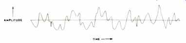
Fig. 1-A noise waveform, frequency range about an octave.
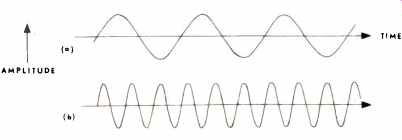
Fig. 2-Two sine waves of different frequencies.
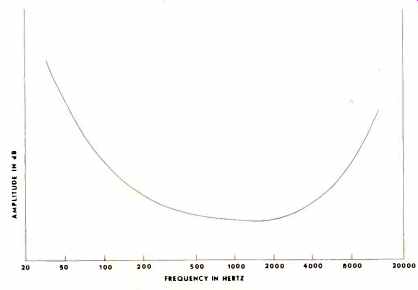
Fig. 3-Bode plot of noise amplitudes vs. frequency for a typical "tape
limited" audio tape system.
Particles and Paint
Let us digress a bit to find out how the tape noise comes about, so that you can understand just what a "Low Noise" tape is. Almost all tapes are composed of a very high quality paint (similar to a lacquer), pigmented (colored) with tiny acicular (needlelike) particles of magnetic material, and coated on a base material of plastic film. The most common types of plastic for. the base are cellulose acetate (or just acetate) and polyester terephthalate (or polyester for short). At present, most tapes are made with polyester base. The needle like particles have a length ranging from about 8 micro inches (200 nanometers) to about 50 microinches (1' micrometers-pronounced micro-meters). These particles are so small that they are single-domain, i.e., always permanently magnetized with the north-seeking pole at one end and the south-seeking pole at the other. Application of an external magnetic field can cause the poles to swap ends, but can never demagnetize them. These particles are oriented in the tape, meaning that they are arranged so that they point in the direction of tape movement across the head. When the tape is demagnetized, half of the particles have their N-pole in one direction, and half in the other. When all of the particles have their N-poles pointing in the same direction, this is called saturation, and is the strongest signal that is possible on this tape. Other signals, of varying strength, are somewhere in between these two extremes.
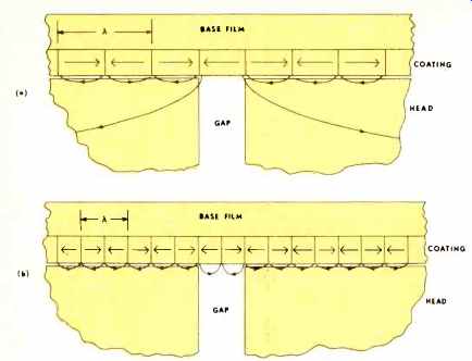
Fig. 4-(A) Simplified picture of a recorded signal passing a playback head.
Wavelength is twice the playback gap length. (B), Same, but with wavelength
equal to the playback gap length.
The Picture-Sound Analog
At any one time, the magnetic field going through the playback head comes only from those particles near the head gap.
In a standard 1/4-inch tape, using a full-track head, the number of particles involved is about 10 million. In a 4-track (stereo) cassette, the number is about 1/2 million. This change by a factor of 20 is the primary reason that a good signal-to-noise ratio is more difficult to get with cassettes. In the same way that a newspaper picture is built up with individual dots, or a television picture with individual lines, the audio signal from a tape is built up with the individual fields from each of these particles. Even with the tape completely demagnetized, there is some field fluctuation which goes into the playback head, and we call this tape noise. If the particles are smaller, we can increase these numbers given above, and we call this a "Low Noise" tape. If we cut the track width, as in going from full-track 1/4 in. to quarter-track 1/4 in., we cut the number of particles and thus decrease the signal-to-noise ratio. If the speed of the tape decreases, the number of particles "seen" per second decreases, and this decreases the signal-to-noise ratio. So-low speeds, narrow tracks, and large particles give a poorer signal-to-noise situation.
The sides of the "Audio Box" are shown in Fig. 3. They are simply the lower and upper frequency limits to the sounds we can hear. Their exact location depends on the age and sex of the listener and a number of other individual characteristics, but the outside limits are generally given as 20 Hz and 20,000 Hz.
The Top of the Box
The top of our "Audio Box" is defined by wavelength sensitive magnetic effects in both the recording and playback processes. A simplified picture of the recorded signal can be imagined as a series of bar magnets passing by the playback head gap (see Fig. 4-a). The wavelength of the recorded signal, denoted by the Greek letter Lambda (A), is comprised of two of the bar magnets end-to-end. The North-seeking poles are at the arrow heads. The magnetic flux coming out of each of the magnets is shorted through the head surface and returned to the magnets, except for one magnet over the gap, which is sending its flux through the head, and is thus being played back.
Now note Fig. 4-b. If the wavelength is no longer than the playback head gap length, no signal is sent through the head, and the signal, though recorded, is not played back. This sets a short wavelength limit on the recorded signal, which amounts to an upper frequency at a given tape speed. Playback head gap lengths are from 100 millionths of an inch (2.5 micrometers) long on higher speed machines down to about 40 millionths of an inch (1 micrometer) long on cassette machines.
Now look at the recording process, where we create those little bar magnets in the tape coating. The first thing to remember is that except for machines which use a combination record/playback head, the record gap lengths are much longer 500 millionths of an inch (12.5 micrometers) to 1 thousandth of an inch (25 micrometers). The audio signal is recorded by adding it to a large supersonic signal called bias and sending both to the record head. The bias acts in an analogous way to the power steering on your automobile. Bias does all the heavy work in magnetizing the coating, while the audio signal does the steering to control the amount and direction of magnetization. Like power steering, bias must be in proper adjustment, and we will see why it must be adjusted to match the tape in use.
In order to magnetize a piece of ferromagnetic material (like a tape coating), one must expose it to a field greater than a threshold field called the coercivity. Coercivity is sometimes sloppily called coercive force. The bias, which is about 10 times larger than the maximum signal, is used to raise the peak field produced by the head to the point where the smaller signal will record on the tape. The bias is necessary, since in its absence only the very largest signals would be recorded.
Returning to Fig. 4, the bar magnets are pictured as being rather elongated, which is the best shape for bar magnets. All bar magnets try to demagnetize themselves, and this effect gets worse the shorter and fatter the magnet. Here is where we lose a lot of short wavelength (high frequency) signal. As we shall see, making elongated, slim bar magnets is more difficult the shorter the wavelength, and it finally becomes impossible.
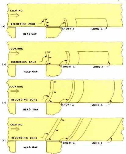
Fig. 5-(A) Tape passing the record head, with recording in progress. Bias
very small. Note the shape of the recorded signals as a function of wavelength.
(B) Same, but with a moderate under-bias condition. (C) Same, but with bias
at maximum sensitivity or lower distortion setting (there is very little
difference between these two with this ratio of coating thickness-to-record
gap length). (D) Same, but with tape in over-bias condition.
Now look at Fig. 5. All four parts show a record head in contact with a tape moving in the direction of the large arrow.
The cucumber shape at the trailing edge of the gap is the zone where the bias field peaks go from values higher than the coercivity to values lower than the coercivity. This shape is called the "recording zone" and it changes drastically with the bias amplitude, as Figs. 5-a through 5-d show. The amount of bias is nearly always (on audio machines) adjusted for either maximum sensitivity (sensitivity is playback level divided by record level) or lowest distortion, or some combination of the two. When the coating thickness is about half the record gap length, both these conditions occur nearly simultaneously, as in Fig. 5-c. This is sometimes called "optimum bias," but this is a poor term. The best short wavelength bar magnets are formed under conditions as in Fig. 5-a, where the bias is small or non-existent. The maximum output at medium wavelengths comes in condition Fig. 5-c when all the particles are being magnetized in the same direction.
Now, this part is a little involved, so pay close attention.
Since the bias is used to get over the coercivity threshold, the shape of the recording zone depends not only on the amount of bias, but upon the coercivity of the tape. High coercivity tapes are normally called "High Energy," but this term is not necessarily accurate when used this way. If the bias is adjusted per Fig. 5-c with a normal tape, and a high coercivity tape is placed on the machine without re-adjustment, the recording zone will look like Fig. 5-b or 5-a. The result is higher distortion, lower sensitivity, and an excessive output at short wavelengths (high frequencies). Thus, high energy tapes can improve the frequency response, but a price is paid. By readjusting the bias (sometimes done with a front-panel switch), the recording zone goes back to Fig. 5-c, giving a smaller high frequency gain (or sometimes none at all), but reducing the distortion and increasing the sensitivity. Some high-energy tapes have the best of both situations by using a high-coercivity layer next to the head and a standard coating next to the base film. Such a tape is compatible with standard tapes, but has an increased short wavelength response because the external layer next to the head is biased similarly to Fig. 5-a, while the thicker internal layer is biased similarly to Fig. 5-c.
This is at a single bias setting, and is a consequence only of the difference in coercivity between the two layers.
A few more items about the playback process, and we are ready to put all this together to form the top of our box. Figure 6 shows a similar situation to Fig. 4, but the tape and the head are not in intimate contact. The loss of signal is very pronounced in this case. A separation of 1 wavelength causes a loss of over 50 dB. This is about equal to the total dynamic range of your recording system! In the case of cassettes, where 15 kHz is equal to a wavelength of 50 millionths of an inch, a tiny dust particle on the tape can momentarily lose the whole high end. 50 millionths of an inch is about equal to two wavelengths of visible light. It is a distance so tiny as to be visible in the best of optical microscopes only with great difficulty. What this means as far as the tape is concerned, is that the surface of a slow-speed tape should be very smooth, even shiny. If surface roughness is visible, it will not have a good "high end." Also, a tape which sheds oxide that collects on the head will have large intermittent losses of the high frequency signals.
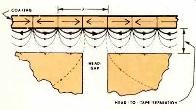
Fig. 6-Tape passing the playback head, illustrating extreme losses due
to head-to-tape separation.
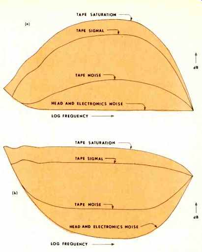
Fig. 7-(A) The complete "Audio Box" in an unequalized condition.
(B) Same, but equalized.
Playback heads have an inherent loss of signal at the low frequency end because they are sensitive to the rate-of-change of the signal (which is less the lower the frequency). At extremely long wavelengths, there is an additional loss due to the fact that only a small fraction of the wavelength is in contact with the head at any one time, and much of the flux escapes to the air. There are also some interference effects at long wavelengths which cause a wavy frequency response (these waves are called "head bumps"). You can see by the last two paragraphs that the output is eventually going to fall off to zero at both the long wavelength (low frequency) end and the short wavelength (high frequency) end. The noise output falls off as well, but all outputs eventually get so low that the electronics and head noise predominate. The frequency response can be corrected by proper electronic equalization, but the things we have talked about control the dB range between noise and maximum output at any frequency.
At midrange, the maximum output is controlled by the saturation of the material, explained previously. The long and short wavelength phenomena discussed above are further limitations, causing severe roll-off in the frequency response at both ends of the spectrum. These roll-offs are then corrected by electronic equalization, but such equalization brings up the noise as well, and this finally causes the signal-to-noise ratio to go to zero dB at some high and low frequencies. Figure 7 shows the completed audio box; 7-a is the situation before equalization and 7-b after equalization. Note that the signal-to-noise ratios are unchanged by equalization. The equalization only serves to flatten the frequency response.
Note that the dynamic range (distance from noise to saturation) is severely limited at the high frequency end and less severely at the low frequency end. This high frequency limitation gets worse with slower speeds. It deteriorates over the whole spectrum when the track is narrower. A thinner tape coating will sacrifice some of the low and middle frequency dynamic range to get an increase at the high end. Note that in all these, the tape is not generally used all the way to saturation in the low and middle frequency range because of a large increase in distortion. There' is usually little distortion for a saturation level high frequency signal, but its presence may cause distortion in any lower frequency signals present.
Happiness Is a Box That Fits! Now that you have your box with its four adjustable sides, note there is only one principle for its use: The box should be large enough to contain all the audio that you want to record.
Except for the more restricted uses, this is an ideal that is never quite reached, but the closer you get, the better the sound will be. A corollary to this principle is that buying more box than you need is not only a gross waste of money, but can actually give poorer results.
Some of the uses and box sizes are listed in Table I. Note that the low and high ranges, when multiplied, give a number close to 400,000. This is required for a balanced sound. The dynamic range required can be achieved either by adjusting the bottom or the top of the Audio Box, or both. Now note that the sizes of the Audio Boxes in Table I fall neatly into three categories: Restricted (first two), Medium (next three), and High Fidelity (last two). Now these are all rectangular boxes, so that odd-shaped thing in Fig. 7»-b is going to have to be larger than these in order not to lop the corners off when the boxes in Table I are fitted in. This is where the advertisers can fool you, if they rate their systems so highly that all the corners are gone from the boxes.
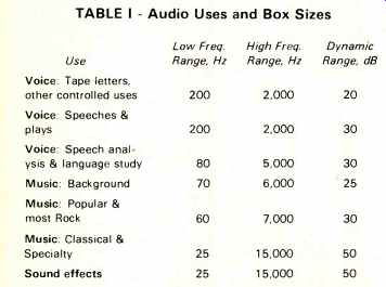
TABLE I Audio Uses and Box Sizes
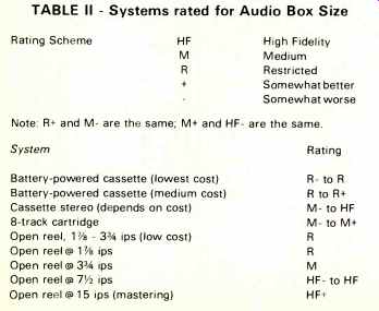
TABLE II Systems rated for Audio Box Size
Table II shows the approximate rating of most of the system types in use. Price in each category controls the exact placement. If the machine is a portable, subtract half a rating unit to a whole rating unit (this does not apply to the first two which are all portable).
Tape Selection
It is possible, with proper tape selection, to raise and lower the ratings in Table II by about half a unit. Some selections may only adjust the frequency range, while others may adjust mainly the dynamic range, but some will do both.
There are only so many things which can be done to adjust a tape for different characteristics. We will start off with a "standard" 1/-in. tape that has these characteristics: Base film thickness-1 mil (25 micrometers)
Magnetic Coating thickness-0.4 mil (10 micrometers)
Magnetic material-gamma ferric oxide Particle length-32 microinches (0.8 micrometers)
Saturation remanence--1000 gauss
Coercive Force--280 oersteds
Of these characteristics, we have not mentioned the saturation remanence. This is a measure of the magnetic strength of the particles, their concentration, and how closely they approach being perfectly oriented. This measurement is proportional to the medium wavelength saturation output divided by the coating thickness. The coating and base thicknesses for a standard cassette tape are about half those given above.
There is one last tape problem we have not yet discussed.
When the tape containing a signal is wound up in a reel or cassette, some of the signal will gradually record onto the adjacent layers. This is called "layer-to-layer signal transfer," or "print-through." It is made worse by time, high temperatures, high winding tension, thinner base films, and high head-to-tape speeds. Only the smallest of the particles are involved, so the "low-noise" (small particle) materials tend to have poorer print-through characteristics, but not necessarily.
Obtaining a "low-noise, low-print" material is one of the triumphs of the magnetic material maker's art.
Base Film Material
The advantages of acetate are low cost and the fact that it breaks cleanly and does not stretch. 1 mil thickness is the thinnest acetate available. It is getting difficult to buy tapes on acetate as most tapes are now coated on polyester, either tensilized or non-tensilized. The tensilized polyester stretches less than the non-tensilized. Other plastic films such as PVC are intermediate between acetate and polyester. The very thinnest bases (1/2 mil and less) must be on tensilized polyester.
Base Film Thickness
The thicker bases are stronger and easier to handle and have less print-through, but less can be wound on a reel or cassette. As a rough rule of thumb, dividing the tape speed by two will allow a base film of half the thickness to be used, while maintaining about the same audible print-through. Remember that the longer lengths of tape are normally achieved with a thinner base material.
Magnetic Coating Thickness
This has a complex effect on all the tape properties, and there is an interaction with the magnetic properties of the coating and the gap length of the record head. Generally speaking though, with everything else the same, a thinner coating buys an extended short wavelength (high frequency) response and dynamic range at the expense of higher distortion and reduced medium and long wavelength dynamic range. Cassette tapes have thinner coatings, and so may "long-play" types of tapes.
Magnetic Material
As opposed to plain gamma ferric oxide, from which most tapes are made, other materials may give higher coercive force, or high specific output (a stronger magnet from a given size particle), or a smaller particle, or some combination of the three. Higher coercivity will give more short wavelength dynamic range, at the expense of higher bias requirements. Higher specific output gives an increased output of both noise and signal, independent of wavelength, which results in an increase in the dynamic range at both extremes of wavelength. A smaller particle gives a lower noise characteristic, which increases the midband dynamic range. Of the three main alternatives to plain gamma ferric oxide, cobalt doping (generally used in "high energy" tapes) gives a higher coercivity only; chromium dioxide gives a controllably higher coercivity and a higher specific output; and metal particles give all three in a controllable fashion. There are also small particle gamma ferric oxides with a higher coercivity. Lastly, an effect similar to a higher specific output can be obtained by putting "more pigment in the paint," called a "higher loading" by the paint chemists.
This has the disadvantage of lowering the coercivity of the coating. The "high output" tapes normally use this method, plus a thicker coating.
Sorting Out the Sales Blurbs
Trying to decide which of these approaches (or combination of approaches) has been used in a particular case may be confusing even to the experts. Many times an analysis requires the availability of a complete test laboratory. Nevertheless, we will try to list some commonly used marketing names with the various improvements used.
Base Film material
Usually named, but may use trade names.
Base film thickness
The thinner tapes use such names as "long play" or "LP." The more tape on a reel or cassette, the thinner the base (usually). Magnetic coating thickness A "long play" tape may have a thinner coating, as do "slow speed" and cassette tapes.
Magnetic material
"Chromium dioxide" is self-explanatory. DuPont's trade name is "Crolyn," and several other names are used. "High energy" or "HE" usually means cobalt doped iron oxide. It's a bit too early to know all the names which will be used for metal particle tapes-if they become available.
Other terms "Super Dynamic," "Extra Dynamic," "Ultra Dynamic," " Extended Range," "Ultra-High Fidelity (UHF)" and the like, usually signify a compromise of a smaller, high coercivity particle; a somewhat thinner coating; and a very smooth surface. The noise is usually lower and the short wavelength response extended. With proper choice of material, higher distortion can be avoided. "Professional" usually has about the same properties as "General Purpose," but the former are closer to being alike from reel to reel. These are standard tapes with no enhanced qualities. "Low Noise" is self-descriptive, but such tapes sometimes have extended frequency response and higher distortion. "High Output" is also self-descriptive, but usually has degraded frequency response and low distortion. There are a few "Low Noise, High Output" tapes, which are nearly standard but with increased dynamic range (higher top and lower bottom on the box). "Low Print" tapes have a special magnetic material with very few extra-fine particles. It is standard except for the low print-through characteristics.
Machine Format Selection
Playback Only:
For this application, you have little or no choice of the tape. Generally speaking, you should check to see what is available in each of the formats: open reel, cartridge, or cassette. Open reel still offers the best fidelity, then cassette, then cartridge (cartridge has more capability, but it is usually not exploited). Cassette units are more portable, and cartridge units are best for one-hand operation, needed in automobiles.
Recording:
Use If you will be doing any editing, then open reel is for you. The higher the speed, the easier the editing.
Cassettes are very difficult to edit, and cartridges all but impossible. High fidelity also indicates open reels and high speeds.
It takes a very good recordist to get anything but an amateurish sounding recording on a cassette, and very few cartridge machines record at all. Sound-on-sound and other musical effects also usually call for open-reel.
For recording in the field, the portability needs should be carefully balanced against the need for fidelity. Cassette units are very portable, and nothing else should be considered for voice recording. Some cassette units have automatic volume control, and are especially useful for recording conferences.
Musical events are best recorded on reel-to-reel units, unless the portability of a cassette unit is an overwhelming consideration.
Fitting the Tape to the Machine
Working basically from Table II, we can now use our knowledge of tapes to enhance or degrade the quality ratings given.
Why should we want to degrade? One word-cost. If you are merely sending taped letters, it's ridiculous to use a high quality tape. An inexpensive one will do as well. There is one trouble with "white box" or off-brand tapes though-you never know what you're getting. If you find one that is shedding badly or otherwise coming apart, hanging up in the machine, squealing, etc., it's best to discard it.
To employ the machine at its rated use according to Table II, utilize one of the "General Purpose" or "Super Dynamic" tapes. More consistent results will be had from a "Professional" or "Mastering" type tape. "Low Noise," "Low Noise, High Output," "Extended Range," "Extra Dynamic" or "Slow Speed" tapes can be used on top line machines with an "M" or "HF" rating to extend their rating about half a step. It's a waste of money to use these tapes on the lower cost machines.
If you need maximum playing time, go to a thinner base or "Long Play" tape. If the recording must be stored a length of times, a "Low Print" tape should be used. If you cut the speed to get longer playing time, use a "High Energy," "Ultra Dynamic," "Ultra High Fidelity," "Slow Speed," "Chromium Dioxide," or other " Extended Range" tape to try to maintain fidelity to some extent. Make sure that the tape is compatible with the machine. Some can't handle chromium dioxide.
"High Output" tapes are useful on recorders which have run out of gain control or are marginal for recorded volume. "Low Noise, High Output" tapes should be used only on the better machines in this category.
Experimentation Is Necessary
Nothing beats making a trial run of a different type of tape.
If you can't hear any audible difference, use the lower cost tape. Always make sure that the tape you use does not squeal or deposit its oxide in globs on the heads and guides. A very small amount of dry shed in powder form is all right, but very much of this is aggravating. Use a brand of cassettes or cartridges which run smoothly and do not hang up. Good luck on your selections and recordings! Acknowledgement: To William H. Orr, without whose encouragement this article would not have been written.
Credits: This was written when William A. Manly was Senior Physicist at Orrox Corporation. As of April 1, 1974 Mr. Manly is the Director of Product Development for The Cobaloy Company (A Division of Graham Magnetics, Inc.). It was written primarily as a booklet to be distributed by the International Tape Association, Inc., World Tape Center, Tucson International Airport, Tucson, Arizona 85734 (Executive Director, Larry Finley).
(Audio magazine, Sept. 1974; William A. Manly)
Also see:
Cassette Deck Transport Problems (Sept. 1974)
= = = =