What it is, how it's measured, and its influence on performance of modern, lightweight phono cartridges.
JAMES H. KOGEN [Shure Brothers, Inc., Evanston, Illinois, USA]
As THE ART OF STEREO disc reproduction is refined, we must pay more and more attention to the details of equipment design and use. Years ago, when tracking forces were measured in ounces, there was little need to be concerned with fractions of a gram. Today, with tracking forces in the order of one gram, a fraction of a gram can become an important factor. The same comparison can be made for a number of factors which had little effect in bygone days, but which today loom as important considerations.
One such factor is skating force. This is a force, developed in single pivot tone-arm systems, which draws the arm toward the center of the record. We will discuss later in the article how this force is developed.
The tracking force of the tone arm is normally assumed to be divided equally between the inner and outer groove walls. This is true under static conditions when there is no relative motion between the record and tip. Under playing conditions, when the record is moving, the existence of uncompensated skating force effectively increases the tracking force on the inner groove wall and decreases the tracking force on the outer groove wall.
Specifications for all phonograph cartridges include a statement of minimum tracking force. This force is chosen as being the minimum needed to keep the stylus tip in contact with the record under maximum conditions of modulation velocity and frequency. This minimum tracking force must be maintained in order to insure proper tracking (see "Trackability," Audio Magazine, November 1966).
As stated here, the existence of skating force will lower the effective tracking force on the outer groove wall. Thus, if the user were to set the tracking force at one gram and if the skating force were, say, 0.2 grams, the effective tracking force on the outer wall of the groove would be 20% less than without skating force. This would result in sub-standard trackability for the right (outer groove) channel. To realize the manufacturer's specification, therefore, one would have to supply some kind of compensation to overcome the skating force.
On the inner groove wall, the addition of skating force increases the effective tracking force. Thus, one would not expect tracking to be a problem. This additional force, however, over and above the intended tracking force, could increase record and tip wear. This, in fact, occurs, as will be shown later.
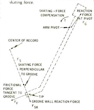
Fig. 1--Vector diagram shows frictional and skating force.
How skating force is produced
Fig. 1 shows diagrammatically how skating force is developed. Friction between the stylus tip and the record produces a force, Ft, tangent to the record groove at the stylus tip. The reaction force of the arm, Fg, must pass through the arm pivot. The two forces Fg and Fg combine as vectors, leaving an unbalanced force, F, which is by definition the skating force. The inner-groove wall opposes this force with a reaction force, Fr, thus making the inner groove force greater than the outer groove force. If the force opposing F is provided by other means, the reaction force Fr can be eliminated and the forces on the two groove walls equalized.
Skating force compensators are provided in several available tone arms. These compensators provide a torque by means of a weight or spring. This torque, T in Fig. 1, balances the torque from F,. It therefore removes the need for the inner groove wall to oppose F,. When such a system is perfectly balanced, F,r is zero.
The geometrical arrangement of the arm and record will affect the magnitude of skating force. The force is, therefore, dependent on such factors as the distance from the stylus tip to the center of the record, the length of the tone-arm (between tone-arm pivot and stylus tip) and the distance between the tone-arm pivot and the center of the record.
The latter two factors will be a constant for a given installation. The first factor, of course, will vary as the record is played.
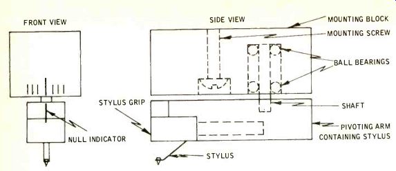
Fig. 2-Diagram of skating-force detector.
Since skating force results from the frictional force tangent to the record groove, it is important to learn more about the factors which affect this frictional force. One such factor is the coefficient of friction between the diamond tip and the vinyl record. This coefficient will be a function of the smoothness of both surfaces as well as the characteristics of the materials themselves (including additives in the vinyl). Surface contaminants on the record will also influence the value of the coefficient.
Another factor influencing this frictional force is the indentation of the tip in the record surface. The subject of record deformation or indentation has been studied intensively by Huntl, Barlow 2, 3, 4, and Walton 5, as well as others.
In our studies, the primary objective has not been to measure indentation, but to determine its effect.
Since indentation is directly related to tracking force, tip size, and possible groove velocity, these variables were chosen as factors to measure in relation to frictional and skating force.
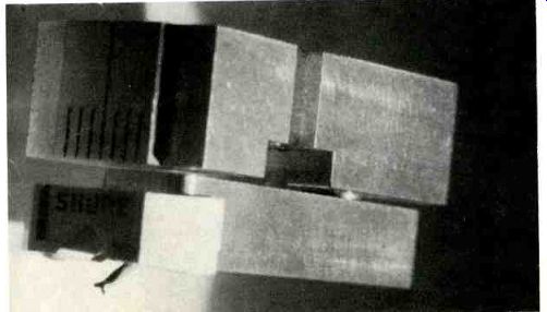
Fig. 3-Skating-force detector.
There is little data in the literature relating frictional force to modulation velocity.
--------------
1. "On Stylus Wear & Surface Noise in Phonograph Playback Systems," F. V. Hunt, Journal of the Audio Engineering Society, Vol. 3, No. 1, January 1955, Pp. 2-18.
2. "Comments on the paper, 'On Stylus Wear & Surface Noise in Phonograph Playback Systems'," D. A. Barlow, Journal of the Audio Engineering Society, Vol. 4, No. 2, July 1956, Pp. 116-119.
3. "The Limiting Tracking Weight of Gramophone Pickups for Negligible Groove Dam age," D. A. Barlow, Journal of the Audio Engineering Society, Vol. 6, No. 4, October 1958, Pp. 216-219.
4."Groove Deformation in Gramophone Records," D. A. Barlow, Wireless World, Vol 70 No. 4, April 1964, Pp. 160. 5 Gramophone Record Deformation," J. Walton, Wireless World, July 1961, Pp. 353-357.
6. "A Stereo Groove Problem," G. Alexandrovitch, Journal of the Audio Engineering Society, Vol. 9, No. 1, January 1961, Pp. 166-168.
----------
Alexandrovitch has reported an increase in skating force with modulation velocity. Additional work on this variable seems to be in order, particularly to determine whether the change in force with modulation is a first- or second-order effect. Although one would not expect to counterbalance the high frequency variations of skating force under playing conditions, it might be possible to balance out at some average modulation level rather than at a zero level, if this seems to be warranted.
Measuring skating force In measuring skating force, our approach is to simulate the actual dynamic conditions encountered when a record is being played. This means, essentially, that one should use the stylus of an actual phonograph cartridge. This can be accomplished by using a device as depicted in Fig. 2. A photograph of such a device used in Shure Laboratories is shown in Fig. 3. The device is a null-balance indicator which is mounted in the tone arm in the same fashion as a standard cartridge.
When a counteracting force is applied to the arm in a horizontal direction, of sufficient magnitude to balance the skating force, the detector will move to the null position.
This system has a reproducibility of about 0.007 grams at the needle tip when used with the Shure SME 3009 tonearm.
Fig. 4 shows the device mounted in a Shure SME arm from which the anti -skating bias adjustment has been removed. The indicator of the measuring device points off-center, indicating an unbalanced skating force. In Fig. 5 the anti-skating bias adjustment is installed and set to exactly counter-balance the skating force. In this case, the indicator points to the null position, showing that the skating force has been counterbalanced.
The measurement is made by determining the skating force compensation needed to achieve a balance.
Skating force is then calculated from the summation of moments about the tone arm pivot.
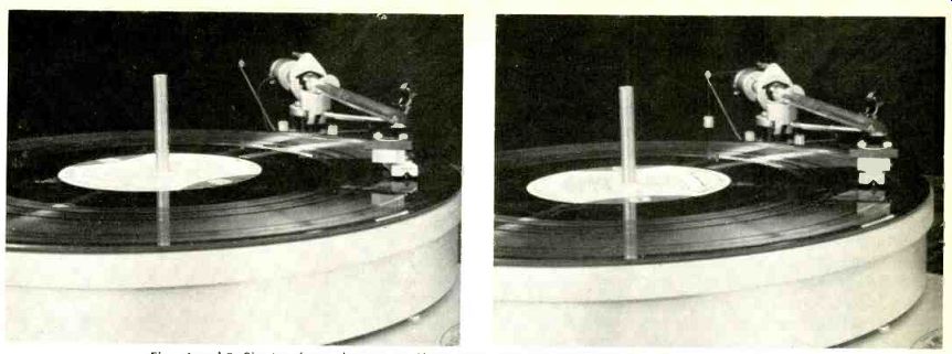
------- Figs. 4 and 5--Skating-force detector in Shure SME tone arm
illustrates how it operates without bias compensation or anti-skating
force (left) and with satisfactory bias compensation (right).
Measurement Results
One of the complications in this study has been the large number of variables. We find, for example, that skating force varies somewhat as a function of record radius. This means than an entire set of measurements must be made at several radii.
Skating force also varies with modulation velocity. This means that a complete set of measurements must be made for a series of modulation velocities and that we must measure for the entire series of modulation velocities at each of several record radii.
A number of other variables such as tip radius, record material, groove velocity, and tracking force must be measured with all of the other variables in some kind of logical combination. And, finally, if this weren't enough, sufficient measurements must be made to get some kind of a significant statistical sample, which means that each measurement must be repeated with a quantity of tips and records.
From a practical standpoint, and to provide accurate compensation, it is important to know how skating force varies with tracking force. As a consequence, we have attempted to boil down all of the data into a logical combination related to the tracking force. The ensuing paragraphs will describe how several variables influence this relationship.
For a starting point, the skating force in a blank groove vinyl record at 3.75 inch radius and 33 1/3 rpm is defined as the base skating force.
Using this as a base, we can then compare the skating force which would be developed when modulation is added, when the tip is changed, when groove radius and groove velocity vary, and when the record material is changed.
Base Condition. Fig. 6 shows the relationship between skating force and tracking force for the base condition. These measurements were repeated on a large number of vinyl records with unmodulated grooves.
Up to about 1 1/2 grams of tracking force, repeatability was quite good.
Above 1 1/2 grams there was a significant spread in the measurements, as shown in the illustration. This spread in measurements was noted throughout our study. Factors which may contribute to this are:
1. The reproducibility of the measuring apparatus. This we feel is a relatively, small contributor, being a constant value of about 0.007 grams of skating force as compared to a maximum variation in the data of about 0.1 gram.
2. Variations among several pressings of the same record. This was particularly noticeable in all of our measurements and will be discussed in more detail under "Groove Radius."
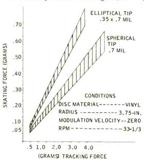
Fig. 6--Skating force vs. tracking force.
3. Possible changes in the stylus tip/record frictional characteristic at higher tracking forces. The spread in measurements has a definite tendency to increase at higher tracking forces. It is possible that at the higher forces the elastic limit of the vinyl is exceeded to a point where the forces produced by the tip begin to drastically deform and possibly tear up the surface of the groove. If this is the case, one would expect rather unstable conditions which would lead to a variation in measured frictional force.
4. Surface contamination. Our records were maintained in a clean condition through continuous and careful use of the Manual Parastat record cleaner. It is probable, however, that sufficient contamination remained on the record to cause a variation when making measurements on a series of records.
Elliptical Tip. Fig. 6 also shows relationship of skating force to tracking force for a 0.35 x 0.7 mil elliptical tip. Measurements on this tip also show a spread when performed on several pressings of the test record. The slope of the curve for the elliptical tip is about 0.2 grams of skating force per gram of tracking force. This compares to a somewhat lower slope for the 0.7 mil spherical tip of 0.15 to 0.18 grams of skating force per gram of tracking force.
Modulation Velocity. Figs. 7 and 8 show the effect of modulation velocity for spherical and elliptical tips. Modulation was 80%, 400 Hz; 20%, 4000 Hz. In reviewing these curves one should bear in mind that this covers a particular situation with regard to frequency. Therefore, generalizations should be made with great care.
Figs. 7 and 8 indicate the amount of increase one might expect for a rather extreme condition of modulation of 27.1 cm/sec. This would be about the maximum velocity one would find in a good-quality commercial record. This would indicate that for average modulation velocity in the order of 5 cm/sec, the percentage change in skating force is relatively small. Counter-balancing of the skating force in a blank groove should then provide a reasonable condition for calibration.
Record Material. As stated previously, wide variations in skating force were found among records tested. This variation was found on both vinyl pressings and acetate discs cut specially for these tests.
Additionally, the frictional force measured on the acetate discs was found to vary as a function of record aging.
In comparing record materials, a number of factors enter into the picture which might alter the measurements. In addition to the material itself, its formulation, its age, and the variables associated with the manufacturing process, one can also conceive of variations caused by the manner in which the groove was cut.
The cutting stylus shape, temperature at which the cut was made, velocity of cut, and inherent noise in the cutting system, might all contribute to variations in frictional force.
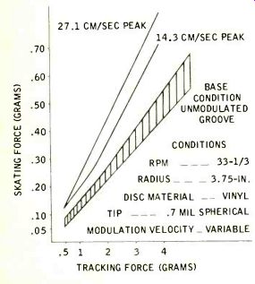
Fig. 7--Typical effect of skating force vs. tracking force, modulated groove, spherical stylus tip.
Considering all of these factors, we would hesitate to state any specific ratio of skating force for acetate versus vinyl records. In general, the skating force of discs we measured was roughly double on the acetate discs as compared to vinyl discs.
This point should be considered by recording engineers in setting skating -force compensation for tone arms which might be used in playing acetate discs.
Groove Velocity. Measurements were made of skating force versus groove velocity using 0.7 mil and elliptical tips on blank-groove vinyl records. The test was performed using a turntable in which the speed could be varied from 25 to 100 rpm.
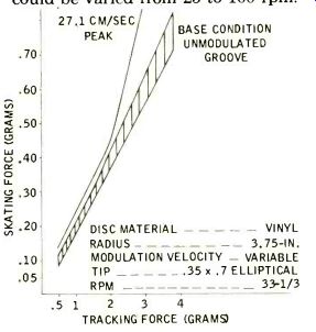
Fig. 8--Typical effect of skating force vs. tracking force, modulated groove,
and elliptical stylus tip.
This speed change of 4 to 1 is higher than the change encountered as the stylus goes from the outside to the inside of the record (roughly 2.3 to 1.). Within the accuracy of the measuring apparatus, there was not a measurable change in skating force for tracking forces between 1 and 4 grams for either tip.
During this test every effort was made to maintain a stable condition, including the use of a turntable supplied with a vacuum attachment for keeping the record flat. Nevertheless, slight eccentricities in the record grooves caused some difficulty in taking readings at higher velocities. Our conclusion is that although more precise measurements may show some change in skating force with velocity, the change is small enough to be considered insignificant in practical skating force compensation.
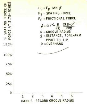
Fig. 9--Skating force vs. record-groove radius.
Groove Radius. As a result of the geometrical arrangement of a single pivot tone arm system, skating force will change as a function of groove radius.? This variation is shown in Fig. 9. This figure is based on the mathematical expression shown in the illustration. It assumes a constant frictional force between tip and record. Measurements on blank grooves followed this curve within a range of ± 5%. A question arises as to whether the frictional force between tip and record is constant as a function of radius. We know that groove velocity varies with radius. As pointed out above, however, frictional force appears to be constant with velocity.
Nevertheless, a number of our measurements indicated a change in frictional force with groove radius. A large number of tests were run in order to determine what might cause frictional force to vary with radius.
Measurements were made on both acetate and vinyl records. Tests were made on special records cut with circular rather than spiral grooves in order to eliminate the effect of tonearm movement. Tests were made on records with the spirals cut from the inside out as well as the outside in, records cut at 78 rpm as well as 33 rpm, and records where the frictional force was purposely altered by wetting the surface.
7. "Tracking Angle in Phonograph Pickups," B. B. Bauer, Electronics, March, 1945.
Part 2
JAMES H. KOGEN, Shure Brothers, Inc., Evanston, Illinois.
The author sums up the effects of skating force on the overall performance of the phonograph system.
Our conclusion, after reviewing the results of all of these measurements, is that the frictional force is essentially constant as a function of groove radius, but that it does change as a function of a number of other factors. These factors could, in turn, change with record radius although not necessarily in a consistent fashion. Such factors might include material hardness, surface roughness--possibly as a function of additives, groove shape, warpage, and dishing of the record. Whatever the cause, significant differences in measurements were noted from record to record and at various radii on the records.
In passing, we should mention that little difference was noted between measurements on circular versus spiral grooves, or between the spirals from the inside out versus the outside in. From a theoretical standpoint, the inward movement of the tone arm as the record is played, should introduce a constant frictional drag related to the viscous damping in the tone arm bearing system. The low velocity of the arm as it moves toward the center of the record, coupled with low viscous damping in the arm, should result in negligible drag in a good system.
A brief comment should also be made on measurements on wet surfaces. These measurements were made pretty much from the standpoint of curiosity, but did show some interesting results. Frictional force was reduced substantially when the surface was wet. Measurements seemed to be much more uniform under this condition.
Overhang. The installation of the arm is very critical in determining the amount of skating force one would obtain for a given tracking force. All of the above curves, Figs. 6-9, are based on an optimum overhang for the 12-in. Shure SME 3009 arm of 0.6-in.
Fig. 10 gives the variation in skating force as a function of overhang for a given tracking force. This curve shows that if the arm is installed with an improper overhang, the calibrations on the arm for skating-force compensation will be incorrect. For any separate tone arm, great care should be taken in the initial installation. Even with record changers, one must be careful in installing the cartridge to make certain that the overhang is accurate.
Effect of Dirt. It was noted throughout this study that the measurements were very seriously affected by any accumulation of dirt on the stylus tip and on the record.
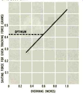
Fig. 10--Change in skating-force compensation as a function of overhang
of the SME 3009 arm.
All of the above measurements refer to a situation in which both the record and tip were kept clean. This requires washing or use of an effective record cleaning device such as the Manual Parastat. In spite of the great care which was observed, some of the variability in the results was probably caused by small accumulations of dirt on the record surface.
To eliminate this variation, future measurements might be made using records cleaned after the fashion described by Percy Wilson. 8.
8. "Record Contamination: Causes & Cure," P. Wilson, Journal of the Audio Engineering Society, April, 1965, Pp. 166-180.
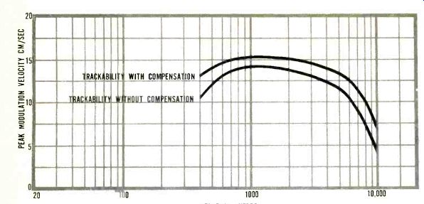
Fig. 11--Trackability with and without skating-force compensation.
Skating-Force Affects Trackability. In addition to making actual measurements of skating force, it is of considerable value from a functional standpoint to determine how skating force is related to the ability of the needle to track the record modulation. Fig. 11 is an example of trackability for a medium-quality cartridge, at minimum rated tracking force, with and without compensation. The upper curve shows the trackability (maximum modulation velocity the cartridge can track as a function of frequency) with proper skating-force compensation. The bottom curve shows a repetition of the test, but without skating-force compensation. In this test, the bias compensation improved trackability in the order of 20 to 25% in the frequency range shown.
It has been suggested that one method of overcoming the skating force is simply to increase the tracking force. In order to check this, the same test was run without skating force compensation, but with an increased tracking force to achieve the same trackability as shown in the upper curve. It was found that the tracking force had to be increased from 1 gram to at least 1 1/2 grams to provide equivalent trackability over the complete frequency spectrum.
Life Tests
Another factor under consideration is that of the effect of tip wear with and without skating force compensation. To evaluate wear, life tests without skating-force compensation were run on 14 cartridges for several hundred hours each. Such a test must be run with a reasonable number of units because of probable variations in the diamond tips and the records being used for the test.
Fig. 12 is a photograph of an unsymmetrically worn tip after the life test without skating force compensation.
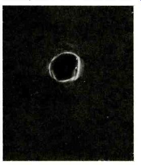
Fig. 12--Spherical tip after life test without skating-force compensation.
Results of these life tests showed that 9 of the 14 tips wore appreciably faster on the side towards the inner groove where the force would be larger because of the addition of skating force. On four of the units the wear was equal and on one unit the side towards the outer groove wore first. While this is not conclusive evidence, statistically speaking, the indication is that the skating force has an effect on tip wear.
A second test was performed with anti-skating compensation. Of six units, all showed equal wear on both sides of the tip.
These life tests indicate that from the standpoint of wear, compensation by means of a horizontal bias (anti-skating) force is preferable to increasing the tracking force (VTF). The horizontal bias compensation equalizes the tip wear and optimizes tracking conditions, whereas increased tracking force increases the wear in order to obtain equivalent trackability.
Conclusion
The objective of these studies has been to make measurements which will aid in providing a better understanding of the skating-force phenomena. Although a considerable effort has been expended in developing the data shown here, it is our feeling that a great deal more work will be needed to develop a complete understanding of the physical situation.
One variable which must be studied in greater detail is the variation among vinyl and acetate record materials. Within the realm of a given record material, there are several variables, including: additives, the molding temperature and cycle, impurities, and the age of the record.
It would be very valuable if one or more parameters of the material could be determined which might be standardized in measurements of the type described here. We have noted several anomalies in the measured data which apparently relate to the record material. This point is important because a repetition of the tests reported here, with some change in the record material, could produce somewhat different results.
In several of the referenced papers (1, 2, 3, 4, & 5) , tests were made using spherical tips on flat vinyl surfaces. If the tip is truly spherical there should be a direct relationship to similar measurements in blank grooves. One should not, however, expect such a direct relationship with elliptical tips. Ellipticals are not specified in such a way as to completely define the shape and curvature of the bottom surface. Any attempt to relate measurements of elliptical tips on blank discs to measurement in grooves can, therefore, be very misleading. For accurate adjustment we recommend that the user follow instructions given by the tone arm manufacturer.
These tests indicate that a gross compensation of skating force can be achieved by using a constant bias force directed horizontally. The residual, unbalanced forces which result from changes in modulation velocity, groove radius and groove velocity, will contribute second order effects which should not have a major influence on factors such as trackability and tip wear. The compensation must be made for a specific tip at a given tracking force and for a particular record material.
(The writer wishes to express appreciation to C. R. Anderson, B. Jakobs, and R. Young of Shure Brothers, Inc., for their work in developing the test apparatus, making measurements, and analyzing the test data.)
Also see:
Skating Force--Mountain or Molehill? (March 1967)
A Quiet Phonograph Preamplifier (Oct. 1972)
How we test a Phono Cartridge (Aug. 1972)
A New Concept in Diamond Syli (Aug. 1972)
Ultra Low-Noise Phono Preamp [theory, concept, design and DIY project]