by R. S. OAKLEY JR.
In which the author discusses the side thrust toward the center of the record which results from modern tone arm geometry, and ways of reducing its effect.
IT IS POSSIBLE to demonstrate dramatically the tendency of a modern tone arm to "skate" toward the center of a rotating record. The demonstration requires a tone arm with an "anti skating" device. With the device disabled, the needle is placed at the outer edge of a rotating blank vinyl disc. Immediately the tone arm moves toward the record center. When the anti-skating device is brought into play and the tone arm is again placed on the groove-less record, it stays in place.
Equally dramatic was a demonstration first used about five years ago to show that skating force can result in distortion which can be eliminated by an anti skating device. In this demonstration the output of a stereo cartridge was displayed on an oscilloscope while a very high-level sine-wave signal on a test record was being reproduced. With the device disabled, distortion was visible in the right-channel display. When the device was brought into play, the distortion disappeared
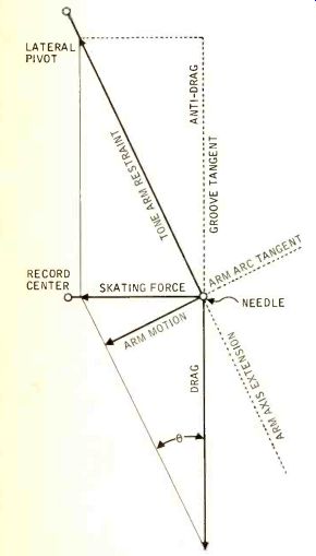
Fig. 1. A diagram of the skating-force vector.
A third demonstration, while perhaps not so dramatic, brings the problem into perspective. Here the output of a stereo cartridge is again displayed on an oscilloscope (or played through loudspeakers) while a test signal is being reproduced.
The needle force is low enough that, although left channel information is undistorted, noticeable distortion exists in the right channel. Needle force is then increased by a small fraction and right channel distortion disappears.
To understand exactly what these three demonstrations prove, the nature of skating force should be examined. The following formula applies: SF = µ N tan Φ., in which SF = skating force, µ = the coefficient of needle/groove friction, N= vertical needle force, Φ = the angle between the groove tangent and the line from the needle to the lateral tone arm pivot. Since skating force is approximately proportional to needle force, it is customary to express skating force in terms of needle force.
Definition
Skating force is defined as side thrust normal to the groove tangent. The friction of the needle in the groove produces a drag which may be represented as a vector away from the needle along the groove tangent and which must be balanced by an equal but opposite force.
Because in a properly designed offset tone arm these two forces are never opposite in direction, a side-thrust vector is formed. This vector, Fig. 1, is determined by a parallelogram in which drag and tone-arm restraint (along the line from the needle to the lateral pivot because the arm is restrained at the lateral pivot) are two sides. Side thrust does not coincide with the direction the arm can move (along its arc). Anti-skating force must be applied in this direction, however, and must be proportional to sin Φ instead of tan Φ.
The element in the skating-force formula for which the least data exists is µ, the coefficient of friction. It should be noted that any given value of µ applies only under certain conditions. The reason for this is that it varies not only with record material, needle force, needle radius, and perhaps even effective needle mass, but also with groove modulation (both amplitude and frequency) and groove radius. Determining the relative importance of these various factors to the value of µ is beyond the scope of this paper. It can be observed, however, that exact correlation between µ on either a blank record or a sine-wave test band and under actual playing conditions is strictly coincidental.
The other element in the skating force formula is θ, the angle between the groove tangent and the tonearm axis.
Most modern tone arms are between 8 and 9 in. from pivot to needle tip.
Since normal design procedure calls for minimizing distortion due to lateral tracking error over the entire record surface, overhang distance (the distance the needle sweeps past the record center) and offset angle (the angle between the cartridge axis and the line from the needle to the lateral pivot) will be determined from known formulas. Maximum theta will be at the outside record radius, but minimum it. will not be at the inside record radius. Rather, it will be at an intermediate radius-increasing from that point to the inner radius, as seen in Fig. 2. It can be seen, then, that even if the coefficient of friction were constant, skating force would neither be constant nor would it vary in a linear fashion. This complicates the design of anti-skating devices.
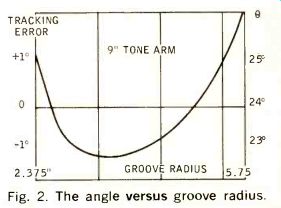
Fig. 2. The angle versus groove radius.
There are at least four means of providing an anti-skating force. One is to wind a spring around the tonearm spindle or lateral pivot axis which tends to rotate the arm toward the outside. A second is to suspend a small weight from a thread which makes a right turn before it attaches to one side of the tone arm. A third method is to tilt the vertical pivot axis so that when vertical needle force is applied (by a spring in this particular case) it is applied with a slight outward thrust. All three of these basically simple ways of supplying anti skating force suffer from inherent inability to vary the force with tan Φ. A fourth method uses a pin attached to the tone arm spindle which rotates against a lever that carries a small weight. This method is the most promising in that it might be possible to shape the bar to vary anti-skating force with tan Φ. Obviously no method can compensate for changing values of µ. All four methods offer complication of proper initial adjustment of the tone arm-their success in reducing skating force depends heavily on proper adjustment, and improper offer complication of proper initial ad adjustment may even aggravate the problem.
A digression on the role of effective arm mass-inertia-is now in order. All of the above has assumed (quite without good reason) that the tone arm is relatively undisturbed by such influences as dust in the grooves, record warp, record eccentricity, external shock, and so on.
In fact, the proper relation between the needle and the groove is constantly being upset by such influences--making simple analysis of the need for anti skating force quite impossible. Although tonearm inertia does not enter into the formula for skating force, it has been shown that a tone arm with high inertia will be more easily disturbed than one with low inertia. Simply stated, it is useless to reduce skating force unless arm inertia has been reduced to a satisfactorily low figure. Unfortunately, most modern arms have excessively high inertia.
The most serious effect of skating force is that it results in unequal loading of the two groove walls, as shown in Fig. 3. Examination of the vector diagram shows that skating force tends to reduce loading on the outside groove wall. Insufficient vertical needle force can result in intermittent loss of contact between the needle and the outside groove wall which is heard as distortion of sine-wave test signals or as noise accompanying loud music passages. But simply increasing vertical needle force (by about 15 per cent above the value which would be required if the two groove walls were equally loaded) will eliminate this distortion.
Less serious is the possibility of wear on the inner groove wall. Loading on the inner groove wall is increased by the same amount as it is decreased at the outer groove wall. This might be a disadvantage if increased loading of the groove necessarily resulted in proportionate record or needle wear. There is evidence and experience to suggest, however, that at low needle forces the record material is elastic enough that permanent deformation does not occur.
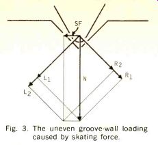
Fig. 3. The uneven groove-wall loading caused by skating
force.
Most remote of all is the possibility that inward force on the tonearm will cause the needle (which is usually attached to a lever) to be pushed outward.
This could cause lateral tracking error not accounted for in the original tone arm design, it could cause the needle lever to be forced into a region of nonlinear operation, or it could cause the stylus assembly to acquire a "set" over a long period of time. Since vertical needle force is about 6 times as great as skating force, and since vertical and lateral compliance should be identical, similar effects would occur first in the vertical angle of the needle lever.
The foregoing would appear to suggest the anti-skating devices are only partially solving a problem that is relatively insignificant to begin with, and at the same time perhaps creating very real problems of tone arm adjustment. The most elegant solution to the "skating" problem would be significant reduction of µ, the coefficient of friction, through improved record material. Until that solution is forthcoming, tone arm designers might well focus their attention on reducing inertia, providing neutral arm balance, reducing sensitivity to external vibration, and providing a means of adjusting overhang distance to achieve the lowest possible distortion from lateral tracking error. At the same time, con sumers should use care in properly setting needle force with a good test record-this being the only reliable way to do so.
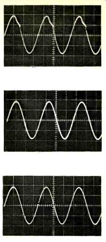
Fig. 4. In this illustration an arm with variable skating compensation has been used to show the possible right-channel distortion caused by the action of skating force. In (A) the right-channel output is shown at 1.5 grams stylus force and using no anti-skating compensation. At (B) the same tracking force and channel are shown with proper skating compensation set. (C) illustrates the same right channel without compensation but at a tracking force of 1.7 grams. The left channel never showed the effect of skating force. The signal used is the +15-dB, 300-Hz band of the CBS STR-111 test disc.
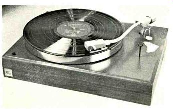
Fig. 5. An AR turntable with an anti skating device built-on consisting
of a bent paper clip held in place with tape. A small piece of thread
and a plastic gram weight complete the assembly.
APPENDIX:
For a detailed analysis of "skating force" the reader is referred to a technical paper entitled "New Approach to Tone Arm Design" presented by Mr. George Alexandrovich (Fairchild Recording Equipment Corp.) to the 1960 Convention of the A.E.S. Also extremely informative is an article entitled "The Rational Design of Phonograph Pickups" by Professor F. V. Hunt of Harvard, published in the October, 1962, Journal of the A.E.S. It should be observed that record materials have apparently improved over the last half decade. Data presented by Alexandrovich suggested a range of values for µ of from 0.4 to 0.7, Hunt suggested a range of from 0.25 to 0.5, and new experiments suggest a range of 0.2 to 0.35.
Also see:
The Skating-Force Phenomenon--Part 1 and 2 (Oct./Nov. 1967)
Tracking Capability of Phonograph Pickups
A Quiet Phonograph Preamplifier (Oct. 1972)
How we test a Phono Cartridge (Aug. 1972)
A New Concept in Diamond Syli (Aug. 1972)
Understanding Phono Cartridges (Mar. 1979)
AUDIO Equipment Profiles: H. H. Scott Speaker System S-11; Marantz Amplifier Addendum; Model 15; Wharfedale Compact Speaker W-20