MANUFACTURER'S SPECIFICATIONS
IHF Sensitivity: 1.75 µV.
S/N: 65 dB (S/N at 5µV: 50 dB).
THD (Mono): Better than 0.5%; Stereo, better than 0.9%
Capture Ratio: 1.5 dB. Selectivity: 65 dB
AM Suppression: 58 dB.
38 kHz Carrier Suppression: At least 55 dB.
Drift: Less than 0.02%.
Muting and Stereo Threshold: 4µV.
Stereo FM Separation: 40 dB @ 1 kHz (30 dB @ 50 Hz and 10 kHz).
Frequency Response: 30 Hz to 15 kHz (de-emphasized) +/- 1 dB, Mono and Stereo.
Dimensions: 13 1/2 in. W, 4 1/4 in. H, 9 in. D.
Retail Price: $149.95 kit, $249.95 wired.
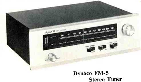
Dynaco kits have long been noted for a basic, simple look on the outside and state-of-the art performance on the inside. The FM-5 is no exception. Its business-like extruded aluminum front panel and black metal enclosure house some sophisticated r.f. engineering and layout that is ideally suited to the kit-builder of limited experience but will serve the FM enthusiast who elects to buy the unit fully wired equally well.
The front panel controls include an on/off volume control and a large tuning knob, coupled to a flywheel that easily propels the dial pointer from one end of the dial to the other with one twist of the knob. In addition, there are three 3-position rocker switches. The first of these selects MONO or STEREO operation, with a center FILTER position available for improving signal-to-noise ratios when weak stereo signals are received with some sacrifice in high frequency stereo separation. The next rocker switch is labeled AUX-FM and enables the user to select another signal source, such as tape-recorder outputs, which can be connected at the rear panel. The built-in volume control is active for this auxiliary source as well as for FM. The last rocker switch has to do with the interstation muting circuitry designed for the FM-5 and has positions for OFF, MUTE and DYNATUNE8, about which we'll have more to say later.
The large dial scale area includes a logging scale with 100 divisions in addition to the usual frequency scale. A signal strength meter is located at the left of the dial scale area and adjacent to it are two indicator lights-one of which is labeled TUNED, the other STEREO. The STEREO light, of course, becomes illuminated in the presence of a stereo broadcast.
The TUNED light is the end result of a carefully engineered sensing or logic circuit in combination with a closed–loop AFC tracking circuit which insures center-of-channel tuning and which will be described shortly, when overall circuitry is analyzed.
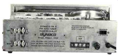
Fig. 1--Rear panel layout of the Dynaco FM-5
The rear panel of the FM-5 tuner is shown in Fig. 1. Antenna connections are provided for 300 ohm or 75 ohm transmission lines and there is a convenience a.c. outlet as well as a line fuse for circuit protection. A fixed pair of outputs labeled TAPE OUT provide approximately 2 volts of audio (under conditions of 100% FM modulation) regardless of volume control settings, and these outputs are intended for connection to a tape recorder input pair which can be controlled at the recorder itself. The AUDIO OUT jacks are for connection to your amplifier or amp-preamp components while the Aux jacks, as previously mentioned, will accommodate a stereo high level signal source. In the event that you want to make the FM-5 your "operations center" and have only a basic stereo power amplifier, Dynaco will make available a separate phono preamp (Model PPM-5) which will accommodate a magnetic phono cartridge. The outputs of this accessory could then be connected to the AUX inputs on the FM-5.
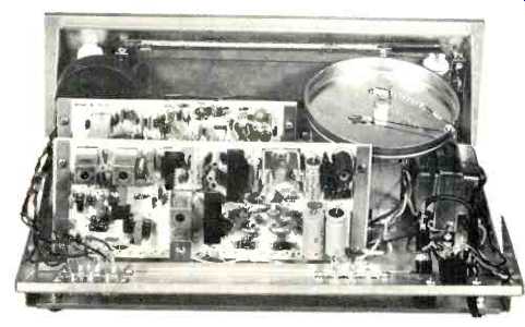
Fig. 2--Internal view showing major p.c. modules.
In Fig. 2, the assembled the top cover removed and are three major assemblies, aligned and tested. The kit the mechanical assembly of and wired FM-5 is shown with back panel swung down. There all of which come fully wired, builder is concerned only with the modules to the chassis and
their interwiring. With so much of the Dynaco FM-5 prewired and pre-aligned, the kit building phase of the project is quite minimal and well worth the effort for the difference in price between the wired and kit price of this tuner. There are 22 initial assembly steps (mechanical), 87 steps concerned with the actual wiring (mostly cutting lengths of wire and hooking them up from here to there and 12 final assembly steps. In general, we have found that Dynaco's step-by-step instructions are a bit on the brief side and could benefit from a few more illustrations. A novice kit-builder may not be able to readily identify the less familiar parts which are merely referred to by name. The kit was built by a fairly well experienced kit builder in a little over five hours, but a novice might well take a little longer.
The front-end (obscured in the photo by the large dial string drum) includes a tuned r.f. input to a Field Effect Transistor amplifier, followed by interstage double-tuning to a FET mixer. A bi-polar transistor is used for the local oscillator. The output of the first i.f. stage is tuned by a section of the four-section variable capacitor.
The basic i.f. section of the FM-5 consists of two IC amplifiers followed by a high gain limiter IC. There are four cascaded ceramic filter sections between the first and second stages and three additional filter sections between the second and third stages. Another high-gain amplifier (also an IC) drives a ratio-detector which feeds an emitter follower for audio output. There follows a 67 kHz filter for SCA rejection and an FET which feeds the muting and multiplex circuits.
An IC multiplex circuit includes a cross-coupled multiplier demodulator for additional SCA rejection. Also included are additional 19 kHz and 38 kHz rejection filter circuits and a two transistor audio amplifier which provides low output impedance and incorporates the , necessary de-emphasis circuits.
The muting circuit is controlled by a logic circuit which is fed by the detector's emitter follower audio output. Sensing the detector's d.c. level, audio is switched off when the variation from "zero center" exceeds 80 kHz. This circuit is also activated by a second signal (the output of a 150 kHz high pass filter) which consists of interstation noise. If such noise is present, audio is also switched off.
The Dynatune Circuit
This automatic circuit consists of an amplified closed-loop tracking circuit with a narrow "window." The amplified d.c. output of the detector is fed back to the front-end through a limiter. This signal controls the frequency of the local oscillator and "tracks" for zero d.c. at the detector output. Since the "looking action" is so strong that it might track a single signal over wide ranges of frequency, the circuit is so arranged that when the d.c. level reaches a predetermined value (as the tuning dial is moved), the muting logic switches off before audible noise or distortion is heard.
Electrical Measurements
Figure 3 is a graphic plot of major FM performance characteristics. IHF sensitivity was reached at a near-theoretical limit of 1.7 AT but, even more important, notice the excellence of the quieting slope. At 5 microvolts input, we observed over 55 dB of quieting (fully 5 dB better than Dynaco's published specification) and ultimate S/N for any signal level beyond 50 µV was 68 dB (as compared with 65 dB claimed by the manufacturer). Harmonic distortion in mono was a mere 0.3%, while in stereo we measured 0.55% at mid-band frequencies. As can be noticed in the graph, stereo threshold (the point at which the circuits "open up" the stereo circuitry) was 4µV and that corresponded to the muting threshold as well. This last figure is particularly significant. Less sophisticated muting circuits invariably restrict the listener to signals of greater than 7 to 10 µV-which means that if you want the benefit of interstation silence and have the muting circuits turned on, you're liable to "block out" otherwise listenable stations. In the case of the Dynaco FM-5, with a threshold of 4 µV in its muting circuits, just about any station you'd deem worth listening to (in terms of signal-to-noise ratio) defeats this muting circuit positively--with no "half-way" distortion points so common to other forms of this circuit. Stereo separation actually exceeded published specs, measuring 42 dB at mid-band and maintaining 30 dB from 50 Hz to 10 kHz.
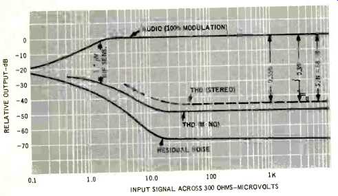
Fig. 3--FM characteristics.
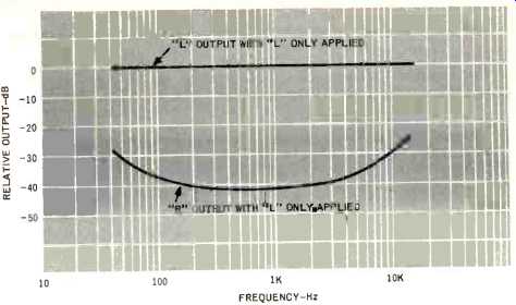
Fig. 4--Stereo FM separation characteristics.
Listening Tests
Tuning the dial of the FM-5 offers immediate proof of the superiority of Dynaco's Dynatune circuit. While the signal strength meter gives some indication of the fact that you are approaching a station, with the switch set in the Dynatune position it really is not needed. That TUNED light comes on and clear distortion-free audio is heard. There is none of the "side skirt" noise often associated with lesser "muting and tuning" circuits. No pops, no clicks just audio when ever that light lights. We found the so-called "window" to be quite narrow and critical, but that is one of the penalties you have to pay if you're going to get absolute accuracy in center-of-channel tuning. With the switch set to the MUTE position, stations came on over a somewhat broader range of movement of the dial, but of course center-of-channel precision was then left up to the user and there is some margin for the introduction of distortion as one nears the edge of the mute defeat range for each station. Dynaco suggests tuning for stations in the MUTE position and introducing the Dynatune feature only after the station has been tuned in (for final center-of-channel accuracy) and this may be the best way to work it, although the tune light must be illuminated before you can switch to this latter position for the "tracking" circuits to take over.
In our location, we were able to pick up exactly the same number of listenable stations with or without the mute circuit on--a total of 51 with our outdoor Yagi antenna facing New York City, of which 28 were broadcasting in acceptable noise-free stereo--which further attests to the desirability of Dynaco's low threshold in this new muting circuit. There was no evidence of drift at any time and, most surprisingly, calibration was excellent-never off by more than 100 kHz at any point on the dial. That's quite an accomplishment for a tuner whose front-end was aligned in Philadelphia and whose dial string and dial pointer were assembled months later at a remote kit-builder's home! In all, you're not afraid to mount some parts, cut some wires, and do a bit of easy soldering, the Dynaco FM-5 offers you expensive sounding stereo FM at a budget price.
-Leonard Feldman
(adapted from Audio magazine, Oct. 1972)
Links:
Also see:
Dynaco AF-6 AM/FM Tuner (Equip. Profile, Sept. 1974)
Dynaco PAT-5 Preamplifier (Feb. 1976)
Dynaco A-25XL Loudspeaker (Nov. 1976)
Dynaco Stereo 70 Series II Tube Amp (Nov. 1992)
= = = =