Manufacturer's Specifications:
Preamplifier
Frequency Response: Phono, RIAA ±0.25 dB, 20 Hz. to 20 kHz; high level, 4 Hz to 50 kHz, ± 1 dB.
Gain: Phono to main output, 64 dB at 1 kHz; phono to tape output, 30 dB at 1 kHz; high level to main output, 32 dB.
Gain Accuracy: Gain and balance within 1 dB of setting over 80-dB range.
S/N (Unweighted, 20 Hz to 20 kHz): Phono, 60 dB re: 1 mV rms input; high level, 84 dB re: 1 V rms output, with gain set for unity (-32 dB level setting).
Distortion at 1 V rms Output: Less than 0.03% second or third harmonic, less than 0.002% fourth and higher harmonics.
Sensitivity for 1 V rms Output: Phono, 0.63 mV; high level, 25 mV.
Input Overload: Phono, 200 mV rms at 1 kHz; high level, 10 V rms.
Input Impedance: Phono, 47 kilohms, with provision for additional loading; high level, 100 kilohms.
Output Characteristics: Impedance, 3 kilohms; maximum level, 5 V rms.
Wireless Remote Control: Operates volume, balance, and muting; transmission range, 30 feet (10 meters).
Power Requirements: 100 to 130 V or 200 to 260 V a.c., 50 to 400 Hz; 40 watts.
Dimensions: 19 in. W x 3 1/2 in. H x 13 in. D (48 cm x 8.9 cm x 33 cm) with standard rack panel; with rubber feet, 3 3/4 in. H (9.6 cm).
Weight: 11 lbs. (5 kg).
Price: $3,245; balanced line outputs, $550 additional; buffered outputs, $440 additional.
Amplifier
Power Output: 100 watts or more per channel, 30 Hz to 15 kHz, at 2% total distortion, with both channels driven.
Frequency Response: 4 Hz to 40 kHz, +0,-3 dB, at 1 watt out.
S/N: 80 dB, d.c. to 1 MHz; 100 dB, 20 Hz to 20 kHz.
Typical Harmonic Distortion Products for 1-kHz Signal: 0.4% second harmonic, 0.3% third, 0.1% fourth, and 0.3% fifth.
Sensitivity for 100 Watts Output: 0.8 V rms; balanced or unbalanced.
Input Impedance: 100 kilohms.
Ideal Output-Matching Impedance: 0.89, 3.55, 8, and 14.22 ohms for 1-, 4-, 8-, and 16-ohm taps, respectively.
Internal Small-Signal Output Impedance: 3.8 ohms for 8-ohm connection.
Power Requirements: 100 to 120 V or 200 to 240 V a.c., 50 to 440 Hz; 130 watts at idle, 550 watts max.
Dimensions: 19 in. W x 5 1/4 in. H x 17 1/4 in. D (48 cm x 13.3 cm x 44 cm) plus handles and connectors; standard rack mount.
Weight: 40 lbs. (18.1 kg).
Price: $4,290.
Company Address: 12430 McCrossin Lane, Potomac, Md. 20854, USA.

My first experience with one of David Berning's designs was with a TF-10 preamp some years ago. I fondly remember it being a very good-sounding unit. If I recall correctly, it had a switching power supply and used a hybrid FET/tube circuit for each amplification stage.
Like its predecessor, the TF-12 has a switching power supply and uses tubes as amplifying devices; however, it doesn't use FETs as in the earlier, hybrid circuitry. One of the design goals for this new preamp was to make possible reproduction from high-level sources, like CD players, without noticeable alteration of the sound--a laudable goal, for sure. Berning implemented this approach with a new dual stage, digital switching-matrix system for volume and balance control. This system yields very good interchannel tracking and a wide range of control (some 80 dB). The Berning company feels that this digital switching matrix degrades the sound much less than the standard but high quality potentiometers used as volume and balance elements in the majority of preamps. I thought it would be interesting to see to what degree the line section is audible.
What further sets the TF-12 apart from earlier Berning preamps is the inclusion of a wireless remote for volume, balance, and muting. A front-panel LED display gives the attenuation setting, in dB, for each channel, a very nice feature indeed. This permits you to note and reproduce the "just right" volume of different program sources.
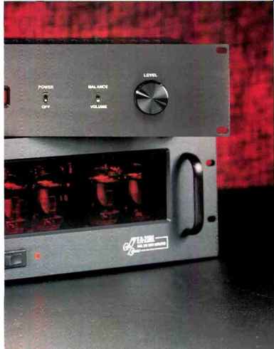
The EA-2101 power amplifier also has a number of interesting technical innovations that set it apart from other amps. To start with, the power supply is a switching design (a Berning specialty) that provides regulated voltages to all stages, including the output stage! There are not very many tube power amplifiers around with regulated high voltage to their output stages (actually, I don't recall any). The other major innovation in the EA-2101 is the manner in which the output stage is operated, a patented "triode" mode that is completely different from the conventional way of driving an output stage (more about this under "Circuit Description"). The circuitry is fully balanced from input to output, allowing feed from unbalanced or balanced lines. Finally, and dear to my heart, the front-end tubes are all 6SN7s, octal-base dual triodes that are very linear.
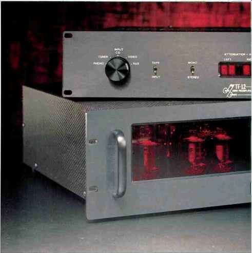
The controls on the preamp's front panel include a five position rotary source selector and four toggle switches ("Tape/Input" for tape monitoring, "Mono Stereo," "Power/ Off," and "Balance/Volume"). These are followed by a rotary "Level" control whose function is selected by the last toggle switch. Since the actual element turned by the "Level" control knob is an optical encoder, it doesn't have stops at the usual counterclockwise and clockwise limits of rotation, as regular potentiometers do. Instead, you can turn it indefinitely. When the circuit is powered up, one revolution of the control corresponds to 16 dB of attenuation change. (It feels weird to have such a control for volume-these newfangled digital things!) An attenuation display, in the middle of the panel, shows each channel's setting, in dB, to two significant digits. In the center of this display is the optical detector for the remote control. It's a very attractive front panel, in my opinion. On the rear panel are a power-cord socket/r.f. line-filter unit, Tiffany input/output phono connectors, and a gold-plated ground post.
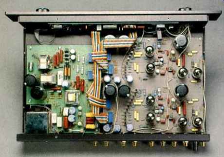
Inside the TF-12, the circuitry is broken into three major functions on as many circuit boards. Taking up more than 50% of the internal area, and located to the left as seen from the front, is the p.c. board carrying the signal circuitry and attenuator elements. This board is made of Teflon and is said to allow a more transparent sound than the usual epoxy/glass laminates. The channels are laid out separately but identically, in a dual mono arrangement. To the right of the signal board is the switching power-supply board. Numerous inductors and other parts indigenous to switching power-supply circuitry are in evidence. Mounted on standoffs, behind the inside surface of the front sub-panel, is the third circuit board, which mainly houses the digital control for the unit's switching attenuator matrix. Part of the audio signal path appears to be on this board too, as the p.c. mount "Tape/Input" monitor and "Mono/Stereo" toggle switches terminate here. Interconnection of signal circuitry is via discrete wiring. The other two toggle switches also terminate on the third board; in fact, the board is entirely supported by these four switches. Multi-color ribbon cables interconnect the power supply, the front-panel control circuitry, the tubes' power circuitry, and the input control to the switching matrix on the signal board.
The front panel of the EA-2101 amplifier has a nice, eye-catching touch: Most of it is taken up by a red plastic window that lets you see the warm glow from the heaters of the eight output tubes lined up across the amplifier's width.
Rack handles are located on either side of the window, and a horizontally oriented rocker power switch is centered below it. Just to the right of the switch is a red LED for indicating power on.
The amplifier's output arrangement on the rear panel is a bit unusual in its flexibility of configuration. Two large barrier strips, with eight connection screws each, are set end to end and take up a major portion of the rear panel's width.
Pairs of five-way binding posts flank the barrier strips for connection to the speaker wires. The barrier strips are used for setting up each channel's four identical output windings to match the load in use. The EA-2101 comes with all windings wired in series by jumper links between the winding ends. A pair of wires attached to the output binding posts is connected to the desired taps for matching nominal 1-, 4-, 8-, and 16-ohm loads. You can also attach spade-lug terminations to the speaker cables and connect them directly to the barrier strip. If you wanted to commit the amp to use with 1or 4-ohm loads, you could make optimal use of the transformer's four secondary windings by putting them in parallel (for 4 ohms) or series parallel (for 1 ohm). Other connectors on the rear panel include a socket for a standard a.c. line cord, Tiffany phono connectors for unbalanced inputs, and a pair of XLR connectors for balanced inputs. A small toggle switch between the unbalanced input jacks sets the unit for balanced or unbalanced mode.
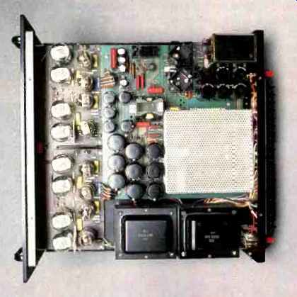
Interior space of the EA-2101 is about equally divided between power-supply and amplifier circuitry. A large p.c. board contains the power-supply circuitry. A portion of the circuitry that is prone to radiate is covered by a perforated metal shield. The two channels of actual amplifier circuitry are arranged end to end and take up about the front 25% of the chassis. These amplifier circuit boards are made of Teflon, as in the preamp. In the space that remains, to the right of the power-supply board, the output transformers are mounted to the chassis bottom. This unit is fairly light for its power output rating, because the switching power supply operates at a higher frequency than the a.c. line, allowing the use of a smaller power transformer, and because the chassis is aluminum. Having the output transformers along the right edge makes the amp a little unbalanced and somewhat unwieldy.
Metalwork for both units is very simple, consisting of a bent-up piece of aluminum that forms the rear panel, bottom, and front sub-panel, while a perforated metal piece is bent to form the top and sides. The front panel of each is a quarter-inch piece of aluminum. Incidentally, the chassis is made of aluminum in order to be nonmagnetic and to prevent distortion induced by skin effect.
Parts appeared to be of good quality. Although workmanship was good, some of the leads could have been dressed a bit more attractively. The amplifier circuit boards seemed a little flimsy when I pushed in the middle of the board. This could cause some potential breakage in shipment due to vibration. The same comments apply to the main signal board in the preamp. I thought at first that a standoff under the middle of these boards would help, but the manufacturer said that there already is such a support there, and that the boards only seemed unsupported because Teflon circuit boards are so flexible.
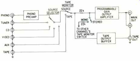
Fig. 1--Block diagram of Berning TF-12 preamp; see text.
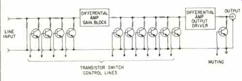
Fig. 2--Simplified schematic of the programmable-gain output amplifier shown
in Fig. 1.
Circuit Description
As can be seen in Fig. 1, a block diagram of the TF-12 preamp, the general topology is fairly straightforward except for the absence of the usual volume and balance controls following the "Mono/Stereo" switch. A departure from conventional signal-circuit practice is the use of an output amplifier with digitally programmable gain. The overall approach taken in the design of the programmable amplifier uses two amplifier gain blocks with two digitally controlled variable attenuators arranged as shown, in somewhat simplified form, in Fig. 2. The operating principle is to vary the amount of shunt resistance by turning on the various switching transistors and to have the resulting shunt resistance act against fixed series resistance. By arranging the value of the various shunt resistors and the logic states of the switch transistors, various attenuation settings can be achieved by changing control-line logic states. The Berning literature indicates that the control switches are out of the direct signal path; this is relatively but not strictly true, in my opinion. Although the nonlinearity of a turned-on switching transistor's "on resistance" is small compared to the linear resistance of the attenuator resistor that is in series with it, this non-linearity would still have some very small effect on the signal path.
The amplifier circuitry within the blocks is composed in each case of a single differential amplifier using 6DJ8 dual triodes. A differential topology was chosen, to be more immune to any effects o' the power supply and to get a large measure of distortion reduction without loop negative feedback. Operating conditions are somewhat different for the two amplifier blocks. The first stage has some cathode feedback and plate-load resistors of higher value than the second, or output, block. In the output differential amplifier, the value of the plate-load resistor is in the low tens of kilohms, and a feedback loop from the tube's output plate back to its own control grid reduces the net output impedance to about 3 kilohms Incoming supply voltage for the four differential-amplifier stages (two per channel) is dropped by decoupling resistors from the power supply's 190V output to about ± 160 V at the actual circuits.
Obviously, suitable bypass capacitance is present at all of the decoupled supply points. Another interesting but not unprecedented feature is that each amplifier block is capacitor-coupled at its input and direct-coupled at its output.
Solid-state op-amp circuitry acts as output offset servos, keeping d.c. offset at each block's output to low values.
The phono circuitry looks to be somewhat more conventional. Operating from a positive supply only, the first stage consists of both halves of a 12AX7 in parallel, acting as a common-cathode amplifier. Output of the first stage is capacitor-coupled to a second stage, again configured as a common-cathode amplifier; it uses one-half of a 12AT7 tube. An RC equalization network is connected from the output of the second stage back to the first stage's cathode resistor, thus causing the required RIAA curve to be generated by feedback equalization. The other half of the 12AT7 tube is used for the tape output buffer. Configuration is as a cathode follower with capacitor-coupled input and direct coupled output. An op-amp servo operates on the input-grid potential so as to keep the d.c. output close to 0 V. I am not going to delve into the specific details of the power supply, other than to say that it appears to be a rather sophisticated design. It uses a half-bridge topology to drive the main high-frequency power transformer, rather than the more usual push-pull drive.
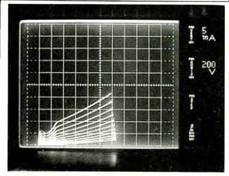
Fig. 3--Plate voltage (horizontal axis) vs. plate current (vertical axis)
of 6JN6 tube for normal pentode-connected operation, at several different
control-grid voltages differing by 2 V per step. Plate currents here and
in Fig. 4 are lower than they would be in actual output tube operation. Scales:
Vertical, 5 mA per div.; horizontal, 200 V per div.
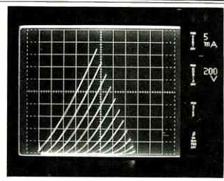
Fig. 4--Same as Fig. 3 but for Berning's screen-grid drive, with screen-grid
voltages varying by 5 V per step. Notice the even spacing between traces
and the resemblance to triode operation in the trace shapes at these low
levels.
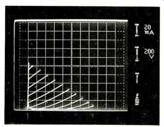
Fig. 5--Same as Fig. 4 but for medium currents and increases in screen-grid
voltage of 10 V per step.
Note the change of vertical scale to 20 mA/div.
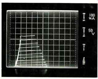
Fig. 6--Same as Fig. 4 but for high currents typical of output tube operation;
screen-grid voltage is changing here by 20 V per step. Note the low voltage
across the tube when driven sufficiently hard. Scales: Vertical, 100 mA/div.;
horizontal, 50 V/div.
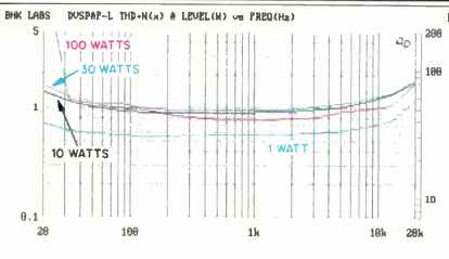
Fig. 7--THD + N vs. frequency and power, EA-2101 amp.
Fig. 9--Output and distortion residue for 10 watts out into 8 ohms at 1
kHz. The THD + N measured 1%.
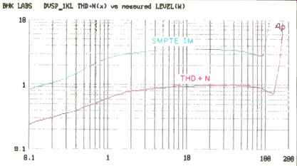
Fig. 8--THD + N for 1-kHz input, and SMPTE-IM distortion, vs. output power
for 4-ohm load.
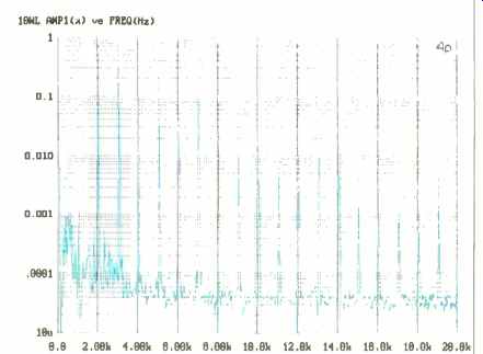
Fig. 10--Spectrum analysis of distortion residue shown in Fig. 9.
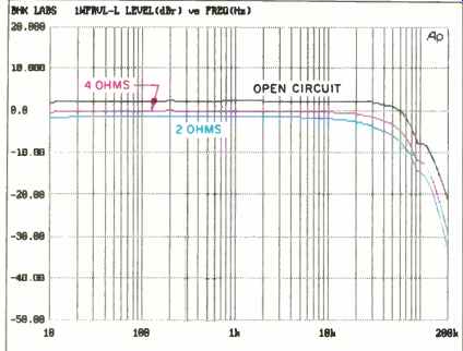
Fig. 11--Frequency response of EA-2101 vs. load.
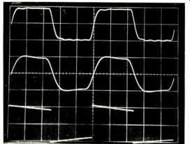
Fig. 12--Square-wave response of EA-2101 at 10 kHz into 8-ohm load (top
trace), 10 kHz into 8 ohms paralleled by 2µF (middle), and 40 Hz into 8 ohms
(bottom). Scales: Vertical, 5 V/div.; horizontal, 20 µS/div. for 10-kHz traces,
5 mS/div. for 40-Hz trace.
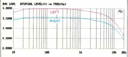
Fig. 13--Damping factor vs. frequency for 4-ohm load.
In the EA-2101 amplifier, let's start with the unique operation of the output stage. In most such stages, the input signals go to the control grids of the output tubes. When the output tubes are beam-power types or power pentodes (such as EL34s) with suppressor grids instead of beam forming plates, the screen grid is either tied to a regulated supply, tied to a primary tap on the output transformer (as in ultralinear operation), or tied to the plate of the tube when normal triode operation is desired. In each case, the screen grid has a high positive potential, and the control grid has a negative potential to control the overall current conduction through the tube. Looking at volt-ampere curves for output tubes reveals that, for a fixed control-grid voltage, the conduction is also a function of the screen-grid voltage. However, each volt of change on the control grid still has more effect on the output current than each volt of change on the screen grid does. What Berning has done is to set the control grid at the same potential as the cathode, by shorting these elements together! The idling screen-grid voltage is at some very low value to reduce the plate current to a very low value, 3.75 mA per tube. Four tubes in push-pull parallel are used in the EA-2101, so the idling plate current for an output stage is four times 3.75 mA, or some 15 mA. The reason the idling plate current can be so low is that the linearity of the tubes, when screen driven, is much better than when control-grid driven. Figures 3 to 6 show some of this in graphic form. Figure 3 is for a normal output tube when operated at lower currents. As can be seen from the uneven spacing between the traces in the figure, linearity is pretty lousy in this mode, which is why no one, including Berning, uses it with these tubes. By contrast, Fig. 4, which shows the low-current linearity of the same tube operated with screen-grid drive, is much better. Further, the traces look like triode characteristics at these current levels. Figure 5 shows the characteristics at somewhat higher levels. What is interesting is that the traces look like those of a normal triode but with both positive and negative grid voltages. If this were an actual triode, the curve that originates at the vertex of the vertical and horizontal axes would be for a grid voltage of 0, with the curves to the left of and above it representing positive voltages and those below and to the right of it representing negative voltages. Lastly, Fig. 6 shows the VI characteristics at the higher current levels that would be typical of full-power operation of the tube. Some of the other benefits of this mode of operation, besides linearity, are efficiency of operation and extended tube life: Thanks to the low idling plate current, the a.c. power drawn off the line at idle should be less than with conventional output stages. The lower idling plate dissipation also means that the tube runs much cooler and will therefore last longer.
As nice as all this looks, there is a price to pay, and that is in the drive required to fully modulate such an output stage.
I would estimate that the amplification factor of such a stage might be five to six times lower than in normal tube operation. This means that the voltage gain required to get full power would be that much greater, and perhaps just as important, the amount of signal swing at the controlling screen grid would be a lot higher too-some 200 to 400 V peak. Therefore, more stages of amplification are likely to be required in such a scheme. Sure enough, the EA-2101 has three differential triode gain stages in cascade. The last gain stage drives a cathode follower that is direct-coupled to the output-stage screen grids. One thing I failed to mention is that the input impedance at the screen grid is somewhat nonlinear and not the high impedance seen at the control grid in normal tube operation. The cathode follower helps to drive the output-tube screen grids with reasonable linearity. Of the four front-end stages, the second and third are direct-coupled and the others are capacitor-coupled.
Cathodes of the first and third differential voltage-amplifier stages are tied together for no local feedback and have tail resistors down to a 180 V source. Feedback resistors are used in the second voltage-amplifier stage, and in fact, a push-pull feedback loop from the output tube plates is taken back to this stage's cathodes. The control-grid circuits of the cathode-follower driver stage have separately adjustable bias control of the screen-grid potential of the output stage tubes. As mentioned previously, the input can be driven balanced or unbalanced with equal ease.
The power supply is a resonant, switching type. As discussed, the various outputs of this supply are regulated, even the +700 V to the output stage. All of the tube heaters, including those in the output tubes, are operated off regulated d.c. A number of safety features are unique to the EA 2101. The power supply has a multi-step, soft-start sequence that reduces the inrush current when the amp is first turned on. This eliminates burning of the power switch's contacts, as the main current draw is delayed about a second after the switch is closed. Low line voltage is sensed in this power supply, and if the line voltage is below a certain threshold, the unit won't turn on. Further, when the EA-2101 is operating and the line voltage drops to a sustained voltage below the nominal value, the power supply shuts down and must be manually restarted. A protection circuit monitors the current level in each pair of output tubes; if current is judged to be excessive, the power supply goes into a foldback mode, protecting the output tubes and the power supply. Overall, a very interesting circuit.
Measurements
Before measuring the EA-2101, I had been listening to it with the output windings strapped in a series-parallel mode for 4-ohm loading. I left it in that connection for the first tests I made, which were for distortion characteristics. The distortion shown is for the left channel, an arbitrary choice, as both channels behaved very much alike. Figure 7 shows how THD + N varies as a function of power output and frequency. While the amount of distortion is high, it doesn't rise much with increasing frequency above 1 kHz. At rated power of 100 watts, distortion rises rapidly below 30 Hz, presumably due to onset of output transformer saturation.
Figure 8 illustrates how 1-kHz THD + N and SMPTE-IM distortion vary with power output. The results for operation with the output windings in series and with 8-ohm loads on the 8-ohm taps remained essentially as shown. What is interesting to me is that the amount of distortion is pretty constant with power above 2 or 3 watts and that the IM is about four times the THD over most of the power range. The latter is a classic, theoretical relationship between the two kinds of distortion when the distortion characteristic is simple and does not change with level. The nature of the distortion residue above 3 watts is what I call "gain reduction at the origin," or crossover-type, distortion. This kind of distortion is worse at low levels and usually decreases as the power goes up because the nonlinearity is an increasingly smaller fraction of the waveform's amplitude. In contrast, this amplifier has lower and simpler distortion below 3 watts and essentially constant distortion above that level.
Figures 9 and 10 show, respectively, the THD residue at 10 watts into 8 ohms on the 8-ohm tap and its corresponding spectral nature. There is a considerable amount of higher order harmonic residue here, although the magnitude does decay with harmonic order. A conventional tube output stage operated at this very low idling current would have a lot more distortion than the Berning design. Even so, this characteristic and amount of distortion could give the amp's sound a measure of brightness and harshness.
Voltage gain was measured next. With the output strapped in the "normal mode" (all the secondary windings in series) and with 8-ohm loads on the 8-ohm taps, gain was 30.9 and 30.6 dB for left and right channels, respectively.
Corresponding IHF sensitivities were 82.5 and 85 mV. Frequency response at an output level of 1 watt is shown in Fig. 11 for open-circuit, 4-ohm, and 2-ohm loading on the 4-ohm tap. This presentation provides insight to a number of things. First, the magnitude of output impedance can be judged by how far apart these curves are spaced; since the voltage output doesn't vary much with loading, the output impedance is low. Second, the degree and uniformity of high-frequency damping is shown by the consistent shape of the curves above, say, 30 kHz. The amount of output impedance is typical for a tube output stage with output transformers, and the high-frequency damping is nicely controlled as a function of loading. Rise- and fall-times at a ±5 V output level into 8 ohms were about 8 µS. In the square-wave pictures (Fig. 12), the 10-kHz trace (top) is nicely damped in terms of overshoot, but some ringing can be seen at about 100 kHz, which may relate to the response glitch in this frequency region seen in Fig. 11. Behavior with an added 2-µF load (middle trace) is quite good, with overshoot and ringing well controlled. The amount of tilt in the 40-Hz trace (bottom) is reasonable but not as low as I have seen in some other tube amplifiers.
Damping factor versus frequency for the series-parallel connection of output windings is shown in Fig. 13, referenced to a 4-ohm load. With the windings all in series configuration and the measurement made at the 8-ohm tap, the damping factor remained about the same.
Interchannel crosstalk was found to be greater than 80 dB down in both directions, which is quite good.
Output noise as a function of measurement bandwidth is listed in Table 1. Leakage of the switching frequency in the power supply makes up most of the wideband reading.
Although it is higher in the left channel, it is still very low in absolute terms. With this high frequency removed by limiting the bandwidth to 22 kHz, the remaining noise in the left channel is mostly hum, which could be audible in some situations with high-efficiency speakers. The right channel is considerably better.
Even though the high-voltage supply is said to be regulated, the pulse power is slightly greater than the steady-state power in the EA-2101. Consequently, dynamic headroom measured 156 watts, or 1.9 dB above rated continuous power, and clipping headroom was 145 watts, or 1.6 dB, for 8-ohm loading on the 8-ohm taps. With a 1-ohm load on the 8-ohm tap and with one channel driven, a peak current of some ± 10 amperes could be obtained with the tone-burst signal for dynamic headroom. When the 1-ohm load was connected to the nominal 1-ohm tap (actually 0.89 ohm, one secondary winding alone), the available current before visible distortion set in was ± 15 amperes. If the secondary windings were all paralleled, the amount of available current would probably increase a little more.
A couple of miscellaneous notes on the amplifier: The a.c. line draw was about 2.1 amperes at idle and 6.4 amperes when delivering 100 watts per channel. For the EA-2101's low computed idling plate dissipation of some 10 watts per channel, 2.1 amperes strikes me as a lot of input line current for a high-efficiency switching power supply. Berning's specs indicate an idling power draw of some 130 watts. I computed the power drawn by the tube heaters as being about 90 watts (120 V times 2.1 amperes equals 252 VA). Either this power-supply design has a rather poor power factor (more likely) or the 130-watt figure is low.
The TF-12 preamp's gain and sensitivity for the various inputs and outputs are presented in Table II. A minor glitch in the operation of the gain-control system made the gain of the left channel 1 dB higher than that of the right when the attenuations read the same on the front-panel indicators.
Because I couldn't decide which channel's indicator was correct, I equalized the gains by setting the left channel's display to indicate 1 dB more than the right channel's. I then used this setting for the preamp gain measurements shown in the Table.
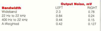
Table I-Output noise, EA-2101 amplifier. The IHF S/N was 76.3 dB for the
left channel and 87.2 dB for the right channel. Switching noise from the
power supply was the main contributor to the left channel's wideband reading,
while harmonics of the 60-Hz line frequency dominated the other left-channel
measurements.
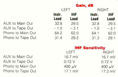
Table II--Gain and sensitivity, TF-12 preamplifier.
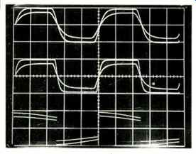
Fig. 14--Square-wave response of TF-12 line amp section, for instrument
and IHF loads.
(The smaller trace in each overlaid pair is for IHF loading.) Top trace is for 20 kHz at 0-dB attenuation, middle trace is 20 kHz at 30-dB attenuation, and bottom trace is 20 Hz at 0-dB attenuation. Scales: Vertical, 5 V/div.; horizontal, 10 µS/div. for 20-kHz traces, 10 mS/div. for 20-Hz trace.
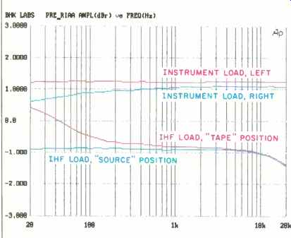
Fig. 15--RIAA equalization error; see text.
Impedances of the main and tape outputs were near the claimed value of 3 kilohms, about 2.9 kilohms for the main outputs and about 2.6 kilohms at tape out.
The two channels of the line amplifier section behaved pretty much alike in regards to distortion, so I arbitrarily decided to discuss only the results for the left channel.
Maximum output at the visual onset of clipping was 7.8 V with either instrument or IHF load. Total harmonic distortion plus noise was not easy to measure, as some amount of power-supply switching frequency was present on the main outputs. Interestingly, there was more of this leakage with full line amp gain than with normally used settings of attenuation. When I used a low-pass filter to eliminate the high frequency switching leakage, THD N with instrument load was less than 0.1% at 2 V output up to about 2 kHz, rising to about 0.2% at 10 kHz. With an IHF load, the distortion was more than four times as great but did not rise as much at high frequencies. This line amp is a competent driver and does pretty well into a 10-kilohm load, which a lot of tube preamps can't begin to handle.
How accurate are the actual output attenuations compared to the front-panel readout values? Generally pretty good, with no more than ±0.5 dB of error down to 70 dB of attenuation. Channel-to-channel attenuation settings were even closer, within 0.3 dB down to 70 dB of attenuation once the initial 1-dB imbalance was adjusted.
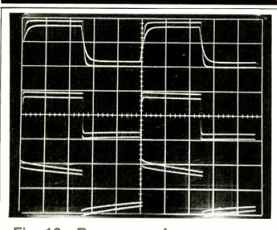
Fig. 16--Response of phono preamp section to pre-equalized square waves
at (top to bottom) 10 kHz, 1 kHz, and 40 Hz.
Overlaid traces show effect of instrument and IHF loads; smaller trace in each pair is for IHF loading. Scales: Vertical, 1 V/div.; horizontal, 20 µS/div. for 10 kHz, 200 µS/div. for 1 kHz, and 5 mS/div. for 40 Hz.
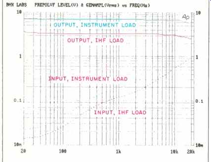
Fig. 17--Phono overload vs. frequency; see text.
Table III--Output noise, TF-12 line amp section, at two attenuation settings. The IHF S/N at-30 dB was 71.5 dB for the left channel and 65.7 dB for the right channel.
Interchannel crosstalk had a characteristic that was flat up to about 100 Hz; it then rose at a 6-dB/octave rate. With gain at maximum, crosstalk was worse in the right-to-left direction, being more than 80 dB down up to 200 Hz and, on that 6-dB/octave slope, down about 41 dB at 20 kHz. The left-to-right direction was about 10 dB better. When attenuation was set at 30 dB, a more likely setting, crosstalk was more symmetrical in the two directions and about the same amount as in the left-to-right direction just mentioned. Line amplifier crosstalk was in phase, meaning that, for a pulse on the driven channel, the crosstalk leakage's leading edge is in the same direction as the driving pulse.
Rise- and fall-times of the output amplifier were measured at maximum gain and at an attenuation of 30 dB. At maximum gain, rise- and fall-times at an output level of-5 V were about 5.8 µS with instrument loading and 9.0 µS with IHF loading. (My instrument load is about 90 kilohms in parallel with about 200 pF, and the IHF load is 10 kilohms in parallel with 1,000 pF.) At the 30-dB attenuation setting, the figures were 2.8 and 7.0 µS. Oscilloscope pictures of 20 kHz square waves at these two gain settings, and of a 20-Hz square wave at 0-dB attenuation, are shown in Fig. 14. Each of the trace pairs is for instrument and IHF loading; the smaller amplitudes in each pair are for the IHF load. Evident in the figure are the nicely damped exponential edge shapes. The effect of the IHF load's 1,000 pF on the high frequency response can be seen, as well as the change in rise-time between the two attenuation settings. In the bottom trace (20 Hz), the amount of tilt is reasonable, and the IHF loading has no particular effect on frequency. The overall waveshape suggests a very mild, shelving bass boost, since the trace as seen from the 0-V axis is not convex.
In testing for output noise, I decided to measure the output magnitude itself rather than my usual convention of referring it to the input of the line amplifier. Results are shown in Table III. Although amounts of noise per se in the audio band are perfectly acceptable with the 30-dB attenuation setting, which is representative of what the unit does under normal conditions, I feel that the amount of switching noise indicated by the wideband reading with the attenuation set at zero is a bit much from a technical standpoint.
Who knows, though; it might dither the following power amplifier and make it sound better! RIAA equalization error of the phono stage is plotted in Fig. 15 for left and right channels with instrument loading; these are the top two curves in the figure. Equalization accuracy of the left channel is very, very good. Shown in the bottom two curves is the effect of IHF loading and, interestingly, the effect of switching the monitor to tape input, thereby unloading the phono preamp output from driving the following circuitry. This rise in the low-end response also occurs for higher impedance loading of the tape output on phono function. It does have a subtle consequence that you might not think about, in that when you are recording from phono onto tape and are monitoring the tape, the recorded low-frequency response would change by the amount shown in the figure.
Figure 16 illustrates response to pre-equalized square waves through the phono section. Results are shown for the less flat (right) channel. Again, the effects of IHF loading are seen in the multiple traces for each frequency. Generally speaking, the waveforms look pretty good. Asymmetrical behavior, the result of high-frequency overload, started to set in at about ± 1.5 V output, 50% greater output than shown in the figure.
Distortion behavior of the phono circuit, like that of the line amplifier, was very consistent between channels, so subsequent discussion on distortion will be for the left channel.
The phono circuit's THD + N was quite uniform over the audio range with either instrument or IHF loading. At 1 V output, it was on the order of 0.018% with the instrument load and rose to about 0.5% with the IHF load. Like the line amplifier, the phono circuit will drive 10 kilohms with higher distortion but otherwise with few ill effects.
Figure 17 shows one of the many neat things that I can easily configure my fabulous Audio Precision measurement machine to do. This is a plot of phono overload as a function of frequency, showing the attainable output level as a function of frequency and loading at a specified regulated distortion level (in this case, 3%), and the corresponding input level to the phono stage. As I have mentioned in past reviews, ideal behavior is for the output level to be flat with frequency. The TF-12 comes very close to this ideal. As can be seen, the 1-kHz overload level is greater than 100 mV. Slick, huh? Interchannel crosstalk in the phono stage had some strange but good properties: The high-frequency crosstalk level was puzzlingly independent of terminating source impedance, and the low-frequency crosstalk level was better with open-circuit termination! The similarity of crosstalk behavior in the two directions was good. The overall amount was on the order of 70 dB at the low end, dipping to a minimum of some 87 dB in the middle of the audio band and coming back up again to 70 dB or so at the high-frequency end of the audio range.
Phono noise referred to input is shown in Table IV. The wideband measurement is mostly r.f. or switching-frequency leakage. The amount of in-band noise is satisfactorily low tor moving-magnet cartridges, but hiss would likely intrude with moving-coil cartridges of low to medium output (50 to 200 µV) if a step-up device isn't used.
A few final notes on the preamp: Overall phono, line input, and line amplifier polarities are noninverting. A muting circuit operates to mute the main output, but as is typical in most preamps, the phono preamp is not muted. The a.c. line draw was about 0.24 ampere at 120 V input.
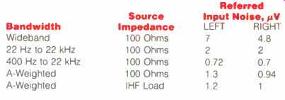
Table IV--Phono section noise, referred to input. Switching noise dominated
the wideband and A-weighted 100 ohm measurements for both channels and the
left-channel A-weighted figure for IHF loading. The IHF S/N was 72.4 dB for
the left channel and 74.0 dB for the right.
Use and Listening Tests
Signal sources used to evaluate the Berning gear included an Oracle turntable fitted with a Well Tempered Arm and Spectral Audio MCR-1 Select MC cartridge, a Magnavox CDB-560 CD player feeding a Wadia 2000 decoding computer, a Nakamichi 250 cassette deck, a Nakamichi ST-7 tuner, and a Technics open-reel recorder. My reference setup includes a selector-switch and switched-attenuator unit that I built; my reference tube preamp is one selectable source. Other high-level sources, like the CD system or the Vendetta Research SCP-2B MC phono preamp that I use for playing records most of the time, are selected for listening with this control unit. Power amps on hand included a pair of Carver Silver Sevens, my reference EAR 519s, an Air Tight ATM-1, and a reference set of Cary Audio CAD-50sl-s. A Gryphon Audio preamp was in residence for the latter part of the review period. Speakers used were pairs of the Spica Angelus, Siefert Research Magnum Ill, and Martin-Logan Monolith III. I also used experimental two-way systems loaned to me by Arnold Nudell.
I listened to the EA-2101 amp on all of the speakers mentioned above and would characterize its sound as very spacious and detailed, with a tendency to some upper midrange irritation or edginess. Compared to some of the tube amps I had on hand, the EA-2101 sounded a little underdamped in the low end. Every time I would hook it up, I would say, "Wow, listen to that!" But after using it for a while, it would begin to irritate me. I should mention that I am perhaps overly sensitive to this phenomenon; others could just as well respond only positively to the amp's qualities.
I approached the sonic evaluation of the TF-12 preamp by comparing the sound of the line amplifier with my reference input selector switch and level attenuators. I can report that the TF-12 did a good job of preserving the music. The differences I noted were sins of omission, subtractive in nature. Detail and space were softened a bit, and the overall believability of the music was accordingly reduced. Playing vinyl discs through the whole preamp produced a nonirritating sound that was perhaps a shade too soft.
It sure was nice to have the remote volume control when using this preamp! I am beginning to think that being able to get the "just right" volume at the listening position via a remote is really almost a necessity in order to get the most out of your system. When I used the remote muting function, there was a mild pop when coming out of mute.
When I paired the Berning units together, their individual characteristics were complementary, and the overall sound was very listenable and musical indeed. The amplifier's tendency to be slightly irritating came through on some material but not nearly as much as when used alone. In summary, I think the Berning gear is technically innovative and that it produced some very good sound in my environment. I would definitely recommend going out and giving this amp and preamp an audition.
-Bascom H. King
(Source: Audio magazine, Dec. 1991)
Also see: Conrad Johnson Premier Five Amplifier (Aug. 1986)
Crown Model DL-2 Digilogic Control Center (Mar. 1979)
= = = =