Manufacturer's Specifications:
Power: 200 watts continuous into 4, 8, or 16 ohms, 30 Hz to 15 kHz, at 1% THD or IM.
Sensitivity: 1 V for full rated power.
Small-Signal Distortion: 0.05% at mid-band.
Frequency Response: 20 Hz to 20 kHz, +0.- 0.5 dB.
Hum and Noise: 96 dB below full rated output.
Input Impedance: 100 kilohms.
Dimensions: 19 in. W x 9 in. H x 20 1/2 in. D (48.3 cm x 22.9 cm x 52 cm).
Weight: 81 lbs. (36.8 kg).
Price: $3,000 each.
Company Address: 2800R Dorr Ave., Fairfax, Va. 22031, USA.
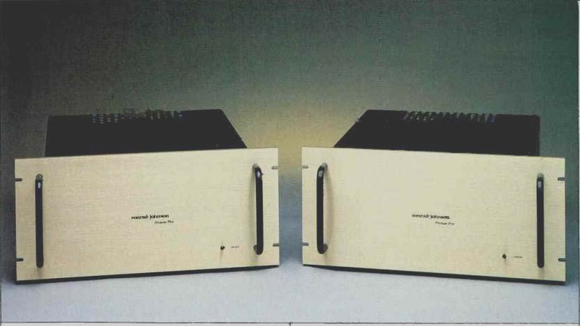
The conrad-johnson Premier Five is a 200-watt, mono, vacuum-tube power amplifier. It is quite large and heavy, and surely will whet the appetite of any tube-electronics lover. I was very pleasantly surprised, a number of months ago, to have a pair of these beauties arrive on my doorstep.
I decided that it would be a good idea to review them, as I had spent a good deal of time listening to two other pairs on Infinity RS IB loudspeakers.
Physically, the Premier Five is built more or less like older tube amplifiers, with a main chassis; a large, thick, rack width front panel; side pieces, and a top cover. However, instead of using point-to-point wiring between tube sockets and other components, it utilizes a large p.c. board which has most of the interconnections via p.c. traces. The tube sockets are mounted on the p.c. board, and the tubes stick up through holes in the top surface of the chassis. In addition to the holes for the eight output tubes and three front-end tubes, there are holes for a bias pot and a bias-indicator LED for each output tube. The only problem with this construction is that the p.c. board must be partially unwired and swung out if one wishes to replace components on it.
Mounted on the chassis are four large electrolytic capacitors for the power supply, a huge power transformer, and a not-so-huge but still substantial output transformer. On the rear surface of the chassis are a large, four-terminal screw barrier strip appropriate for heavy speaker wire, a plate-current fuse with an LED fuse-out indicator, an RCA signal-input jack, a power-line fuse, and the power cord. The front panel bears a pair of handles and a non-illuminating power switch.
Construction and parts quality on this amp are very good.
Reliability is also good, judging from my own experience with the pair under review and with the two pairs owned by Infinity which I had previously auditioned.
Circuit Description
The circuit topology of the Premier Five is similar to that of many older tube designs. The first stage is a grounded-cathode amplifier with two resistors in series from cathode to ground. The signal input is direct-coupled to the grid of the first stage through a 1-kilohm series resistor. Input impedance is set by a 100-kilohm resistor between input and ground. The plate of the first stage is direct-coupled to the grid of the second-stage tube, which is operated as a grounded-plate or cathode follower. The first and second stages use the two halves of a 5751 twin triode tube. Plate-supply voltage to these stages is about 400 V d.c.
The output of the cathode-follower second stage is direct-coupled to the grid of the phase-inverter stage, which is a "long-tailed pair" or differential amplifier. Each tube in the phase-inverter stage is a 6CG7 tube, whose two halves are connected in parallel. The plate outputs of the phase-inverter stage are two equal-amplitude, opposite-phase signals.
These are each coupled through four separate capacitors into the grid circuits of four EL34 tubes, which are connected in parallel. Plate-supply voltage for the phase-inverter stage is about 430 V d.c.
This output stage is operated in an ultra-linear connection, with the screen grids of the output tubes fed from taps on the output transformer's primary winding. The B+ for the output stage is about 500 V d.c. Output-stage quiescent current is about 360 to 400 mA.
Output-tube bias is set by a neat arrangement that, to the best of my knowledge, conrad-johnson has used on all their tube power amps. Output tube current is sampled across a 20-ohm resistor between each cathode and ground. An op-amp comparator circuit for each output tube compares the cathode voltage to a fixed reference voltage. Each op-amp comparator output is connected, via an indicating LED, to ground. If a particular cathode voltage is higher than the reference, the output of that comparator goes high, turning on the indicator LED. After a suitable warmup of 15 to 30 minutes, biasing procedure requires one to turn the bias pot for each tube until its LED comes on, and then back it off until the LED just goes out. This is simple and neat, though personally, I would rather have a front-panel plate-current meter and switch to select each tube, along with bias pots accessible on the front panel, as on the Audio Research D150 and the older Marantz Model 9.
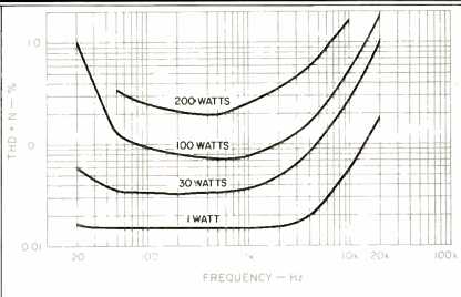
Fig. 1--THD + N vs. frequency for four power levels, with 8-ohm load on
8-ohm tap.
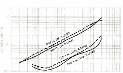
Fig. 2--SMPTE IM (upper curves) and THD + N (lower curves) vs. power for
8-ohm loads on 8-ohm taps and 4-ohm loads on 4-ohm taps. THD + N is for a
1-kHz test signal, with distortion products measured from 400 Hz to 80 kHz.
Overall negative feedback is taken from the output transformer secondary at the 16-ohm tap, through a 5 1-kilohm of series resistor, back to the junction point of the first-stage cathode resistors.
In the power supply, the high-voltage secondary is full-wave rectified. A capacitor input filter is formed by two 1,300-µF, 350-V capacitors placed in series. Across each of these caps is a 100-kilohm, 2-watt resistor. The resistors equalize the d.c. voltage drops across each of the capacitors, and form a bleeder to discharge the capacitors when the power is turned off-definitely dangerous energy storage here. A series inductor, 0.32 henry at 600 mA, couples the peak-rectified d.c. into another capacitor formed by two 3,300-µF, 350-V units in series. Again, 100-kilohm, 2-watt resistors are placed across these capacitors. A parallel combination of two 2-µF, 600-V film capacitors and one 0.15-µF, 630-V film capacitor are placed in parallel with the final electrolytic filter capacitor. The final filtered high voltage is fed to the center tap of the output-transformer primary winding through a 3-ampere fuse that is paralleled by an LED (in series with a limiting resistor) which indicates when the fuse is blown.
The final filtered high voltage also feeds two solid-state zener-follower voltage regulators that supply the regulated voltages of the front-end stages. Across the output of the regulator that feeds the input-amplifier stage are eight 0.15 uF film capacitors. The regulator that feeds the phase-inverter stage is bypassed by a parallel combination of four 1-uF and two 0.15-µF film capacitors.
Another winding on the power transformer is half-wave rectified and filtered, and feeds two separate zener-follower regulators that provide -48 V bias supplies for each half of the output stage. Like the high-voltage supplies, these bias supplies are full of good-quality film bypass capacitors.
A third secondary winding on the power transformer is full-wave bridge rectified and capacitor-filtered to feed smoothed d.c. to the heaters of the front-end tubes. A fourth secondary winding is half-wave rectified to a plus-and-minus supply which provides the supply and reference voltages for the op-amp's bias indicator circuits. A fifth (and final) secondary winding provides 12.6 V a.c. to power the heaters of the output tubes.
To sum up the Premier Five's circuitry: The amplifier circuit itself is fairly straightforward, with the exception of the cathode-follower buffer between the first amplifier stage and the long-tailed-pair phase inverter. The power supply has a lot more filter storage capacitance than older tube-amplifier designs. This, in conjunction with the voltage regulators powering the front-end circuitry, most likely helps keep things more solid-especially under large-signal conditions.
The liberal use of low dielectric-absorption, film bypass capacitors throughout the power supply probably helps sonic performance considerably.
Measurements
The first step in measuring the Premier Fives' performance was to re-bias the output tubes to the correct idling current at an a.c. line voltage of 120 V. This current, by the way, is 45 to 50 mA. In my house, the line voltage is more like 112 to 114 V with the amps on. Before I re-biased the amps, I measured the mid-band power, at the onset of clipping, with 112 V from the power line. This worked out to about 180 watts.
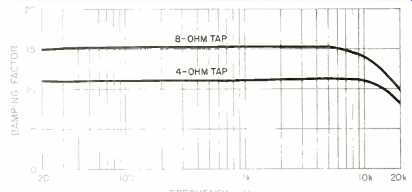
Fig. 3--Damping factor vs. frequency, measured at 8- and 4-ohm taps.
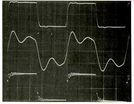
Fig. 4--Response to 10-kHz square wave.
Top trace is with 8-ohm resistive load on the 8-ohm tap; middle trace is with 2-p.F capacitance across 8-ohm load, and bottom trace is for open circuit (note marginal stability). Scales: Vertical, 5 V/div.; horizontal, 20 µS/div.
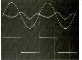
Fig. 5--Top trace: 10-watt, 1-kHz sine wave with distortion products (predominantly
even harmonic) shown as residual trace behind it.
Bottom trace: 40-Hz square wave, showing excellent low-frequency response. Both signals delivered into 8 ohms. Scales: Vertical, 5 V/div.; horizontal, 5 mS/div.
Voltage gain, with an 8-ohm load on the 8-ohm tap, was 36 x or 31.1 dB, which is some 5 dB higher than the usual power-amp gain of 26 dB. For the 4-ohm tap, gain was 26.5 x or 28 dB. 1HF sensitivity for 1 watt out into 8 ohms was 78.5 mV.
Figure 1 shows THD + N versus power and frequency, for 8-ohm loads on the 8-ohm taps. As can be seen, distortion rises above 1 to 2 kHz for all power levels shown. At higher power levels, distortion also rises at low frequencies.
At 20 Hz, the amp could not produce 200 watts output due to output-transformer saturation.
Figure 2 shows THD + N (measured from 400 Hz to 80 kHz, for a 1-kHz test signal) and SMPTE-IM distortion, for 4- and 8-ohm loads on their respective taps. The amp's behavior on the 16-ohm tap is about like that on the 4-ohm tap. For some reason that I can't figure out, the 8-ohm THD at 200 watts shows onset of clipping, but distortion with 8 ohm loading is lower below 200 watts than with either 4- or 16-ohm loading. With either 4- or 16-ohm loading, the THD residue produced at 200 watts output does not exhibit onset of clipping.
Damping factor versus frequency is shown in Fig. 3 for the 4- and 8-ohm taps. Damping factor is higher yet on the 16-ohm tap, because the feedback is taken from this tap on the secondary of the output transformer.
Rise- and fall-times into an 8-ohm load were 3.5 uS at ±5 V output. Oscilloscope photos for various conditions are shown in Figs. 4 and 5. The top trace of Fig. 4 is for a 10-kHz square wave into 8 ohms, driven from the 8-ohm tap. The middle trace is with 2µF of capacitance paralleled with the 8-ohm resistive load. The bottom trace is for an open circuit; stability here is marginal. Square-wave performance on the other taps is similar, but not the same in terms of ringing and overshoot. The top trace of Fig. 5 shows the nature of the harmonic residue, which is predominantly even harmonic, at 10 watts output at 1 kHz. The lower trace shows excellent low-frequency response with a 40-Hz square wave.
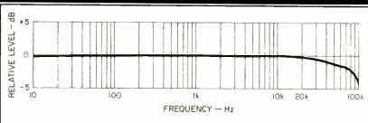
Fig. 6--Frequency response at 1 watt output into 8-ohm load.
Frequency response at 1 watt output, for 8-ohm loading, is shown in Fig. 6. The IHF signal-to-noise ratio was found to be-82 dB. IHF dynamic headroom measured 218 watts or 0.37 dB, and IHF clipping headroom was 205 watts or 0.11 dB; both were measured with 8-ohm loading and 120-V a.c. line input.
Peak current into a 0.1-ohm load on the 4-ohm tap, using the IHF dynamic-headroom test signal of 20 mS on and 480 mS off at 1 kHz, yielded ±22 amperes before visible distortion occurred.
Summing up on measurements: The Premier Five tube amplifier has higher distortion figures near full power than most solid-state power amplifiers, although at low to medium power levels it is satisfactorily low. High-frequency stability might be a problem with a load that presents a high impedance at ultrasonic frequencies. My only actual experience as evidence of this occurred when driving an Infinity IRS speaker, with its tweeter disconnected temporarily for test purposes. A buzz in the midrange drivers suggested that the amp was oscillating under this abnormal condition.
Use and Listening Tests
A comment on my personal preference or bias is in order here: Some of my reviews may give the impression that I don't care for solid-state gear and that I prefer tube equipment. I would like to clarify this. Good tube equipment, for me, simply re-creates (or creates, if you will) a more believable, emotionally involving musical experience. Where tube equipment gets it more right is in the areas of spaciousness, depth of image in the sound field, and instrument tonality.
Thus far, solid-state gear doesn't quite measure up in my opinion, although the gap is narrowing. I do like to use solid-state equipment because of its long-term reliability, stability of characteristics, lower power consumption, etc.
With this said, on to my evaluation of the Premier Five amplifiers' sonics.
As previously mentioned, I had the opportunity to hear two other pairs of Premier Fives, in the Infinity Systems sound room, on RS IB and IRS loudspeakers. The Infinity system uses a Mitchell A. Cotter turntable with a Goldmund tonearm and Koetsu Onyx cartridge. The resident preamplifier is an Audio Research SP10. With Premier Fives driving the midrange and tweeter sections of a pair of RS IBs, the sound of this system is very good indeed. I have listened to a good number of transistor amplifiers on this system; in comparison to the Premier Fives, they all sound variously less dimensional, more irritating, and ultimately less musical to my ears.
I have heard the personal system of Arnold Nudell, Infinity's president, a number of times. The signal source in this setup consists of an Otari professional open-reel recorder, playing low-generation copies of master tapes, with or without transformerless Dolby A NR units. The signal from the Otari is fed, via a dual 500-ohm volume control, into the bass amplifier and crossovers of an IRS speaker system.
Nudell uses Premier Fives to drive the midrange and tweeter panels. Reproduction is stunningly believable, which tells me that the Premier Fives are incredible amplifiers.
In my less lofty home listening environment (using an Infinity air-bearing turntable, Koetsu's new EMC-1B cartridge, Infinity RS IIB speakers, and Stax SR-X/Mk3 head phones), I have found the Premier Fives to be ultimately satisfying. I keep trying other amplifiers and when I go back to the Fives, my reaction is, "Ahhh, all right!" Even my super-critical associate, Geoff Cook, concedes that they are "pretty good amps." The only other power amplifiers that have satisfied me as these do are the Marantz 9s, which sound a little softer and sweeter in the high end and not quite as solid in the bass. Of course, the 9s are no longer commercially available, whereas the Fives are. I like the Premier Fives very much, and would recommend that any one who can afford them give them a serious audition.
As a concluding point, I wish I could quantify with some measurements why the Premier Fives sound so good. As a measurer, I don't yet have a clue. This is frustrating, and I hope to ultimately find out why. In the meantime, I have no trouble turning off the rationalist, the language-oriented, measurer part of me, turning on my ears, the ultimate measurer, and enjoying the music.
-Bascom H. King
(Source: Audio magazine, Aug. 1986)
Also see:
Conrad-Johnson Premier Seven-A Preamp and Evolution 2000 Amp (Jun. 1992)
David Berning EA-2101 Amp & TF-12 Preamp (Dec. 1991)
Counterpoint SA-220 Power Amp (Jul. 1990)
Classic Audio CA260 Dual Mono Amplifier (Nov. 1989)
= = = =