Manufacturer's Specifications:
Preamp:
Frequency Response: RIAA, ±0.25 dB, 20 Hz to 20 kHz; bandpass, 2 Hz to beyond 100 kHz.
Gain: Phono. 40 dB; line, 29 dB.
Phono Overload: 150 mV at 1 kHz.
Distortion at 1 V Out: Less than 0.25% THD or IM.
S/N: Phono, 84 dB below 10 mV input; line, 97 to 98 dB below 2.5 V output.
Maximum Output: 20 V rms.
Output Impedance: Less than 200 ohms.
Dimensions: Control unit, 19 in. W x 7 in. H x 16 in. D (48.3 cm x 17.8 cm x 40.6 cm); power supply, 19 in. W x 3 1/2 in. H x 15 3/4 in. D (48.3 cm x 8.9 cm x 40 cm).
Weight: 60 lbs. (27.3 kg).
Price: $8,950.
Amp:
Power Output: 200 watts rms per channel from 20 Hz to 20 kHz at no more than 1% distortion, both channels driven into 8 ohms.
Frequency Response: 20 Hz to 20 kHz, ±0.5 dB.
Sensitivity: 900 mV for full output.
S/N: 96 dB below full output.
Input Impedance: 100 kilohms.
Dimensions: 19 in. W x 10 1/2 in. H x 22 1/2 in. D (48.3 cm x 26.7 cm x 57.2 cm).
Weight: 114 lbs. (51.8 kg).
Price: $4,995.
Company Address: 2800R Dorr Ave., Fairfax, Va. 22031.
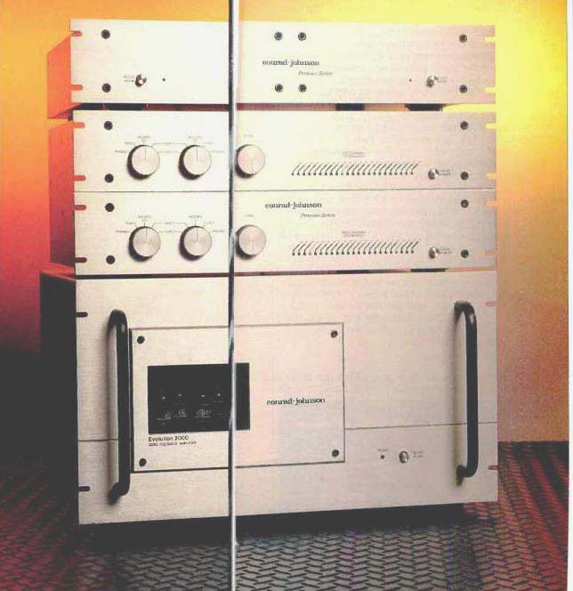
I was filled with pleasurable anticipation when I received these current top-of-the-line conrad-johnson components. The Evolution 2000 is a hybrid power amp using tubes for the front end and MOS-FET semiconductor devices for the transformerless output stage. The Premier Seven-A preamp uses all-tube amplification and solid state power-supply regulation. Both components have thick, gold-anodized front panels and are very attractive, well-made pieces of gear.
The Evolution 2000 amplifier looks like, and is similar in size to, conrad-johnson's previous all-tube models but with an obvious front-panel difference:
A window that shows the front-end tubes, so you can bask in their warm glow when the unit is running. The front panel also sports a pushbutton power switch, a red LED pilot light, and a pair of handles. Most of the amplifier's rear surface is taken up by heat-sink fins, with a vertical space between them for connections. From top to bottom are a pair of Tiffany phono connectors for signal input, a row of four fuse-holders for the positive and negative rails in each channel's output stage, a row of four five-way binding posts for speaker connection, and finally, at the bottom, the power cord and line fuse. Things are a little tight when connecting thick speaker cables, but it can be done relatively easily.

The Premier Seven-A comes in two pieces-preamp and external power supply. This is a big preamp! Both the preamp and power supply are dual mono, with separate a.c. line cords and power-supply interconnect cables for the individual channels. Front-panel controls for each channel include signal selectors for input and tape output, a stepped-attenuator volume control, and a "Mute" pushbutton at the far right. Volume-control settings for each channel are shown by horizontal rows of LED indicators. On the rear panel, for each channel, are Tiffany phono connectors for input and output, a multi-pin connector for the cable to the power supply, a gold-plated binding post for ground, and a phono-loading selector switch. Looking at the rear of the preamp makes its dual-mono construction obvious:
There is a gap between the bottom plate of one channel and the top plate of the other. In fact, if the side plates were unbolted, the two channels could be separated.
Internal construction of the preamp is a bit unusual. The signal circuitry is mostly on one p.c. board that takes up about half the internal area. This board is mounted to a metal frame that forms walls around it and is shock-mounted to the sides of the actual chassis. The manufacturer uses only film capacitors for coupling, filtering and bypass duty, and they take up most of the board area. A number of solid state regulators on the main board provide separate, regulated sources for each stage of the circuit. Four 6GK5 high transconductance triodes are mounted on the main signal board with what appear to be large rubber grommets slipped over each tube to reduce vibration and microphonics. Two of these tubes make up the output amplifier, while the other two are used in the phono section. The phono section's input stage uses a pair of 6CW4 Nuvistors (small, metal-enclosed vacuum tubes with ceramic seals where the connecting pins emerge) mounted on a small sub-board above the main board. Another small p.c. board is mounted toward the rear of the unit, on a bracket that mounts to the left side and rear panels. This board interconnects the signal inputs and outputs with the selector switches and carries the output muting relays and associated circuitry.
The selector switches and volume-control attenuator are mounted to this board's mounting bracket; the control shafts pass right through the surrounding metalwork on their way to the front-panel knobs. All in all, an unusual but quite logical construction technique.
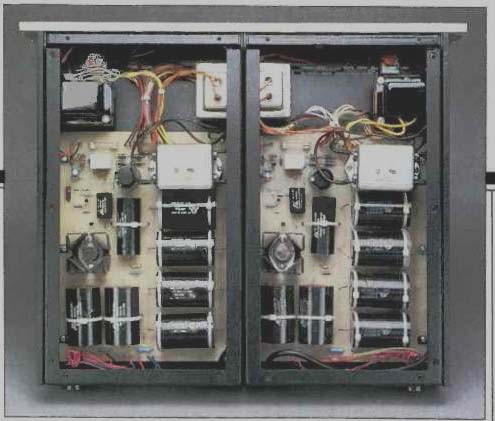
Like the preamp itself, the Premier Seven-A's power sup plies are separate mono units, in this case attached, side by side, to the front panel and to shared top and bottom covers that further strengthen the assembly. Each supply contains two power transformers, one for the tube heaters and the other for the high-voltage plate supply. A number of large film capacitors are used for the high-voltage filter capacitors. No electrolytics allowed here! However, in a concession to conventional practice, an electrolytic capacitor is allowed for the heater supply and time-delay circuit. A Sprague a.c. line filter and an a.c. line fuse are mounted on the p.c. board, as are a number of solid-state devices, including rectifier diodes, small transistors, and a high-voltage series pass transistor on a heat-sink.
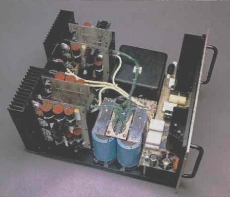
At the rear of the Evolution 2000 amp are four full-height, vertical p.c. boards that mount all the supporting parts for five MOS-FET output devices. These boards and the output devices mount to the heat-sinks. The space in front of the boards holds four 59,000-µF, 75-V filter capacitors for the main output stage and a very large potted power transformer for the solid-state output stage. Between them is a small power transformer for the tube front-end supply, topped by a p.c. board for the line-voltage selector. The remaining area behind the front panel is taken up by a p.c. board that mounts the front-end tubes and associated signal and power-supply circuitry. A high-current relay, mounted to the front panel near the tube window, turns on the power transformer in the output stage. The relay comes on with a very impressive "clunk."
Circuit Description
The Evolution 2000 amplifier has the simplest possible signal circuitry. The front-end uses all four elements of two dual triodes, paralleled in a common-cathode configuration and capacitor-coupled to the voltage gain of one solid-state output stage. There is no overall loop feedback, although some cathode feedback is used in the tube stage and local feedback is implicit in the output stage's cascaded voltage-follower topology.
The preceding would suggest that the amplifier is simple in a total sense; nothing could be further from the truth. For example, to elaborate on the output stage, the five pairs of MOS-FET output devices are driven by a pair of MOS-FET drivers, forming a Darlington-connected source-follower topology. While the supplies in the output stage are unregulated, the drains of the driver devices have their own supplies, each fed from a discrete complementary voltage regulator of appropriate polarity. This regulator design is used in virtually all conrad-johnson products. It consists of a current source feeding a zener-diode shunt regulator, which in turn feeds a Darlington-connected voltage follower that delivers the regulated output. These voltage regulators are fed unregulated positive and negative d.c. that is full-wave rectified and filtered from a separate winding on the power transformer of the output stage.
I could fill pages describing similar details. For example, the output drivers' gates are each fed from bias supplies that can be individually adjusted to control idling current in this stage and minimize d.c. offset in the output.
In the Premier Seven-A preamplifier, Messrs. Conrad and Johnson again use good-sounding amplifying devices. These devices have well-chosen operating points, are con figured in a common-cathode connection (common-emitter or common-source for bipolar and FET devices) with cathode feedback, and are usually followed by a similar device set up as a voltage follower. This type of gain block is always powered by conrad-johnson's usual solid-state voltage regulators.
In the phono preamp, the first stage is a pair of Nuvistor tubes in parallel, configured--you guessed it--in common-cathode mode but without the ensuing follower stage. The plate output of this stage is capacitor-coupled to a passive interstage RIAA equalizer terminating in a common-cathode second stage. This stage does have a cathode follower, which buffers the preceding tubes' plate circuit and drives the selector switches, volume attenuator, and tape out jacks when phono is selected. The polarity of the phono circuit is thus noninverting.
High-level inputs are fed into the "Source" and "Record" output selectors, which are wired in parallel. This arrangement leaves the possibility of a feedback loop (potentially destructive to ears, power amps, and speakers) via connected tape recorders or external processors when both selector switches are on the same "Tape 1" or "Tape 2" setting. Conrad-Johnson cautions against this in their owner's manual, but other preamps have dual selector-switch arrangements that prevent it altogether. Following the signal selector is the stepped attenuator, a multi-deck Stackpole unit that switches in resistor pairs for signal attenuation and also selects which front-panel "Attenuation" LED will light.
Switching in resistor pairs instead of picking off various taps along a string of resistors in series is a good idea, as it puts fewer resistors in the signal path for any attenuator setting.
The preamp's high-level line output amplifier is another gain block of the type described earlier. Its cathode follower provides a low output impedance to drive interconnect cables. The line output amplifier inverts polarity, so the preamp inverts all signals (which conrad-johnson spells out plainly in the manual)--but so does the Evolution 2000 amp, making a noninverting system if both are used together.
Each channel's separate power supply contains the high voltage plate supply (full-wave rectified, with film filter capacitors specially made for conrad-johnson) and the low-voltage supply for tube heaters and the time delays. The high-voltage regulators (a main regulator feeding sub-regulators for each signal block) are located on the preamp chassis. The heater supplies are also full-wave bridge rectified, filtered, and regulated in the usual conrad-johnson way. Ah, to be a tube heater in a conrad-johnson preamp I'd sound good too! There are two time-delay circuits in the power supply.
One delays B+ until the tube heaters are up to temperature (a nice touch that probably extends tube life and is seldom seen today). The other keeps both main and tape outputs muted (another rare, nice touch) until all the preamp's circuits have settled out.
Measurements
Starting with the measurements for the Evolution 2000, I found voltage gain into 8-ohm loads to be 30.5 and 30.4 dB, respectively, for left and right channels. Corresponding in put sensitivities for an output of 1 watt into 8 ohms were 84.5 and 85.0 mV.
Small-signal frequency response hardly varied as I changed from open-circuit to 8- and 4-ohm loads. In all cases, response was ruler-flat from 10 Hz to 10 kHz, with a slight hint of roll-off visible at 20 kHz and a 3-dB-down point at about 80 kHz. The closely matched results for each loading give some idea of the output regulation or output impedance (the more the measurements agree, the lower the output impedance). The Evolution 2000's behavior was very good here, in that the output impedance was fairly low and the frequency response was unaffected by the value of the resistive loading.
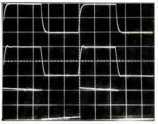
Fig. 1--Square-wave response, Evolution 2000 amp, for 10 kHz into 8 ohms
(top), 10 kHz into 8 ohms plus 2µF (middle), and 40 Hz into 8 ohms (bottom).
Scales: Vertical, 5 V/div.; horizontal, 20 µS/div. for 10 kHz, 5 mS/div.
for 40 Hz.
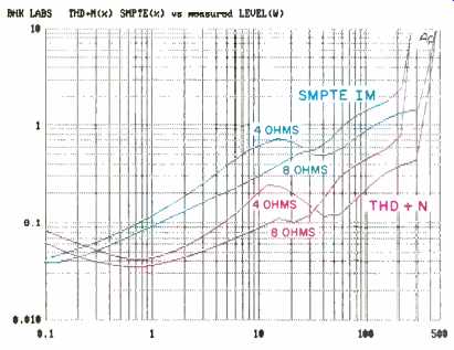
Fig. 2--Distortion vs. power output.
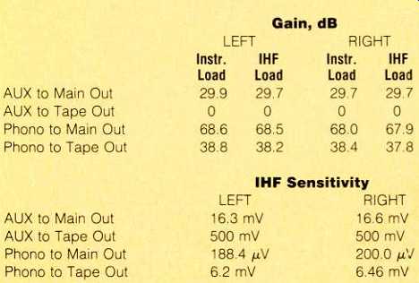
Table I--Gain and sensitivity, Premier Seven-A preamp
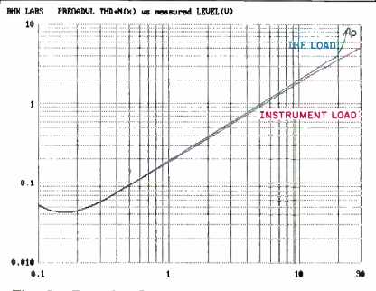
Fig. 3--Premier Seven-A line section THD + N vs. output level and load.
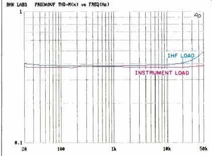
Fig. 4--Line section THD + N vs. frequency and load at 2 V out.
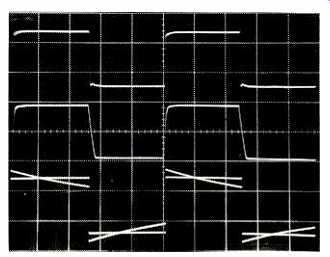
Fig.
5--Line section square-wave response for 20 kHz into instrument load (top),
20 kHz into IHF load (middle), and 20 Hz into both instrument and IHF loads
(bottom; traces superimposed). Scales: Vertical, 5 V/div.; horizontal, 10
µS/div. for 20 kHz, 10 mS/div. for 20 Hz.
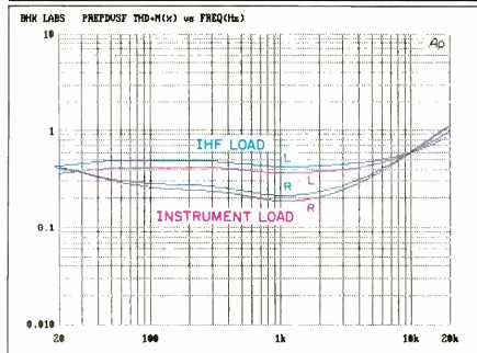
Fig. 6--Phono section THD + N vs. frequency and load at 2 V out.
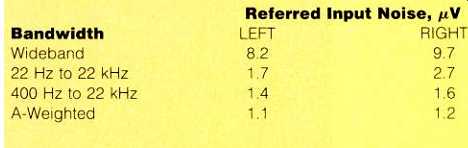
Table II--Output noise, referred to input, of Premier Seven-A line amp section,
with volume controls at maximum and input terminated by 1 kilohm. The IHF
S/N ratios were 85.1 dB for the left channel and 83.0 dB for the right channel,
for a 500-mV input and output and with volume controls at-29 dB.
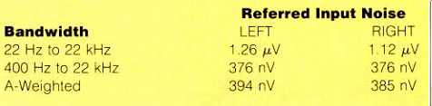
Table III--Phono section noise, referred to input, with 100-ohm input termination.
The IHF S/N ratios were 62.2 dB for the left channel and 62.4 dB for the
right channel.
Figure 1 illustrates the square-wave response of the Evolution 2000. The top trace is for 10 kHz into an 8-ohm load.
In the middle trace, a 2-µF capacitor has been paralleled across the 8-ohm load; the amount of ringing and change in shape of the waveform with the added 2 µF is exceptionally low. The bottom trace shows satisfactorily minimal low-frequency tilt with a 40-Hz signal. In view of the uniformity of frequency response, the rise- and fall-times, not surprisingly, do not vary with changes in the resistive load; they measured about 4.2 µS. Waveshape remains exponential (like the top trace) from small-signal up to high-power levels.
Figure 2 shows both THD + N and SMPTE-IM distortion for 4- and 8-ohm loading. The curves' characteristics are typical for tube amplifiers. The slight irregularities in the curves from 10 to 20 watts, especially with 4-ohm loading, may be associated with the onset of device cutoff as the circuit leaves the Class-A condition. Distortion stayed relatively unchanged as a function of frequency at any particular power output, for both 8- and 4-ohm loading, though at lower power levels it did rise a bit above 10 kHz. Harmonic distortion residue at the 10-watt level at 1 kHz was fairly low (0.09%) and uncomplicated with an 8-ohm load but was higher (0.18%) and more complex into 4 ohms.
Damping factor for 8-ohm loads was 30 at all frequencies from 10 Hz to 20 kHz. This uniformity is a testament to the amp's stability over the audio frequency range.
Measurements of dynamic clipping headroom yielded dynamic power levels of 233 and 420 watts, respectively, at the visual onset of clipping into 8- and 4-ohm loads. Since power is rated at 200 watts per channel into 8 ohms, the corresponding dynamic headroom is 0.66 dB. Steady-state clipping at visual onset of clipping occurred at 230 and 400 watts for 8- and 4-ohm loads, respectively. Clipping head room for 8-ohm loads worked out to 0.61 dB. It's notable how close the dynamic and steady-state clipping measurements are, a good indication of the excellent regulation of the output stage's power supply. Clipping at 20 kHz was perfect, with no "sticking" effects observed.
Noise was slightly higher in the right channel, which yielded an IHF S/N ratio of 87.5 dB versus the left channel's 89.7 dB. Output noise figures for the two channels were 450 and 240 µV wideband and 235 and 198 µV from 22 Hz to 22 kHz. The A-weighted figures were 120 and 93 µV for the right and left channels, respectively.
I suspected the input capacitance might be on the high side because the four paralleled tube elements' plate-to- grid capacitances would be multiplied by the Miller effect (i.e., by the stage gain). It measured 590 pF-not a problem when the input is driven by the normally low output impedance of a preamp, but it did cause some extra high-frequency roll-off (beyond that caused by my long interconnect cables) when I used my reference signal selector/switched attenuator unit. The a.c. line draw of the Evolution 2000 at idle was about 2.6 amperes.
Now we move on to the Premier Seven-A preamplifier, whose measured gain and input sensitivities are listed in Table I. The output line amplifier's frequency response, with volume controls set at maximum, was perfectly flat from about 10 Hz to 200 kHz with instrument loading. Notably, there was little change in response when driving the 10 kilohms and 1,000 pF of the IHF load-just a roll-off of a fraction of a dB from about 50 to 200 kHz and of about 1 dB at 10 Hz.
Further evidence of the Premier Seven-A's ability to drive an IHF load is shown in Figs. 3 and 4. Figure 3 is a plot of output voltage versus THD + N at 1 kHz, with instrument and IHF loading. The instrument load of about 100 kilohms is what most tube preamps like to drive. With the IHF load, note that the distortion is about the same up to 20 V. This baby can drive! Distortion is almost pure second harmonic over most of the range. Figure 4 is THD + N at 2 V output as a function of frequency and loading. Again we have substantially constant distortion over the audio range and relatively little change for the IHF load.
Rise- and fall-times at 2 V peak to peak and with volume at maximum were 350 nS with the instrument load and increased to about 650 nS with the IHF load. With volume turned down to the-6 dB setting, rise- and fall-times increased to 800 nS with the instrument load.
Square-wave response through the Premier Seven-A's line amplifier, with the volume controls at maximum, is illustrated in Fig. 5. The output level shown is about 10 V peak to peak. The top trace is for 20 kHz with an instrument load.
The edge transitions are very fast and a mild high-frequency compression (or shelf roll-off) is in evidence, as the steady state peak-to-peak amplitude is greater than the fast edge transitions. In the middle trace, you can see positive-going edge transitions being slowed down and some slewing in the negative direction, both due to the IHF load's 1,000-pF capacitance. However, the slewing only starts at about 4 V peak to peak-a signal level that would drive most power amplifiers into clipping. This is due to the single-ended cathode follower's inability to drive a capacitive load fast when the tube is being turned off. The effect of the IHF loading on square-wave tilt at low frequencies is depicted in the bottom, 20-Hz. trace of the figure. The amount of tilt with the instrument load is exemplary, and the amount with the IHF load is quite acceptable in view of the relatively low capacitance (4 uF) of the polystyrene output coupling capacitors.
Channel-to-channel tracking of the separate volume controls versus the panel's attenuation markings was quite good, off by less than 0.6 dB. The channel-to-channel differences were generally on the order of half this amount.
Noise levels of the output amplifier are enumerated in Table II. The noise is quite satisfactorily low. Output impedance of the line section measured about 175 ohms. Interchannel crosstalk was greater than 110 dB from 10 Hz to 50 kHz and consisted more of output amplifier noise than of crosstalk per se. Any other result would be suspect due to this preamp's dual mono nature.
The phono section's RIAA equalization was very good, varying by only about 0.1 dB over the audio range with instrument loading. The IHF load had little effect except for a small level drop, slightly more than 0.5 dB, and some low frequency roll-off (less than 0.5 dB at 20 Hz) caused by the preamp's output coupling capacitor combining with the 10 kilohm load to form an RC high-pass filter. The level drop was due to the attenuation of the 10-kilohm resistance of the IHF load against the phono stage's equivalent output impedance of some 700 ohms.
Phono overload, as represented by the 3% THD point, was attained for instrument loading at a 1-kHz input level of about 0.2 V and an output level of about 10 V; for IHF loading, the figures were about 160 mV and 8 V, respectively. These results are for the left channel; the right channel put out some 60% more. For either load, the behavior remained pretty constant at all frequencies to about 5 kHz, dropping gradually by about 2 V at 20 kHz with instrument loading and dropping a bit less with IHF loading. Since the distortion rise versus output level is rather gradual in this circuit, it is a little less precise to cite overload versus frequency at an admittedly arbitrary distortion level of 3% than it would be with the usual feedback circuits, which clip or distort more abruptly.
When I tested the phono section with 1-kHz, pre-equalized square waves, the two channels behaved more alike than in the sine-wave overload test. Performance here was pretty good, with about 1 V peak to peak attainable before asymmetry set in.
Total harmonic distortion versus frequency and load, at an output of 2 V for both channels, is plotted in Fig. 6. As mentioned earlier, the right channel has lower distortion.
Distortion at 1 kHz was generally about 0.1% or less at working levels, especially with moving-coil pickups. It increased gradually with output, to 2% or 3% at the 10-V level.
Input-equivalent noise levels, along with phono IHF S/N ratios, are listed in Table III. Relative to the output of a typical moving-magnet cartridge, the noise levels are quite satisfactory. Relative to typical moving-coil output levels, the noise is marginal and would likely be audible at high volume settings when the arm is off a record.
Phono interchannel crosstalk was measured. As with the line amplifier, it was better than 100 dB down and was dominated by random noise in the input stage.
Use and Listening Tests
My first listening tests were made with the Evolution 2000 amplifier powering the electrostatic panels of Martin-Logan Monolith speakers. A McIntosh 2600 solid-state amp was used to drive the woofers in this speaker system. I was immediately impressed with the musical honesty of the conrad-johnson amp. At the time, I was mainly using Carver Silver Seven tube power amplifiers in this service, with superb results. My feeling was that the c-j amp was very good, in many ways comparable to the Carvers' excellence.
I then tried the Evolution 2000 in full-range use with other speakers over a period of time. Again, I generally thought the results were very good, affording well-balanced tonality and a high degree of musical satisfaction.
For the preceding tests, I used a Quicksilver Audio tube preamp and a Vendetta Research phono preamp. Next, I put the conrad-johnson preamp into the system. I again set up the Monoliths with the Evolution 2000 driving their electrostatic panels. Now, here was good sound! I listened to this combination for weeks and got some of the best sound I had heard in my setup in some time. Tonal balance was very neutral, definition and space were very good, and the overall sound was quite musically engaging.
Finally, to get a point of reference, I hooked up the Carvers to drive the panels with the Premier Seven-A as the preamp and proceeded to listen. I still preferred the Silver Sevens overall but again came to the conclusion that the Evolution 2000 is one very fine power amplifier. I am very glad that I had the chance to experience it and the Premier Seven-A in my system. Judging by the overall results I got using the preamp, I think it is one of the best-sounding preamps I have had in my setup.
Both pieces of gear operated flawlessly, but I have one nit to pick about the volume controls on the preamp. Since the Evolution 2000 has relatively high gain and the line output amplifier of the Premier Seven-A also has higher than normal gain, my high-level sources required that the volume controls be set down near the bottom of their range for my normal listening levels. In some cases, even the minimum volume setting was louder than I wanted. When playing records without a step-up device, I had the volume controls up much higher in their range, where I could adjust them with greater resolution. Some hiss could be heard at normal levels when the arm was off the record, but it was not high enough to distract from the music.
To sum up, the sound that I got from either piece alone, and certainly from the combination, was quite musically satisfying. I enjoyed music with these conrad-johnson components a lot and strongly recommend that prospective buyers of equipment in this price range give the Evolution 2000 and Premier Seven-A an audition.
-Bascom H. King
( Audio magazine, Jun. 1992)
Also see:
Conrad Johnson PV-5 Preamp (Auricle; Aug. 1984)
Link | --Conrad Johnson Premier Five Amplifier (Aug. 1986)
Coda Technologies FET Preamplifier 01 and Amplifier System 100 (Mar. 1993)
David Berning EA-2101 Amp & TF-12 Preamp (Dec. 1991)
Counterpoint SA-220 Power Amp (Jul. 1990)
Cary Audio CAD-50 and CAD-505L Mono Amps (Jul. 1991)
= = = =