LIKE any other apparatus, recording systems develop difficulties and faults, and recordists run into snags. This Section lists a number of common troubles of the system and suggested solutions.
The Stylus SHARPNESS: If a stylus is sharp, the grooves will be shiny; if not, it will tear instead of engraving and polishing. If it is dull and if it is actually chipped, an audible hiss can usually be heard during cutting.
Have styli re-sharpened frequently.
LENGTH : Styli which are too long or short for the system after it has been adjusted will cause variations in the angle which the cutting face makes with the disc surface. This angle should be just 90 degrees.
Use only styli of the length used when adjustment was made.
SHANK : If the shank is too soft, as with steel styli, high frequencies will be attenuated due to stylus compliance. Stellite and sapphire styli are invariably mounted in sufficiently stiff shanks.
The Cutter OVERLOADS: Distortion not present in the amplifier or sound source may be traced to cutter overload. Do not exceed the manufacturer-recommended applied voltage and/or power. Above this limit, cutter response is nonlinear, that is, an increase of level applied will not cause a corresponding increase of stylus movement. To make certain cutter is operating linearly, feed amplifier an oscillator tone which is varied in level in 2-db steps. Playback on a linear phonograph should show an output increasing in steps of the same amount. If increase becomes smaller as level reaches the maximum, cutter is being overloaded at the point where the increase begins to vary. Since surface noise is not an important factor with instantaneous discs, it is best to lean over back ward in staying under the maximum allowable level to be fed the cutter..
If pre-emphasis of any frequencies is employed prior to the cutter, measure maximum level at the most pre-emphasized frequency.
CONNECTION : Feed magnetic cutters from a source of the same impedance at which the maker rates the cutter. Experiment with the connection of crystal cutters as suggested in Section 11. Mistakes in connection may cause distortion.
AVAILABLE DRIVING POWER : If distortion occurs On peaks, it may be caused by an amplifier with insufficient power to supply the peaks without excessive distortion. Use an amplifier capable of supplying 3 times the normally required power, at 2% or less harmonic distortion.
If amplifier is too small, reduce output and cut at lower average level.
The Feed Mechanism
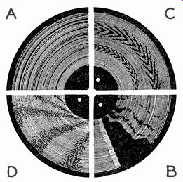
Fig. 1401--Four common types of faulty disc pattern, each caused by
some specific recording defect de scribed in text: a-Improper groove
spacing; b-Recording on a warped disc; c, d-Hum or turntable rumble.
GROOVE SPACING: A pattern somewhat like Fig. 1401-a indicates that the lead screw is not spacing the grooves accurately. The screw may be worn so that some of the threads are chipped off or the threads may be fouled with chip or dust and dirt. They may be insufficiently lubricated. The guide trolley may be too dry to allow the cutter mount to travel freely ; causing the mount to rise and take the half-nut out of the screw threads. The half-nut may not be solidly in the threads ; there is often an adjustment for this.
The Disc
SURFACE BRIGHTNESS: A well-cut disc will appear shiny under a single light source. If it is not, probably the stylus is bad. Or it may be that the disc coating has dried out from age, or, with off-brand discs, the coating may be inferior to begin with. Dullness will mean surface noise in playback.
WARPING: Discs which are warped before cutting will cause the stylus to jump up, causing a pattern like that of Fig. 1401-b. It is usually impossible to flatten warped records, and they should be discarded. This is actually good economy, since a jumping stylus will come down too hard and will eventually, if not immediately, become a broken stylus. Good styli, as you will discover, are much more expensive than good discs !
CUTTING DEPTH: If cutter weight is too great, the stylus will cut too deep. If stylus hits base material, it will be chipped. Even if it is not, groove width may become so great that the stylus will cut into adjacent grooves on high-level passages. If depth of cut is too small, play back pickups will not track, but will jump out of the groove and skid.
Chips should be about the texture of a very coarse human hair and should come out in one piece, not crumbled.
The Turntable SPEED: Speed should always be measured while a cut is being made.
On rim-drive tables, a small adjustment of idler pressure will often correct small speed discrepancies. If the speed is uneven, the motor may be too small or the idlers may be flatted. Chip may also tangle in either the drive mechanism or the motor and cause binding. If the overhead lathe does not exactly fit the table, it can cause speed variation. Bearings may also be fouled with chip. Lubrication of the entire mechanical system may be insufficient. Warped or unevenly coated discs can cause wows.
VIBRATION: Turntable rumble will record a hum on all discs cut with it present. This will cause an optical pattern which resembles Fig. 1401-c or d. (This pattern is also caused by amplifier hum.) Try isolating the motor from the case and mounting with shock mounts or putting the screws through live-rubber grommets. See that the case is solid, with no loose wooden parts. Often rumble can be minimized by fastening the motor and table very tightly to the case. This problem is prevalent with the less expensive motors ; but even with the best ones, the shock mounts supplied may be dried out, in which case they should be replaced. Be sure that the assembly is gravitationally centered.
Flatted idlers are a cause of rumble, as are uneven or worn drive shafts and bearings. The motor armature may not be properly centered. Idler pressure against turntable may be too great.
The Amplifier HUM: See that filament leads are twisted and kept as far as possible from audio leads, especially in early stages. Mount power transformers as far from low-level, a.f. stages as possible, and orient for least hum before screwing to chassis. Orient interstage and input transformers also. See that filter condensers are of high quality and in good condition. The entire power supply filter must be very effective. If system is in 2 or more parts, see that all chassis, motor frames, cabinets, etc., are bonded together and grounded with very heavy wire or shield braiding. While an actual ground may not be necessary, bonding definitely is.
However, grounding is good for draining static charges, especially on the disc. See that high-impedance input leads are shielded and the shield securely grounded to the system. Do not overdo the shielding within the amplifier, as this will reduce high-frequency response. Check for bad potentiometers whose arms do not make positive contact with the resistance strip.
RANDOM NOISE: This can be caused by excessive gain making audible the tube hiss caused by shot effect. Loose connections or cold solder jobs are a prime cause. Check all plugs and terminals. Bad interstage blocking condensers and plate load resistors are often guilty. If nothing else works, prod the wiring gently with the insulated handle of a screw driver until the noise is localized. See that all components are rigidly mounted. Small resistors and condensers can be mounted by their leads if the leads are not too long, but never wire 2 of them in series and support them by 1 lead of each. Make generous use of small tie lugs, brackets, and mounting strips. If all else fails, remove all ground connections from the chassis and run a heavy bus bar through the amplifier, tying all grounds to it. Grounds for each stage should be very close to the same point. Check microphones, pickups, and tuners to see that they are noiseless.
MICROPHONICS: If sound is heard when a tube is lightly tapped, the tube must be shock-mounted. (Occasionally a particular tube may be microphonic because of a manufacturing defect. Replace it.) Fasten the socket to the chassis through 2 rubber grommets. Pentodes are more susceptible to microphonics than triodes, as well as being more subject to hum and shot effect. However, non-microphonic pentodes, such as the 6S J7-Y, are often available. 6J7's are less noisy and cause less hum than 6S J7's.
HIGH-FREQUENCY DROPOFF: High-impedance circuits are most susceptible, especially plate circuits of pentodes and all grid circuits. Keep wiring of these parts away from chassis and as far as possible from each other. Use no more shielded wire in the amplifier than the minimum which will eliminate hum. Use high-quality transformers correctly connected. Check to see that no shielded leads longer than about 15 feet are run to the amplifier from microphones, pickups, and tuners which have high-impedance output. If longer lines must be run, use low-impedance devices and line-to-grid input transformers. Do not try to correct by using equalizers except as a very last resort.
LOW-FREQUENCY DROPOFF: Use large interstage blocking condensers--0.1 uF being about right for any stage. See that interstage and output transformers are not carrying any more d.c. than ratings allow. Where possible, it is desirable to use transformers rated at zero d.c., with shunt-fed plate circuits. See that cathode bypass condensers are large and in good shape. Where the cathode resistor is 2,500 ohms or more, 25 µf should be used ; larger capacitance where the cathode resistance is smaller. To be exact, condenser's reactance (Xe) should always be 0.1 R or less at the lowest desired frequency.
POSITIVE FEEDBACK: If the amplifier develops oscillations, it is probable that some stage is feeding back to another stage in phase. Be sure that inputs and outputs are well separated. Capacitance between in put and output leads will decrease to below the danger point if this pre caution is taken. Use decoupling filters on at least every other stage to prevent low-frequency motorboating oscillation.
NEGATIVE FEEDBACK: Negative or inverse feedback is used to increase range and reduce distortion. Be sure the feedback components do not introduce frequency discrimination. Unintentional inverse feedback may occur when the output of one stage is fed back to the input of an earlier stage through capacitance between closely spaced wires. Since the feedback is capacitive, it will increase with increasing frequency and the highs will feed back most, causing an over-all reduction of high response. Whether this unintentional capacitive coupling will cause high-frequency reduction or oscillation depends entirely on whether it is in or out of phase; in other words, on which stage feeds back to which stage. However, since unintentional coupling is undesirable in any case, eliminate it by isolating leads as far as possible. Don't try to cram a big amplifier into a small space. Recording systems are not ideal pocket-size gadgets!
General CHIP: The chip must not be allowed to entangle with the stylus.
Use a hand brush and plenty of personal attention, or an automatic brush such as that shown in Fig. 409, Section 4. If it does tangle, extricate it with the utmost care. If the stylus jumps over the chip, the disc will be damaged.
PLAYBACK: Use only the lightweight pickups and the best shadow-graphed steel or built-in permanent needles to play records back. Frequency-response faults may be corrected by the methods presented in Section 13.
STORAGE: Store discs on edge in a press. Keeping them on a shelf beside or between a number of other discs, all fairly tightly packed is ideal for prevention of warping. Keep away from excessive heat. Store in record envelopes, as dust is the cause of much noise in playback. If discs become too dusty, wash in almost cold water (no soap) and dry either with a lintless silk cloth or leave exposed in a dustless room. If water is hard, it is better to dry the disc with a lintless cloth.