| Home | Audio mag. | Stereo Review mag. | High Fidelity mag. | AE/AA mag. |
In the last ten to fifteen years [ca 1960], remarkable progress has been
made in the field of sound recording and reproduction. The introduction
of high-fidelity disc and tape recordings and the improvement in the design
of playback equipment have set new standards for the discerning listener
and have consequently created the need for systems providing amplification
of the highest quality. Because of the variety of signal sources in existence,
the range of application of these systems has had to be wide. Therefore,
pre-amplifying circuits which cater for pick-up and tape playback heads,
FM tuner units and microphones have assumed great importance. Furthermore,
the emergence of stereophonic recordings and pick-up heads has created
a demand for dual-channel amplification and this has been fulfilled in
equipment consisting of either self-contained stereophonic amplifiers or
specially-designed stereophonic pre-amplifiers coupled to pairs of conventional
power amplifiers. This guide contains descriptions and details of high
quality amplifying and pre-amplifying circuits for monaural and stereophonic
applications which can be classified as shown in Table 1. Most of these
circuits have been designed to be used with each other, and examples of
various arrangements of the items of equipment are discussed in subsequent
paragraphs of this section.
MONAURAL SYSTEMS
The choice of line-up is dictated to a large extent by the strength of the signal to be reproduced. For example, the version of the 10W circuit incorporating volume and tone controls can be used satisfactorily without a pre-amplifier if input signals greater than 500mV are available. (Such signals can be obtained from high-output crystal pick-up heads or FM radio tuner units.*) The 3W circuit with volume and tone controls can be used directly with sources which give signal voltages greater than 100mV.
However, signal voltages from low-output crystal pick-ups, magnetic pick-ups and tape-recording heads (which can have values of up to 500mV but are usually between about 2 and 100mV) are normally too low for direct use with the power amplifiers, and a preamplifier is necessary to increase the sensitivity of the system. In addition, discs and tapes are deliberately recorded in such a manner that the strength of signals derived from them will be a function of frequency (see Section 2). Consequently, the strength of these input signals will usually vary in some way not related to the original sound patterns and, to obtain realism from such recordings, some degree of compensation is required in reproducing these sounds. This equalization is best incorporated in a pre-amplifier, so that the scope of application of power amplifiers can be increased without any resultant fall in the standard of performance. The 2- and 3-valve (tube) pre-amplifier circuits described in Section 9 have been designed to precede either the 3W, 10W or 20W amplifier.
• The circuits described in this guide can be used with the better quality FM tuner units available commercially. No tuner unit is described here because it is felt that the inherent difficulties of alignment cannot be overcome with the test equipment currently available to the home constructor.
The simple arrangement for the 10W and 3W amplifiers connected directly to the input source is shown in Fig. 1. The use of pre-amplifiers is indicated in Fig. 2.
------------------
TABLE 1 Classification of Mullard Circuits
Power Amplifiers of General Application Five-valve (tube) , twenty-watt circuit (‘5-20'); Five-valve (tube) , ten-watt circuit * (‘5-10'); Three-valve (tube) , three-watt circuit * (‘3-3').
Pre-amplifiers of General Application Three-valve (tube) circuit; Two-valve (tube) circuit; Input-mixing circuit.
Power Amplifiers of Special Application Seven-watt, d.c./a.c. circuit; Three-watt tape circuit (Type A revised); Seven-watt stereophonic circuit; Two-watt stereophonic circuit.
Pre-amplifiers of Special Application Tape-equalizing circuit (Type C revised); Twin-channel stereophonic circuit.
* Two versions: one with, one without tone and volume controls.
-----------------------
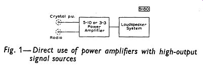
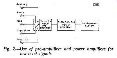
Fig 1; Fig 2
The 3 W tape circuit comprises a self-contained record-playback system for microphone and radio input sources. The circuit is also suitable for replaying pre-recorded tapes. A program-monitoring signal is available when recording and, during playback, this source will provide a low-level signal suitable for driving a power amplifier if an output power higher than 3 W is required.
STEREOPHONIC SYSTEMS
For stereophonic reproduction, two separate amplifying channels are required, one for each of the twin signals obtained from the stereophonic signal source. In the simplest arrangement, the 2W or 7W stereophonic amplifier is connected to the source as shown in Fig. 6. If the stereophonic pre-amplifier is used, it should be coupled to two power amplifiers and loudspeaker systems as in Fig. 7.
The tape pre-amplifier provides recording facilities comparable with the self-contained unit but, on playback, the circuit only provides an equalized signal for driving a power amplifier. A simple arrangement for the combination of tape pre-amplifier and power amplifier is shown in Fig. 3. This line-up is suitable also for the 3W tape amplifier when the low-level playback output is used.
For a complete record/monitor-playback system using pick-up input sources, the tape pre-amplifier should be used in conjunction with the line-up of Fig. 2. The new arrangement is shown in Fig. 4*. When recording, the input signal is fed to the appropriate input channel of the pre-amplifier and then from the program-recording output of the pre-amplifier to the input of the tape circuit. The program can be monitored by using the normal output of the preamplifier to drive the power amplifier. For playback, the equalized output from the tape pre-amplifier is fed via the Auxiliary input channel to the main amplifying chain.
Stereophonic systems should be suitable for reproduction from monaural sources, and ‘compatibility' switches are usually incorporated for this purpose. For instance, the switching indicated in the preamplifier stage of Fig. 7 selects the input channels* and also sets the equipment for normal or reversed stereophonic reproduction or for monaural reproduction using both power amplifiers and loudspeaker systems.
* It is important that the tape deck in both these arrangements should always be switched to the playback position before the connection from the tape output to the pre-amplifier input is made. 1f the tape recorder is in the record position when the connection is made, oscillation will occur.
To feed several inputs into an amplifying system at the same time, the main pre-amplifier in Fig. 2 should be replaced by the input-mixing pre-amplifier. Recording, monitoring and playback are possible with the new arrangement shown in Fig. 5.* The output impedance of the mixer is low so that the inputs of the tape pre-amplifier, and the power amplifier can be connected simultaneously to the mixer without affecting the quality of reproduction.
* Facilities are provided for stereophonic radio signals in anticipation of stereophonic transmissions.
POWER SUPPLIES
Facilities are provided in the 10W and 20W amplifier circuits for obtaining power supplies for a single-channel pre-amplifier or FM radio tuner unit. For stereophonic applications, the h.t. supply for each channel of the pre-amplifier can be taken from the power amplifier used with 'that channel.
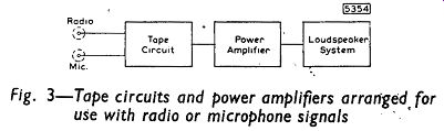
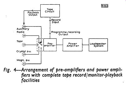
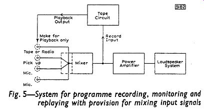
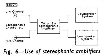
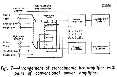
Fig 3- Fig. 7
The h.t. supply facilities for pre-amplifiers are also available in the 3W circuit. Those for FM tuner units are not immediately so, but the modifications required are not extensive. The current drain when an FM tuner is coupled to the amplifier is increased considerably and it will be necessary to choose a rectifier and mains transformer which will supply this current. Extra stages of decoupling will be required to prevent excessive hum voltage being picked up in the sensitive early stages of the tuner.
A separate power stage is described for the tape pre-amplifier, and this can be retained when the preamplifier is used with any of the power amplifiers. Physically, however, the extra unit may prove an encumbrance and consequently it may be preferable to use the supply stage of the main amplifier to provide the needs of the tape pre-amplifier.
NOTE: The word monaural is at present commonly used to depict conventional 'sound reproduction in which a single-track recording and a single pick-up head (or tape playback head) are used. The word monophonic may often be encountered as a synonym of monaural and may eventually supersede it. Monaural means, literally, of one ear and a monaural effect is that of listening with one ear, when no impressions of space or displacement are conveyed to the listener. Monophonic means of one sound source so that monophonic reproductions again lack any impressions of spread or position. Monaural has been adopted in this guide simply because it is currently more popular: its use should not be taken to imply any etymological superiority of the word over monophonic.