| Home | Audio mag. | Stereo Review mag. | High Fidelity mag. | AE/AA mag. |
Some distortion is always present in the sound reproduced from a gramophone
record or magnetic tape. It is inevitable that part of this distortion will
be distortion recorded on the disc or tape itself, but the loudspeaker, pick-up
and recording head also make substantial contributions. A carefully constructed
amplifier is far from being the weakest link in the chain: in fact, it is
improbable that the limit to the quality of reproduction which can be obtained
will be set by the performance of the amplifier. High-quality reproduction
will only be achieved if careful attention is also paid to the sound input
source and to the loudspeaker.
Even if perfect associated equipment could be obtained, however, it would not be possible to eliminate distortion entirely. There would still be some distortion - a comparatively small amount it is true which is bound to occur when discs or tape are used. The function of this section is to give brief accounts of the main items of associated equipment needed for disc or tape reproduction and also to discuss some of the causes of distortion, indicating the methods by which imperfections are minimized.
LOUDSPEAKERS
The choice of a suitable loudspeaker is very important for both disc and tape reproduction. While it would be wrong to assume that price is the only guide available, normally -the higher grades of loudspeaker will justify their extra cost by giving correspondingly better reproduction. The choice should never be made hastily. It is not sufficient to listen; to one or two records because it is very easy to construct a system which will sound impressive at first hearing.
Extended periods of listening to music are desirable to discover if mental fatigue is likely to be caused by the system. Furthermore, because it is easier to judge speaker quality by listening to comparatively simple sounds rather than to full orchestral recordings, the system should also be tested by assessing the fidelity with which good-quality broadcast speech is reproduced.
A simple, direct-radiator loudspeaker -- that is, a single-cone unit handling the entire range of frequencies--can give excellent results when mounted in a suitable enclosure. It is important to remember that this enclosure should always be that specified by the speaker manufacturer since it is not possible to design a suitable cabinet without knowing accurately the basic performance of the loudspeaker unit. One of the main disadvantages of all types of simple direct radiator is that the high-frequency response is very directional. This fact, however, can to some extent be overcome by using the loudspeaker in conjunction with some form of reflector. The reflector can be built into the cabinet, or the corner of a room can be used for the purpose. The effect of the reflector is to distribute the high-frequency components in a more random manner so that, with the adequate treble boost provided by the amplifier, good results will be obtained.
There is no doubt, however, that even the simplest of dual systems is much better than a single unit. Such a dual system may consist of two direct radiators- for example, a 12 in, unit for the bass-end of the spectrum and a 5 in. unit for the middle and treble components- used in conjunction with a suitably designed cross-over network. It must be remembered that, while the effective frequency response may not be very much increased by this type of dual system, various forms of distortion will be reduced considerably, added to which there will be a better distribution of high frequencies from the smaller source.
Dual systems using twin direct radiators are available in two forms: either with two completely separate units, each mounted in its own enclosure or, alternatively, with the high-frequency unit mounted on some form of modified frame, making it an integral part of the low-frequency unit.
Greater improvement may be obtained by using three loudspeaker units together with a three-way cross-over network. This extends the frequency range and reduces the distortion still further, as well as providing a wider range of distribution patterns.
Normally, suitable cross-over networks are recommended by the loudspeaker manufacturers, and it is usually best to adopt these recommendations. However, an example of a two-way network having a very compact design and unusually low losses is shown in Fig. 1. Two Mullard Ferroxcube pot-core inductors, type LA23, are used in conjunction with the special metallized-paper capacitors now available, and a maximum rate of attenuation of 12dB per octave can be obtained from the constant-resistance circuit.
The values of L and C in the diagram are given in terms of the loudspeaker impedance R and the crossover frequency f by the following equations:
L = Rv2
2?f
C = v2
4?fR
The approximate number of turns required on the inductor for a given inductance L is 53vL, where L is in millihenries.
In practice, the impedance R of the speaker will already be determined, and it will be convenient to obtain the value of capacitance to give the required cross-over frequency from the appropriate section of Table 1. The corresponding value of inductance, and the approximate number of turns to give this value, can then also be obtained from the table.
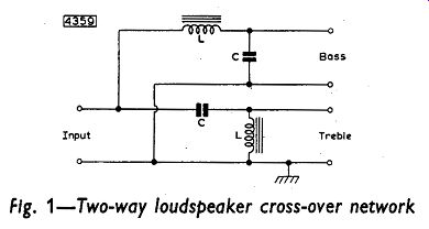
Fig 1
One advantage of horn-loaded loudspeakers over direct-radiator types is that the effective damping is increased, and, consequently, there is improved reproduction of transients. Some units incorporate a combination of a direct-radiator bass speaker and a horn-loaded treble speaker. They enable a higher conversion efficiency to be obtained in the treble region of the spectrum, thus ensuring a more even distribution for a given frequency response. In other words, the total energy output of the high-frequency unit is maintained up to a higher point in the musical scale. Although it is possible to use a completely separate horn-loaded tweeter, at least two manufacturers use a double-magnet system which permits the treble unit to be mounted concentrically with the bass unit. Thus, phase distortion at the cross-over frequency, which is produced in other systems by the distance between the two units, is also avoided. Also, the overall frequency response can be made smoother with the concentric system.
The most complicated form of dual loudspeaker system is that which is horn-loaded over its entire range. This may be achieved by using separate horn assemblies, each associated with a loudspeaker unit covering part of the frequency spectrum. Alternatively, loudspeakers of the concentric type can be used. Such systems are always expensive but they have certain advantages: the electro-acoustic conversion efficiency is high, the acoustic damping for the entire audio range is much improved over that of any simple direct-radiator system, and the larger size of bass horn gives better realism.
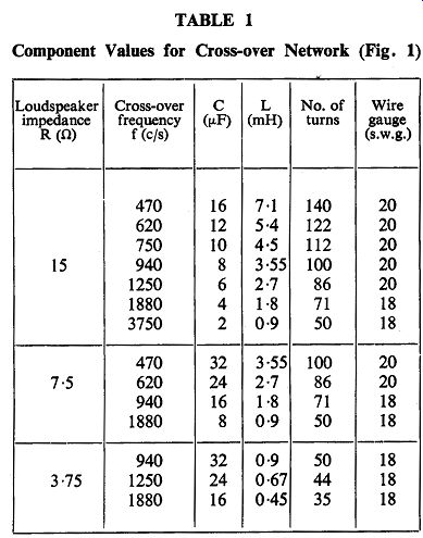
Table 1
DISC EQUIPMENT
RECORDING CHARACTERISTICS
Cutting Styli
When recordings are made on discs, the recording head is used to convert the signal voltage (or voltages, in stereophony) from the recording amplifier into vibrations of the cutting stylus. The stylus cuts the groove in the disc during recording, and the vibrations are reproduced in this groove as program modulation. With monaural recordings, the single program modulation appears as an identical* trace in both walls of the groove. With stereophonic recordings, however, the twin signals give rise to a more complex trace in which each wall of the groove carries one signal.
The cutting edge of a monaural stylus is rectangular and it cuts with a lateral movement so that the width of the recording groove is constant*. A stereophonic cutting stylus is triangular and has two cutting edges which are set symmetrically about the vertical at right-angles to each other. Each signal causes a cutting edge to move in a direction perpendicular to its length, so that the resultant movement of the stylus is not a simple one from side to side as with a monaural stylus, but is two-dimensional in the plane of cutting edges.
Thus, whereas a monaural stylus needs only freedom of lateral movement, a stereophonic stylus must have vertical compliance as well.
Characteristics
Except for the duality of stereophonic discs, the characteristics of monaural and stereophonic recordings are fundamentally the same.
Therefore, it is sufficient in these simple comments on recording characteristics to refer only to monaural recordings. The remarks can be applied, with suitable allowance for their two-fold properties, to stereophonic discs.
Magnetic recording heads are normally used for cutting discs: the stylus is attached either to the moving iron armature or to the moving coil. The velocity at which the stylus vibrates (measured as the stylus passes its equilibrium position) is directly proportional to the recording-signal strength, so that, for a constant voltage, the velocity is constant, and the amplitude or width of the groove is inversely proportional to the signal frequency. This is known as ‘constant-velocity' recording.
If the amplitude at high frequencies is chosen to give an acceptable signal-to-noise ratio, the amplitude at low frequencies will be excessive. Distortion will be high and too much space will be needed between adjacent rings of the groove to ensure that breakthrough from one ring to another does not occur. Thus, some restriction of the amplitude is desirable at these low frequencies and, to achieve this, bass signal voltages from the recording amplifier are attenuated before being recorded. Recordings in which the maximum width of the groove is restricted to some limit are known as ‘constant-amplitude' recordings.
Because of the difficulty in maintaining a satisfactory signal-to-noise ratio if a constant-velocity characteristic is used at high frequencies, it is normal to boost treble signals from the recording amplifier before recording them. Consequently, a recording characteristic indicating the variation of recording voltage with frequency can be divided into three sections: the bass section, showing voltage attenuation; the middle section, showing constant-velocity recording; the treble section, showing voltage boost.
An imaginary recording characteristic is drawn in Fig. 2. The frequencies at which the characteristic changes from one section to another are called the ‘turnover' frequencies. The slope of the bass and treble sections of the characteristic depends on the degree of attenuation or boost applied to the recording signal. If recordings with a constant amplitude of modulation are required, the stylus velocity must be proportional to the frequency and hence the signal voltage must also be proportional to the frequency. Thus, the signal voltage must be halved or doubled as the frequency is halved or doubled and this gives a characteristic slope of 6dB per octave.
Actual recording characteristics differ considerably from the imaginary one of Fig. 2. The straight lines of the characteristic cannot be achieved in practice, and actual characteristics are more like the continuous curve shown in Fig. 2.
The bass and treble turnover frequencies in actual curves are defined as those frequencies at which the ratios of the recorded voltages to the true signal voltage are 1:v2 and v2:1 (that is, - 3dB and + 3dB) respectively. The true signal voltage is assumed, for reference purposes, to be the level of voltage recorded at 1KHz.
In most practical characteristics, the middle horizontal section is discarded and only a point of inflection at 1KHz retained. The bass and treble sections of practical curves are not produced indefinitely with a constant slope, but are flattened at the limits of the range of audible frequencies.
PLAYBACK CHARACTERISTICS
If a magnetic pick-up head is used to reproduce the sound recorded on discs, the output voltage from the head will be proportional to the velocity of vibration of the needle. Consequently, the output from a magnetic head used with recordings made to characteristics of the type shown in Fig. 2 will increase with frequency in the bass and treble regions. (This will not be so with crystal pick-up heads as the output of these is proportional to the amplitude of modulation.) Thus, correction or ‘equalization' will be required during playback amplification to restore the true level of the signal voltage, and this equalization should be the converse of the attenuation and boost applied while recording.
The recording characteristics used by the different recording companies before 1955 followed, to a greater or lesser extent, the curve shown in Fig. 2, but the differences were large enough to make equalization a matter depending greatly on the records to be played.
Many companies issued their own equalization characteristics, and corrective networks had to be designed with these in mind. Examples of the playback characteristics of the major recording companies are shown in Fig. 3. In 1955, however, the majority of these companies agreed to adopt the characteristics of the Recording Industries' Association of America (RIAA), which are drawn in Fig. 4.
Consequently, there is no need, with up-to-date recordings, to adapt the pick-up head and record to each other by using separate equalizing networks for each brand of record. Instead, one network (usually in the form of a frequency-selective feedback network) can be incorporated in the amplifier. Of course, with the two characteristics for standard and microgroove records, separate networks will still be required for these.
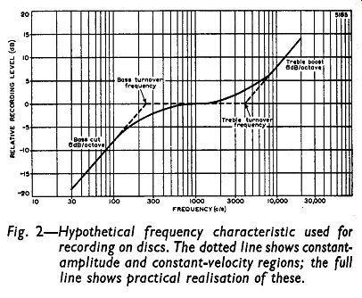
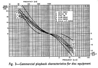
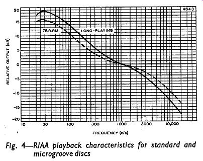
Fig. 2 - 4
PICK-UP HEADS
The principle on which a gramophone pick-up head operates can be one of several, but the commonest types of component belong to either the constant-velocity or the constant-amplitude group.
Magnetic pick-up heads (moving-iron and moving-coil) have basically constant-velocity characteristics, the output voltage being proportional to the velocity of vibration of the pick-up stylus.
Piezo-electric (crystal) heads possess constant-amplitude characteristics, the output from these varying with the amplitude of modulation in the recording groove.
As the RIAA recording characteristics (and, similarly, most of the commercial characteristics before 1955) do not possess purely constant-velocity or constant-amplitude properties, some degree of equalization will be needed with either group of pickup head, and the degree will be different for each group. However, simple resistance-loading of lower medium-output crystal heads will convert their characteristics into very near approximations of constant-velocity characteristics without prejudicing the standards demanded of high-quality equipment. Consequently, this method of loading is often adopted in high-quality amplifiers to give a simpler switching arrangement of the equalizing feedback networks. With it, the networks provided for standard and microgroove records using magnetic heads can also be used for medium- or low-output crystal heads.
Magnetic Pick-up Heads
Both types of magnetic pick-up head -that is, moving-iron and moving-coil - work on the principle of the dynamo: the change in magnetic flux through a conductor generates a voltage across the conductor. The change of flux in the heads results from the movement of either the magnetic core or the conducting coil, and this movement is caused by the vibration of the stylus (attached to either the core or the coil) in the recording groove.
The output voltage from either type of head is proportional to the rate of change of flux through the conductor and thus to the velocity of the stylus (measured at its equilibrium position). Output voltages which are quoted for comparing magnetic pick-up heads should therefore be given with reference to the stylus velocity. This reference can be made directly by quoting the velocity; alternatively the ratio (expressed in decibels) of the actual output voltage to that which would be obtained at some standard velocity (1cm/sec) should be given. Hence, an output voltage could be given as, say, 100mV at 3.16 cm/sec or 100mV at +10dB, and both expressions would be equivalent.
Moving-iron magnetic pick-up heads can be divided into three classes, governed by their outputs (measured at a stylus velocity of 3.16 cm/sec):
Low-output heads: Voltages below 20mV Medium-output heads: Voltages between 20 and 100mV High-output heads: Voltages above 100mV.
The basic output of a moving-coil pick-up head is of the order of millivolts. The lower level of output results from the desirability of lightness of the pick-up unit and hence the restriction on the number of turns of the coil.
Both types of head are suitable for high-quality equipment, although the intrinsically low output of the moving-coil type necessitates the use of a high-ratio pick-up transformer between it and the amplifier.
The impedance of magnetic heads is of the order of kilohms at signal frequency of 1KHz, and the required loading (that is, the input impedance of the amplifier) for the rated output of the heads is of the order of 100 ohm. Their loading should be independent of frequency, otherwise the input signal to the amplifier will also vary with frequency.
Crystal Pick-up Heads
A voltage is developed between the faces of a piezoelectric crystal when the crystal is strained. The voltage is proportional to the strain.
In a crystal pick-up head, the playback stylus is attached rigidly to some piezo-electric material, and a strain is produced in the material by the vibration of the stylus as it follows the modulation of the recording groove. The amplitude of this modulation governs the output voltage of the head.
The rated output voltage of a crystal pick-up head is always quoted at a particular frequency. This is essential because, for comparison purposes, a recording made to a constant-velocity characteristic is used and the amplitude of modulation - and, therefore, the output voltage - of such a recording is inversely proportional to the frequency. A typical output voltage from a high-output crystal head would be about 1V at 1KHz. The output at a frequency of 300Hz would therefore be about 3V. It is thus evident that attenuation is desirable at the lower frequencies to provide a balanced output and to prevent the input valve (tube) from being over-driven. The highest-quality crystal heads have outputs considerably lower than this, a typical value being about 0-5V at 1KHz.
The impedance of crystal pick-up heads is equivalent to a capacitance, the value of which is of the order of 1000pF. The optimum load resistance of a crystal head will depend on the method of loading. If it is loaded so that its characteristic is similar to that of a magnetic pick-up head, the load resistance is of the order of 100k-o. If the characteristic is not modified, then an input impedance of the order of megohms is desirable.
Stereophonic Pick-up Heads
Pick-up heads for use with stereophonic equipment can be of either the magnetic (moving-iron) or the crystal type. The construction of these pick-up heads, however, will differ considerably from that of monaural heads. They must be capable of responding to the two-dimensional modulation of the recording groove and of translating the response into two separate signals, whereas monaural heads have only to follow a lateral displacement and convert it into a single signal. Consequently, there must be two signal generators in each stereophonic head and these must have very similar characteristics. They will therefore both be of the same type - both crystal or both magnetic. Also, the pick-up stylus will require a vertical compliance comparable with its lateral compliance so that the tip of the stylus can follow the contours of the recording groove faithfully and provide balanced stimuli for the twin generators.
The output voltages obtained from these generators are very much lower than the voltages derived from monaural heads of the same type. Moving-iron, stereophonic heads will produce voltages of the order of millivolts for each signal, and crystal heads will give signals of the order of 100mV. The impedance of each section of a stereophonic head will be of the same order as that of the same type of monaural heads-about 1 kilohm for magnetic heads and the equivalent of about 1000pF for crystal heads.
DISCS
Records are normally made for replaying at three different speeds: 78, 45 or 33.333 RPM. The first or ‘standard' type of disc is pressed in a hard non-pliable material called shellac. Record wear with this material is relatively high even under good playing conditions. Wear with vinyl, the pliable material used for the 45 and 33.33 RPM, 'microgroove' type of disc, is very slight under comparable conditions. The main trouble with vinyl records is the tendency to collect dust through electrostatic attraction.
Standard records are made with diameters of 10 or 12 inches and provide playing times of about 4 or 5 minutes. ‘Extended-play' or 45 RPM discs have diameters of 7 inches and playing times of about 10 minutes. ‘Long-playing' or 33.33 RPM records are made with diameters of 10 and 12 inches and play for up to about 30 minutes.
Stereophonic discs are produced in ‘Extended-play' and ‘Long-playing' forms.
Several types of pick-up stylus are available (particularly for use with standard monaural records), but the most common for both standard and microgroove discs is the permanent or jewel-tipped stylus.
Diamond styli are the hardest wearing, but sapphire types are very popular.
TRACING DISTORTION
One form of distortion which occurs with monaural disc recordings is that resulting from the difference in shape of the recording groove and the rounded playback stylus. The way this distortion arises can best be seen by considering the width of the recording groove.
When no sound is recorded, the groove is un-modulated and the cutting face of the stylus is at right angles to the length of the groove.
The width of the groove is uniform and is the full width of the cutting edge. With a signal, however, the stylus will be displaced from the un-modulated position and the cutting face is at an acute angle to the direction of the groove. Thus the width of the groove is not uniform.
This is illustrated in Fig. 5, which shows a sine-wave groove, very much magnified.
The width of the groove in the direction a-a always corresponds to the full width of the cutting edge of the stylus. The true width of the groove - that is, the width at right-angles to its length - therefore depends on the angle between the modulated groove and the direction of the un-modulated groove, and will be smaller for greater values of this angle. The true width of the groove is the same as the width of the cutting edge only at the peaks of the sine wave.
If distortion is to be avoided, the sideways movement of the playback stylus should reproduce exactly the movement of the cutting stylus.
The circles in Fig. 5 represent the point of the pick-up stylus as it rests in the groove during playback, and the centers of these circles should therefore lie on the line traced by the center of the cutting stylus. The figure shows that this condition is not fulfilled: the dotted line traced by the center of the pick-up stylus is not the same as the chain line traced by the center of the cutting edge. The amount of distortion resulting from this lack of coincidence depends on the difference between these two lines, measured parallel to a-a. There is no distortion at the peaks of the sine wave, nor in the un-modulated position.
Tracing distortion consists of odd harmonics. The distortion increases as the modulation becomes more spiky. Thus, it increases with the amplitude of modulation - one reason why constant-amplitude recording is necessary at low frequencies. It also increases with frequency, which is a reason for restricting the amount of treble boost used when recording. The distortion is also greater if the modulation is compressed, as it will be near the center of the record.
PINCH EFFECT
The sine-wave groove of Fig. 5 illustrates the so-called ‘pinch effect' which results from the varying width of a modulated groove on a monaural recording. Because of this varying width, the pick-up stylus will have to ride up and down as it traverses the groove (Fig. 6). At the end of a microgroove recording, the maximum vertical movement may be as much as 11% of the maximum lateral displacement. The output of some pick-up heads varies slightly with this vertical movement so that the pinch effect can be an additional source of distortion. As the needle has to move up and down twice during each cycle, the distortion is of even harmonic order.
NEEDLE-SCRATCH
As the pick-up stylus traces the groove, the fine particles in the material of the disc cause the stylus to make small irregular movements. The voltage set up by these movements is amplified and is heard as needle-scratch. The noise lies mainly between 2 and 10KHz
Needle-scratch will be particularly bad when the diameter of the needle is too small for the groove (Fig. 6). For good reproduction the stylus should rest on the two sides of the groove. If it rests right in the trough, it may ride up the walls, thus giving excessive scratch and additional distortion. If it rests on top of the groove only, it cannot follow the groove correctly, and there will then be a tendency for the stylus to ‘skate' across the record.
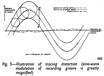
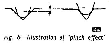
Fig. 5-6
TRACKING ERROR
Another important difference between the making and replaying of discs is that the pick-up stylus as it traverses the record does not follow the same path as the cutting stylus. The cutting stylus is set to move inwards in a straight line along a radius of the disc, whereas the pick-up stylus must necessarily be mounted on a pivoted tone arm, and must cross the record in an arc of a circle. The playback stylus is thus not always held at right-angles to the groove and the output will vary slightly. This effect is greater for large records, and can be reduced by using a. longer pick-up arm.
TURNTABLE DRIVING SYSTEMS
It is essential that the mechanical driving systems of disc-playing equipment should be accurately made, especially with stereophonic equipment. Rotation of the turntable must be extremely steady. These requirements must necessarily be very severe if the mechanical system is to match the performance expected from the acoustical and electronic equipment.
In a high-quality installation in which the loudspeaker is separate from the main chassis, the system can be mounted solidly to the motor board, and the motor board itself floated on rubber to ensure that no mechanical vibration is transmitted to the cabinet.
An unsuitable system can spoil the loudspeaker output in three objectionable ways: ‘wow', ‘flutter' and ‘rumble'.
Wow and flutter are produced by variations in the speed of the turntable. Those variations occurring at low frequencies are termed wow; flutter results from faster fluctuations. Slow variations can be caused by spindles and other rotating parts being loosely mounted or off center, so that the wow resulting is heard at regular intervals.
Unevenness of the drive, changes of friction (catching or slipping) and record slip can give rise to intermittent wow. Small irregularities are normally experienced when driving from a motor. Sudden changes in speed of as little as 0-5 will be clearly noticeable as flutter when a long note is being played. A sufficiently steady speed is usually achieved by providing a heavy turntable, or some other moving part, to act as a flywheel. Care should be taken to see that the speed-changing mechanism is not subject to undue wear. This can lead to wow or flutter after much use.
Rumble results because the mechanical parts run noisily. These parts should run sufficiently quietly for no objectionable rumbling to be heard at full gain when there is no other input signal.
TAPE EQUIPMENT
RECORDING AND PLAYBACK HEADS
Generally speaking, tape decks (with the exception of some of those used with the so-called ‘professional' equipment) combine the duties of recording and reproduction in a common head. The requirements of the recording and the playback heads are fundamentally the same and, as they are not required simultaneously, economy is served by combining them.
Modern heads are usually constructed of two semi-circular stacks of high-permeability laminations of about a half to one inch in diameter.
The stacks are assembled symmetrically with a ‘head gap' (against which the tape passes) of about five ten-thousandths of an inch or less, and an auxiliary gap, diametrically opposite the head gap, of about ten times that width.
Both gaps are filled with non-magnetic, metallic ‘shims' to prevent any accumulation in the gaps of magnetic material which may be rubbed off the tape by friction, and to maintain a linear relationship between the flux at the gaps and the current through the exciting coils of the head.
The impedance of these coils, which are placed symmetrically about each core, should, for recording, be low compared with the source impedance. This ensures, as far as is possible, a current which is independent of the frequency of the signal. For the playback process, however, maximum output voltages are to be gained from high-impedance windings. Any conflict between these requirements can be resolved by feeding the output from low-impedance coils into a step-up transformer.
Stereophonic playback heads consist fundamentally of two monaural heads mounted one on top of the other. Each head forms part of a complete playback system, the input signal for which is derived from one of the tracks of specially recorded stereophonic tape. Facilities for domestic stereophonic recording are seldom provided because of the difficulties to be encountered and the advanced technique required for such an operation.
ERASE HEADS
Although similarities exist between the erase head and the recording head, they differ in construction in two principal respects: Firstly, appreciable power (about 2 to 4W) is required for efficient erasure, while that necessary for the recording head is usually about 1mW. Hence the core of the erase head must be of a material having a higher point of magnetic saturation than the material in the recording head. Secondly, the longer the tape is under the influence of the erasing field, the more complete will be the cleaning. Thus the gap in the erase-head core should be considerably larger than in the core of the combined head. The erase gap is usually about fifteen thousandths of an inch wide. Normally there is no auxiliary gap in the core of the erase head.
TAPES
Modern magnetic tapes consist, generally, of a non-magnetic base (paper, cellulose acetate or p.v.c., for example) coated with a magnetic material. The base obviously needs to have strength and suppleness. The magnetic material (often red or black iron oxides) is a very finely divided powder mixed in some binding substance (lacquer, for instance), and the coating applied to the base material has to be very smooth. Unevenness in the surface of the tape will tend to cause broken contact with the heads, and consequently an undulating level of recording. The magnetic material needs a high coercivity to prevent, in particular, very large demagnetization losses at treble frequencies, and a high remanence to give a good level of recording.
Tapes are usually supplied in 5- or 7-inch reels, giving playing times, depending on the transport speed and the thickness of the tape, of between about 10 and 90 minutes. The standard width of the tape is a quarter of an inch, which normally allows for two (and sometimes four) adjacent recording paths. With stereophonic tapes, adjacent paths are used for the twin signals comprising the program. The total playing time of such tapes is therefore reduced by half.
TAPE TRANSPORT SYSTEMS
The basic requirement of the transport system is that a steady speed should be imparted to the tape. Momentary changes in this speed will cause ‘wow' or ‘flutter'. (Wow results from slow variations; flutter results from fast fluctuations: the dividing line is arbitrary.)
The actual speed of transport has a considerable bearing on the performance of the recording apparatus. The higher the speed, the better the performance at the higher frequencies. This is closely allied to the size of the gap in the recording head. But, of course, economically, great speeds are a disadvantage: the playing time of the tape is obviously reduced. Most transport systems are standardized for playing speeds of either 1 7/8, 3¾, 7½ or 15 inches of tape per second, with possibly, a choice of speeds.
AMPLITUDE DISTORTION
The non-linear relationship between the magnetism residing on the tape and the magnetic field inducing it, will cause considerable amplitude distortion in the recording.
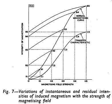
The curve OB3B5 in Fig. 7 shows a typical relationship between the magnetization produced in a magnetic material and the increasing magnetic field producing it. A field strength of H2 units, for example, would produce a degree of magnetization corresponding to the point B2, provided the material was unmagnetized initially, and also provided the field strength was not, at any time during its general increase from zero to H2, caused to diminish. The levels of magnetization corresponding to B1, B2, etc., are those obtaining when the field strengths are actually H1, H2, etc. These do not represent residual magnetism. If the fields are reduced from H1, H2, etc., to zero, the induced magnetism decreases along the paths B1R1, B2R2, etc., respectively, and the points R1, R2, etc., denote the degrees of residual magnetization, or remanence, induced in the magnetic material by maximum applied field. strengths of H1, H2, etc.
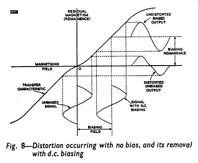
The curve OC3C5 plotted in Fig. 7 gives a typical ‘transfer' characteristic for a magnetic material; that is, it shows the intensity of residual magnetism (R1, R2, etc.) resulting from any given maximum magnetizing g field (H1, H2, etc.). Complete transfer characteristics for positive and negative magnetizing fields are shown in both Figs. 8 and 9.
It is obvious from these characteristic curves that the degree of residual magnetism is not a linear function of the maximum magnetizing field. Because of this non-linearity, any signal applied to the microphone would, on recording, suffer distortion. All signals (for example, the 'unbiased' sine wave shown in Fig. 8) would suffer ‘bottom-bend' distortion resulting in even harmonics of the fundamental appearing in the recording. Large signals would be further distorted by the magnetic saturation depicted by the flattening of upper sections of the characteristics, and the ‘clipped' reproduction would contain a high percentage of odd harmonics of the original.
The middle sections of the arms of the transfer characteristics are, however, approximately linear, and if the variation in the magnetic field strengths are confined to these portions, then the recording will be a relatively undistorted replica of the original sound. If a constant current is fed into the recording head together with the signal current, the effect is to ‘lift' the variations in the magnetizing field above the lower curvature of the characteristic (Fig. 8). The d.c. bias induces a constant degree of magnetization in the tape on which the audio variations are superimposed. Only the variations of the residual magnetism will appear on replaying the recording, so that the bias will not be translated into sound (in fact, some noise does result from the biasing remanence). But because of the limitation imposed by the saturation curvature of the characteristic, the fact that the bias magnetism is added to the audio magnetism means that the amplitude of the signal must be restricted quite considerably. The signal-to-noise ratio is thus lowered when d.c. bias is used.
This method of preventing amplitude distortion by introducing a constant biasing current into the recording head together with the signal current has been superseded by a method in which the direct current is replaced by a high-frequency, alternating current.
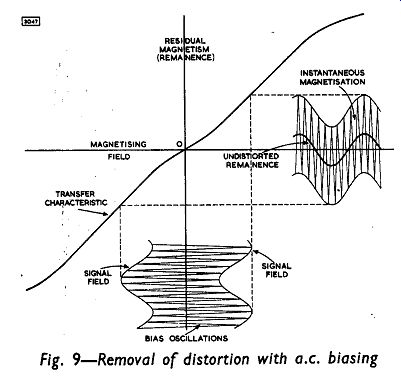
The result is a recording relatively free from harmonic distortion in which a good signal-to-noise ratio is maintained. No complete explanation of the mechanism of a.c. biasing has yet been accepted generally, but some idea of the process can be obtained from Fig. 9.
A feature of this method of biasing is the fact that no residual magnetism is induced in the tape by the a.c. signal, provided, of course, that these oscillations are free from even harmonic distortion.
As any point on the tape passes the gap in the recording head, it is subjected to a rapidly alternating magnetic field, the strength of which increases as the point approaches the gap and dies away as the point recedes. Such a process causes no remanence in the tape. Only the audio variations, which are superimposed on the a.c. field, cause any residual magnetism, and, because of the bias, this magnetism depends linearly on the audio signal. Thus, the tape is not loaded with any ‘wasted' remanence as it is when d.c. biasing is used. In addition to this, it will be seen from Fig. 9 that both linear sections of the transfer characteristic can be used. It follows then that the limitations imposed by d.c. biasing on the strength of the audio signal can be relaxed considerably without increasing the danger of approaching the saturation level of the tape. A.C. bias, therefore, reduces ‘bottom bend' distortion and, compared with d.c. biasing, gives an improved signal-to-noise ratio.
Figs. 7-9
Initially, an increase in the a.c. biasing current for a given signal strength lessens the distortion of the recorded signal and increases the level of recording. But too much bias will cause ‘top-bend' distortion and will also cause a lessening in the output, especially for treble signals. (The bias acts very much in the manner of the erase signal - see below.) A typical variation of output with bias current is shown in Fig. 10.
ERASING
It was stated above that the field associated with the a.c. biasing signal did not cause any residual magnetism in a tape passing through the field. If the tape is unmagnetized when the signal is applied, it will be unmagnetized when it has passed through the field. If the amplitude of the a.c. signal is sufficient to saturate the tape, then even if the tape is not unmagnetized originally, it will be so when it has travelled through the field.
This fact is used in the erase heads of most magnetic recording equipment. The tape is drawn through the strong local magnetic field arising from a high frequency alternating current in the erase head.
As each point of the tape travels into the field, it is saturated, and as each point recedes, it is subjected to a field strength which diminishes to zero some distance from the head, By this process it is cleaned of all previous magnetization.
OSCILLATOR COIL
The bias oscillator should generate a sine wave with negligible harmonic distortion to keep noise to a minimum. Symmetry in the waveform is essential. An asymmetrical sine wave has, in effect, a d.c. component made up of the difference between the positive and negative amplitudes of the sine wave. This will introduce noise in the recording and impart some 'wasted' remanence to the tape.
It is usual for the oscillator valve (tube) to provide both bias and erase currents. In most of the commercial tape decks, the combined record-playback head is usually of high impedance, while the impedance of the erase head may be high or low. To accommodate low-impedance erase heads, a separate oscillator output, in the form of a secondary winding to the oscillator coil, is required for matching purposes.
Because the characteristics of tape-recorder heads are not standardized, it is impossible to design an oscillator coil that will suit all types of head. Some degree of flexibility is possible if a tapped secondary winding is used, but the oscillator stage of a tape amplifier circuit may have to be adapted to a greater or lesser extent in accordance with the recommendations of manufacturers of tape heads and oscillator coils.
FREQUENCY RESPONSE
The degree of magnetization of the tape which results from recording with a current through the head which is constant at all frequencies is of the form shown by the curve ABC of Fig. 11. The reduced intensity in the treble region is attributable in the main to the self-demagnetization of the tape.
To outline the recording process briefly - the tape is drawn steadily past the recording head, and the field produced by the signal current in the head induces some degree of residual magnetism in the section of the tape nearest to the head. The amplitude of the signal governs the amount of magnetism, and the sense (whether positive or negative) controls the direction of the magnetism in each section.
On the basis of the molecular theory of magnetism, the ‘molecular' magnets in the tape are aligned by the magnetizing field: the strength of the field governs how many of these magnets are brought into line; the direction of the field dictates whether the alignment is with north or south poles leading.
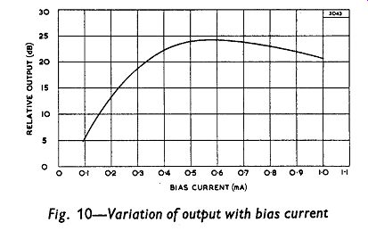
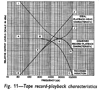
Fig. 10-11
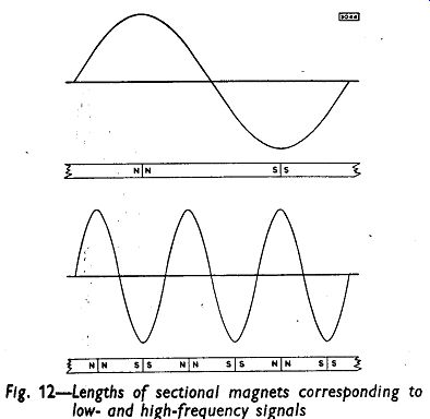
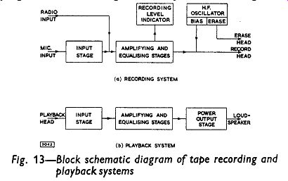
Fig. 12 - 13
The field set up by a sinusoidal signal current in the head would change direction regularly, so that the pattern of magnetism included in the tape would have adjacent sections of the tape with north and south poles leading alternately (see Fig. 12). Thus, the poles of each section of the tape would be adjacent to the like poles of the neighboring sections.
The length of these sectional magnets in the tape depends on the speed at which the tape passes the head, and on the frequency at which the magnetizing field changes direction. For a constant transport speed, the length varies inversely as the frequency of the signal. For low-frequency signals, the magnets are comparatively long, but for high frequencies they are short.
The ability of the tape to resist demagnetization depends, in part, on the length of these sectional magnets. If they are short, the opposing fields set up by the neighboring like poles will cause misalignment more readily than if they are long. Hence the demagnetizing effect is greater at the higher frequencies than at the lower ones, and consequently there will be less residual magnetism at the higher frequencies even if the signal amplitudes are constant throughout the frequency range.
For the playback process, the magnetized tape is drawn past the playback head at a constant speed, and the magnetic fields associated with the sections of the tape move and cut the coils of the head, thereby setting up voltages in the coils. The rate of change of the flux cutting the coils governs the voltage generated. Thus, the rapidly changing fields set up by the sections of the tape on which high-frequency sounds have been recorded must of necessity give rise to larger voltages than the sections containing low-frequency impressions. This is so, even if the impressions at both high and low frequencies have the same intensity of magnetization. The actual speed of the tape has no bearing on the relative levels of the output at the various frequencies. An increase in the transport speed simply multiplies all levels by the same amount.
The rate at which the playback voltage rises with frequency is equivalent to 6dB per octave. In Fig. 11, the line DEF indicates the frequency response of the playback head only. (A tape which has been ideally magnetized is assumed for this response curve.) The response curve for the recording head alone will depend on various practical considerations. For example, a tape made of a magnetic material of high coercivity is difficult to demagnetize, and if one is used, then the demagnetization losses at high frequencies will be less than if a low-coercivity tape is used. The use of a high coercivity tape, of course makes intentional erasing more difficult.
The response for the complete equipment, (that is, the response combining both recording and playback deviations) is indicated by the curve DEGH of Fig. 11. To obtain an equalized output from this response curve it is necessary to introduce boost at both ends of the frequency range. For ideal equalization, the compensating curve must be a mirror image of the curve DEGH, so that the equalizing response curve needs to be the curve IGJ.
There will be, in fact, further high-frequency losses encountered in tape recording. The tendency of the a.c. bias signal to act as an erasing signal during the recording process is more pronounced at high frequencies because the remanence is less deeply seated at these frequencies. Also, the physical dimensions of the gap in the playback head cause losses when the size of the sectional magnets and the gap are commensurate. (This is usually referred to as ‘gap effect'.) These combine to produce a more accentuated drop in the response curve in the treble region.
Unfortunately, equalization is not simply a matter of compensating for bass and treble deviations. Several performance requirements are in conflict, and a compromise is the best that can be achieved. A wide frequency response, low distortion or a high signal-to-noise ratio can each be obtained only at the expense of the others. Over a restricted range, an increase in the bias current, for example, lessens distortion, but causes treble attenuation and tends to lessen the signal-to-noise ratio. Furthermore, equalization is a function of the physical properties of the tape used. The equalization provided with any combination of tape deck and amplifier may, for example, provide a level response over a wide frequency range with one brand of tape, but may give rise to a large treble peak with another brand.
EQUALIZATION
A tape amplifier can be represented essentially by the block schematic diagram of Fig. 13. Normally, the design of both amplifying units will follow general a.f. practice, although attention must be paid to certain requirements of the equipment. Precautions will be required to minimize hum pick-up, and the overall signal-to-noise ratio should be at least 40dB.
The attenuation of the bass response in a tape recorder takes place mainly in the playback head. The treble response suffers its greatest losses in the recording process. Thus, in order to load the tape more or less evenly, it is best to provide treble boost in the recording amplifier and to apply bass boost in the playback amplifier. Some treble accentuation may also be required in the playback amplifier, but this has to be limited in order to avoid much amplification of background noise.