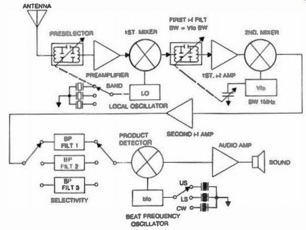
Fig. 1. Typical double-conversion block diagram.
The double-conversion scheme converts twice, just as its name implies (Fig. 1). First, it uses a fixed oscillator to convert to a relatively higher frequency than our previous 455 kHz, typically 5.5, 9, 10.7, or 21.4 MHz in order to place the image high enough to be readily attenuated in the preselector. This first i-f is filtered with the help of an electrical or crystal filter. To achieve proper selectivity, a second conversion is used at 455 kHz where already developed filters could be used. The second oscillator is a variable one, allowing for a typical 1 MHz (or 500 kHz) span.
It is important to know that the bandwidth of the first i-f has to be equal to that of the coverage of the second oscillator, in our case 1 MHz. The first i-f sometimes involves a manual preselector. This is usually called a variable bandpass i-f. In some more sophisticated receivers, this variable bandpass can be tuned electrically with the help of back-biased diodes which act as variable capacitors. The right amount of bias voltage is supplied to the varactors (variable capacitance diodes) to track the frequency being received. This voltage can be commanded from the Vfo through some rather fancy digital-to-analog techniques. A third mixer is used as the product detector, which is necessary for receiving cw and SSB signals. The third oscillator is called the bfo (Beat Frequency Oscillator).