AMAZON multi-meters discounts AMAZON oscilloscope discounts
One of the most important characteristics of a power supply is its voltage regulation. As was pointed out in the last chapter, voltage regulation relates to how the output voltage of a power supply changes with variations in the load current. A power supply that has good voltage regulation maintains an essentially constant output voltage with reasonable changes in its load current.
Voltage regulation of a power supply is generally expressed as a percentage which can be calculated as follows:
[formula coming soon]
Thus, if a power supply has a no-load output voltage of 275 volts and a full-load output voltage of 250 volts, its percentage of regulation is:
= 10%
Ideally, a power supply should have perfect voltage regulation, the output voltage remaining constant for changes in the output (load) current. Practical power supplies never reach perfection, although laboratory-type power supplies have been produced with voltage regulation of .001 % or better.
The voltage regulation of a conventional power supply, such as the one shown in FIG. 1, will be relatively poor for several reasons.
First, any variations in the a-c line input voltage will be reflected in changes of the output voltage. If the line voltage should increase, the output voltage will increase proportionally, and vice versa.
Secondly, as the load increases, the output of the power supply will drop. One cause of this is the filter ( mentioned in the last chapter). In the case of the capacitor-input filter, such as the one shown in FIG. 1, light loading will result in the output voltage of the supply nearly equaling the peak value of the output voltage from the rectifier. The output voltage drops as the loading is increased. The regulation can be improved by the use of a choke-input filter which will cause the supply output to remain near the average output voltage of the rectifier under varying load conditions. However, the output voltage will still change as the load current is varied.
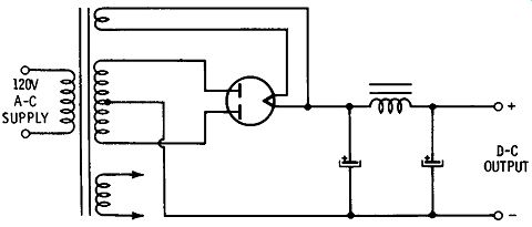
FIG. 1. Typical full-wave power supply.
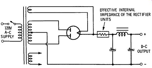
FIG. 2. Effect of power-supply internal impedance.
Third, a drop in power-supply output voltage is caused by the internal impedance of the rectifier and the power transformer. Any rectifier, whether it be a high-vacuum diode, gas-filled diode, or semiconductor diode, has an internal resistance (or impedance) ; this internal impedance causes a voltage drop in the rectifier. The effect is the same as though there were a resistor in series with the rectifier, as shown in FIG. 2. As with any resistor, when the current through it is increased, the voltage drop across it increases. Thus, as the current drawn from the power supply is increased, the voltage drop due to the internal impedance of the rectifier reduces the output voltage.
In addition, the power-transformer windings have resistances which are effectively in series with the power-supply output, thus further reducing the power-supply voltage output as the load current increases.
SHUNT VOLTAGE REGULATION
While the voltage regulation of the standard power-supply configuration of rectifier and filter is generally more than adequate for most applications, there are instances when better regulation is required.
There are a number of methods of improving the power-supply voltage regulation. Perhaps the simplest involves the use of a gas-filled shunt voltage-regulator tube.
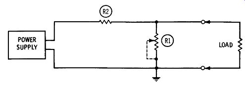
FIG. 3. Principle of shunt voltage regulation.
FIG. 3 shows the basic concept of the shunt voltage regulator.
Shunt voltage-regulation element R1 and series resistor R2 form a voltage divider, with the external load of the power supply connected to the junction of R1 and R2. When the load current increases, the voltage across the load drops because of the increased voltage drop across R2. Assuming for a moment that the value of R1 can be manually changed, then the voltage across the load can be returned to normal by increasing the value of R1 since this will decrease the current through R2 and, hence, the voltage drop across it. Conversely, a decrease in load current will increase the voltage across the load. This can be compensated for by decreasing the value of R1. There will be more current through R2, resulting in a greater voltage drop across it and less voltage applied to the load.
All that is needed is to replace the variable shunt resistor, R1, with a device that will automatically adjust its resistance in accordance with load changes so as to maintain a constant voltage across the load.
Such a device is the gas-filled voltage-regulator tube. It has the property of acting like a self-adjusting resistor that automatically changes value in order to maintain a constant voltage across itself.
FIG. 4 shows the physical construction of the gas-filled voltage regulator tube. It consists of only two electrodes-a cathode and an anode. The cylindrical cathode surrounds the anode, which consists simply of a single wire. The envelope is filled with either argon or neon.
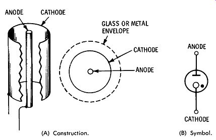
FIG. 4. Gas-filled voltage-regulator tube. (A) Construction. ( B1 Symbol.
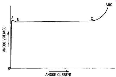
FIG. 5. Gas-filled voltage-regulator characteristics.
FIG. 5 shows the electrical characteristics of the gas-filled voltage regulator tube. As the voltage applied to the tube, through a current limiting resistor, is increased from zero toward point A, the full applied voltage appears across the tube. The reason is that, because the tube is not conducting, there is no current to cause a voltage drop across it.
When the voltage reaches the value indicated by point A, the tube suddenly ionizes, or "fires." At this time, the voltage across the tube drops to point B. The current through the tube can continue to increase, but the voltage across the tube remains essentially constant, as indicated by the line from B to C. If the applied voltage is increased greatly, the current through the tube will continue to increase until the point is reached where an arc will develop between cathode and plate.
At this point, the tube will be severely damaged, with permanent loss of its original regulating characteristics.
FIG. 6 shows how the gas-filled voltage regulator is used in a practical circuit. The output from the power supply is applied to the regulator tube (v-r tube) through current-limiting resistor R 1. The value of this resistor is selected to limit the current through the v-r tube to its recommended value. The regulated voltage is taken from the anode of the v-r tube and ground.
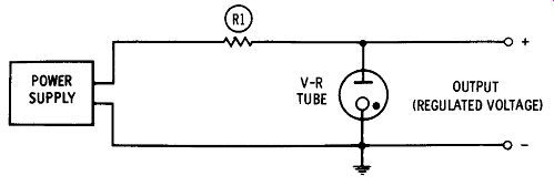
FIG. 6. Practical voltage-regulator circuit.
Most commercial voltage-regulator tubes are designed to provide a regulated voltage of between 75 and 150 volts, depending on the particular tube type. For example, the YR-75 will provide a regulated voltage of 75 volts, the YR- 105 will supply 105 volts, etc. Common v-r tubes are designed to operate in the current range from 5 to 40 ma.
It was noted earlier that a current-limiting resistor is required between the power-supply output and the v-r tube in order to limit the current through the tube to its rated value. The value of this resistor will depend on the output voltage of the power supply, the voltage rating of the v-r tube, and its current rating. It can be easily deter mined from the following formula: where,
R is the value of the series-dropping resistor, Es is the output voltage of the power supply, ET is the voltage drop across the v-r tube, I is the no-load current through the tube. This value is generally 40 ma for tubes such as the YR-75, YR-90, VR-105, YR-150, OA2, OB2, OC2, etc.
SERIES OPERATION OF GAS-FILLED V-R TUBES
It is possible to connect two or more v-r tubes in series in order to obtain a higher value of regulated voltage. FIG. 7 shows v-r tubes arranged in this manner. The regulated output voltage is now the sum of the individual ratings. Thus, the value of regulated voltage in Fig. 7 A is 75 + 150, or 225 volts. In FIG. 7B, the regulated voltage is 105 + 75 + 150, or 330 volts.
In determining the value of the series-dropping resistor for series connected v-r tubes, the same formula applies as in the case of a single tube, except that the sum of the individual v-r tube ratings is used for ET in the formula.
FIG. 7 also shows how individual output voltages can be obtained from series-connected v-r tubes. In this arrangement, the desired voltage is taken from the junction of the v-r tubes.
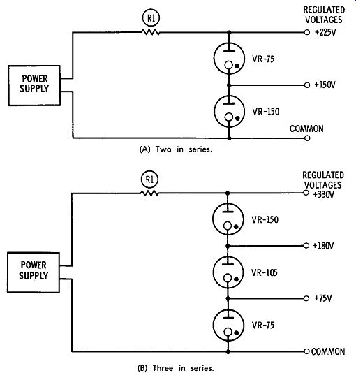
FIG. 7. Series-connected voltage-regulator tubes. (A) Two in series. (B)
Three in series.
PRACTICAL VOLTAGE-REGULATOR CIRCUITS
The following circuits illustrate practical applications of gas-filled regulator elements. When these circuits are connected to the output of an unregulated supply, they will provide a voltage regulation of approximately two percent.
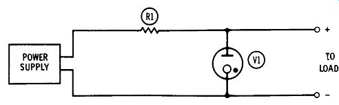
FIG. 8. Simple voltage-regulator circuit.
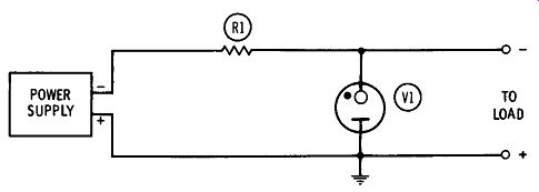
FIG. 9. Inverted voltage regulator.
FIG. 8 shows a simple gas-filled voltage regulator useful in such applications as providing stable voltage for the local oscillator in a communications receiver or for the screen grids of the output tubes in a hi-fi audio amplifier.
As shown in FIG. 8, the circuit consists simply of gas-filled voltage-regulator tube VI and series-dropping resistor R1. The value of regulated output voltage will depend on the choice of regulator tube. For a regulated output voltage of 75 volts, use an OA3/VR-75, or an OC2 if you would rather use a miniature tube. For a regulated output of 90 volts, use an OB3/VR-90. For 105 volts, an OC3/VR 105 may be used. For an output of 150 volts, use either an OD3/ VR150 or its miniature equivalent, the OA2.
No value of series-dropping resistor is given since it depends on the output voltage of the power supply with which this regulator is to be used. The proper value of series-dropping resistor can be easily calculated from the formula:
R = Es - ET I
where,
R is the value of the series-dropping resistor, Es is the unregulated power-supply output voltage, ET is the rated v-r tube operating voltage, I is the v-r tube no-load current.
If a negative regulated output voltage is desired-as, for example, a negative bias source-the circuit of FIG. 8 can be "inverted," as shown in FIG. 9.
Because of its simplicity, this circuit can be easily tucked away in side an existing piece of equipment.
Also see: