EQUIPMENT TEST REPORTS (Jul. 1977) : Hirsch -Houck Laboratory test results on the Rotel RT-1024 AM/ FM stereo tuner, Dual C919 cassette deck, TSI Models 110 and 120 speaker systems, Ortofon MC20 stereo phono cartridge and MCA-76 pre-preamplifier, and the Miida 3140 AM/FM stereo receiver.
JULIAN D. HIRSCH, Hirsch-Houck Laboratories
-------
Rotel RT-1024 AM/FM Stereo Tuner
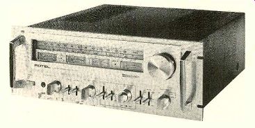
ROTEL'S line of deluxe audio components (including the RA-1412 integrated amplifier reviewed in STEREO REVIEW in February 1976) has been joined by a matching AM/FM stereo tuner with built-in Dolby de coding circuits. Like. its companions, the Rotel RT-1024 is large and distinctively styled.
The front panel, in satin-finish aluminum, has sturdy carrying handles and is slotted for mounting in a standard 19-inch rack. The dial scale and meters are behind a cutout on a heavy subpanel, which also contains the un usually large tuning knob.
Unlike most tuners, which have one or two meters, the RT-1024 has a complement of four which together occupy as much space as the dial scale above them. Two are the conventional FM channel-center indicator and the relative-signal-strength indicator for AM and FM. Another meter is used to set Dolby levels for an external recorder, using the 400-Hz calibration oscillator built into the RT-1024. It can be switched to read levels in either channel. (The tuner's Dolby circuits can be switched to provide either encoding or decoding functions for an external tape deck, as well as being used in their normal role for reception of Dolbyized FM broadcasts.) The fourth meter is an FM-multipath indicator whose deflection is proportional to the amount of multipath distortion in the received signal.
The operating controls of the Rotel RT-1024 include a pushbutton power switch and a headphone jack driven by a separate amplifier with its own volume control. One lever switch blends the high frequencies for noise reduction on weak stereo signals, and another switches the multipath meter on or off. There is a front-panel output-level knob controlling the rear outputs (in addition, there is another pair of audio outputs operating at a fixed level). The Dolby controls form a functionally separate group that includes the meter switch, a PLAY/REC function switch, and concentric knobs for calibration of the two channels. (Rotel will supply Dolby-level calibration cassettes with future RT-1024's.) A switch turns the Dolby system on for either external or FM use, simultaneously changing the de-emphasis of the tuner to the 25 microseconds required by the Dolby system. A three-position switch selects muting thresholds of 10 or 30 microvolts or turns off the muting circuit entirely. The last switch selects AM, FM with automatic stereo/mono switching, stereo FM only, and mono FM.
Red LED lights between the meters glow to show stereo reception and to indicate when the Dolby circuit is turned on.
In the rear of the Rotel RT-1024 are the fixed and variable audio-output jacks, input and output jacks for the Dolby system, a slide switch to turn on the 400-Hz Dolby calibration oscillator when matching the system to an external tape deck, and an FM 4-cit DETECTOR output jack for use with a possible future discrete four-channel FM decoder. There are insulated spring clips for the antenna connections and a hinged ferrite-rod AM antenna.
The single a.c. outlet is controlled by the tuner's power switch.
The performance specifications of the Rotel RT-1024 are as impressive as its appearance and control features. The FM front-end has a five-gang tuning capacitor, giving it an image-rejection specification of 110 dB. Other specs include 9.3-dBf (1.6 microvolts) IHF sensitivity in mono, a 1-dB capture ratio, and 80-dB alternate-channel selectivity. The PLL multiplex circuit is rated to provide 47 dB of stereo separation at 1,000 Hz and at least 35 dB from 30 to 15,000 Hz. Distortion is claimed to be less than 0.2 percent in mono and 0.3 percent in stereo, with signal-to-noise ratio (S/N) figures of 75 and 70 dB, respectively. The Rotel RT-1024 is 19 inches wide, 7 inches high, and 16 inches deep; it weighs 24.2 pounds. Price: $569.95.
Laboratory Measurements. The FM tuner section of the RT-1024 actually surpassed its rated IHF sensitivity specification, measuring an impressive 8.1 dBf or 1.4 microvolts (uV) in mono and 22 dBf (7 uV) in stereo, the latter being the automatic stereo/mono switching threshold. The 50-dB quieting sensitivity in mono was 9.3 dBf (1.6 uV) with 1.4 percent distortion; in stereo it was 34.5 dBf (29.2 uV) with 0.47 percent distortion. The S/N measurements were 69 dB in mono and 65.5 dB in stereo, and the respective distortion levels were 0.125 and 0.2 percent. The stereo distortion with L-R channel modulation was 0.63 percent at 100 Hz, 0.2 percent at 1,000 Hz, and 0.16 percent at 6,000 Hz.
The capture ratio was 1.6 dB at a 45-dBf (100 uV) input and 1.4 dB at 65 dBf (1,000 uV). AM rejection at these levels was 72 and 66 dB. Image rejection was not measurable, exceeding the 110-dB range of our instruments. The alternate-channel selectivity was 67 dB and adjacent-channel selectivity was 4.1 dB. The FM muting threshold in the 10- and 30-uV switch positions was 12 and 40 µV.
The tuner hum output was-65 dB, and the 19-kHz pilot carrier appearing at the audio outputs was 61 dB below the 100 percent modulation level.
The fixed audio output was 0.8 volt at 100 percent modulation, and the variable output could be adjusted up to 1.44 volts. The frequency response through the fixed outputs was ±0.7 dB from 50 to 15,000 Hz, down 1.9 dB at 30 Hz. Through the variable outputs the response was down 2.3 dB at 15,000 Hz and 3.2 dB at 30 Hz. Stereo channel separation was between 40 and 42.5 dB from 350 to 5,000 Hz, falling to 22 dB at 30 Hz and 34 dB at 15,000 Hz. The frequency response of the AM tuner section was unusually limited at the low-frequency end, being down 6 dB at 220 Hz and at 3,800 Hz.
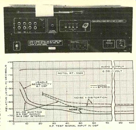
-------- The RT-1024's rear panel has fixed- and variable-level outputs plus jacks that provide access to the Dolby circuits for an external program source. ------- Rotel RT-1024, R.F TEST SIGNAL INPUT IN DBF
Comment. Our test sample of the Rotel RT-1024 was an early production unit, so it is possible that later production models will differ from it in some minor respects. However, there is no doubt that the tuner we tested had the best image rejection and sensitivity of any FM tuner we have tested up to now. In fact, the sensitivity borders on the theoretical limits for an FM tuner.
Although the selectivity, capture ratio, and S/N did not quite match the Rotel specifications, they were all good, and we have no reservations about the merit of the RT-1024, surely one of the "hottest" tuners on the market. We were puzzled by the fact that Rotel provided a switch on the panel to turn off the multipath meter, since the meter is not a dual-function one. Rotel tells us that for some reason their European distributors wanted it.
To put the matter into perspective, consider that the Rotel RT-1024 is probably one of the most sensitive FM tuners you can buy, has just about every feature you would expect to find on a Dolbyized FM tuner, has a head phone output with sufficient volume to make a separate amplifier unnecessary for anyone
who listens alone, and in general is as smoothly operating, finely constructed a product as we have seen. Its size and appearance suggest that it will occupy a prominent place in the homes of its owners, and that is as it should be. We cannot imagine hiding a tuner as hand some as this from view.
==============
Dual C919 Cassette Deck
DUAL'S second cassette deck, the Model C919, is a top-loading, single-motor, two-head machine based on the drive components used in the slightly more expensive Dual Auto-Reverse deck. The a.c. "continuous-pole" synchronous motor that powers the C919 is the same one that drives Dual's 1249 automatic turntable. The hard Permalloy re cord/playback head is said to have a life expectancy of at least 3,000 hours of operation.
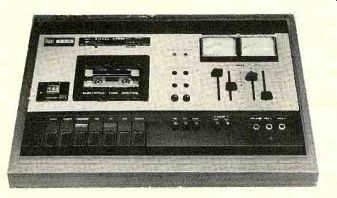
The black and silver control panel of the Dual C919 contrasts with a walnut-finish wooden base that makes the machine look somewhat larger than it really is. The cassette well has a clear window that exposes almost i he entire cassette to view. An angled mirror reflects the tape hubs of the cassette so that they can be seen from almost directly in front of the deck as well as above it.
Near the three-digit index counter is a reset pushbutton and a button that engages the MEMORY, which stops the tape when the counter reaches 000 in rewind mode. A plastic lens above the digits hinges upward to magnify them slightly and make them more visible when viewed from the front of the machine.
The transport controls are conventional "piano-key" levers in a row across the front of the panel. They can be operated in any sequence without going through STOP. The RE CORD and PLAY keys are coded with red and green stripes for easy identification; all the others are black and can be identified by the symbols and words on the panel above them.
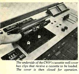
---- The underside of the C919's cassette-well cover has clips that receive a cassette to be loaded. The cover is then closed for operation.
Pressing the EJECT key causes the cassette-well door (carrying the cassette) to rise slowly under damped control. The cassette is retained in place even when the door is opened with the machine in a vertical position.
The right side of the panel contains two pairs of slider controls. These individually set the recording level of each channel for the LINE/DIN and microphone (MIC) inputs (LINE and mic sources can be mixed when recording). To the rear of the sliders are the two meters, illuminated softly in green when the recorder is on. They can be tilted upward slightly for better visibility. In addition to showing recording levels, they indicate the playback level before it is adjusted by the output-level control.
In the center of the panel are two pairs of screwdriver-adjusted controls and two small knobs that control headphone volume. One pair of screwdriver controls sets the recording gain for FM-Dolby operation, using the 400-Hz tone transmitted periodically by Dolby-equipped stations for calibration purposes. The other pair are line-output controls, setting the playback level supplied to the associated amplifier. A red RECORD light and a green DOLBY light are also located near the meters.
At the bottom front of the panel are five small black pushbuttons. Three set the bias and equalization for standard (Fe), chromium-dioxide (Cr), and ferrichrome (FeCr) tapes. The other two are Dolby controls, one of them turning on the Dolby circuits for re cording or playback and the other setting up the machine for processing Dolbyized FM signals. To record these, only the FM button is used. Since proper recording levels will presumably be the same for all such broadcasts, one simply presets them once with the screw driver adjustment and thereafter forgets them. The C919 can also be used to decode FM Dolby broadcasts, without recording them, by engaging both the FM and NR DOLBY buttons as well as the RECORD key with no cassette in the machine. (Of course, the receiver's TAPE MONITOR Mitch must be set to include the C919 in the signal path.) There are two quarter-inch jacks for medium-impedance dynamic microphones and a stereo headphone jack for phones rated from 4 to 2,000 ohms impedance. When microphones are plugged into both jacks, stereo recordings are made. When a single microphone is plugged into either jack, its output can be recorded in mono on either or both channels at the same time.
The Dual C919 has no on-off switch as such. Pressing any of the tape-motion keys also turns on the power to the machine. At the end of a tape, the transport disengages mechanically and shuts off. Preliminary recording-level adjustment can be done with just the RECORD key engaged or with both RECORD and PLAY engaged (the normal condition for making a recording) and the PAUSE key de pressed as well. The deck can be installed either horizontally or vertically (legs are sup plied for vertical mounting); it can even be hung on a wall with the hardware supplied.
The Dual C919 is 16 1/2 inches wide, 4 3/4 inches high, and 10 inches deep. It weighs approximately 14 1/4 pounds. Price: $450.
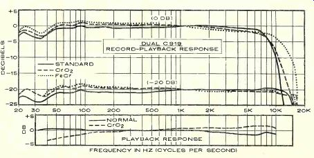
Laboratory Measurements. The playback frequency response of the Dual C9I9 was measured with the Nortronics AT 200 test tape for the Fe equalization mode (120 microseconds). It was within ±1 dB over the 31.5- to 10,000-Hz range of the tape. The FeCr and Cr equalization (70 microseconds) was measured with a Teac 116SP tape. The response was ±1.5 dB from 80 to 10,000 Hz, down about 3.5 dB at 40 Hz. The stereo cross talk from the left to the right channel was-46 dB at 1,000 Hz.
To reach a 0-dB indicated recording level, a LINE input of 43 millivolts (mV) or a mic input of 0.2 mV was needed. The corresponding playback output, with Maxell UD-XL I tape, was 0.8 volt. The overload points for LINE and mic were, respectively, 3.3 volts and 21 mV. The Dolby calibration marks are at +3 dB on the meters, and a standard Dolby-level tape indicated within 0.5 dB both channels. The meters also had accurate VU ballistics, so that a 0.3-second tone burst of 1,000 Hz, repeated once per second, gave exactly the same meter indication as a steady state signal of the same level-the standard test for VU characteristics.
The record-playback frequency response with Maxell UD-XL I tape (Fe) was within-±1 dB from 45 to 13,500 Hz at a-20-dB recording level, and within ±2 dB from 20 to 14,500 Hz. The chromium-dioxide tape response was measured with Sony CrO2 tape, and it was ±1.5 dB from 20 to 16,500 Hz. Ferrichrome tape (Sony) gave a rather similar result, within ± 2 dB from 20 to 15,500 Hz. Other high-quality tape formulations (including TDK SA and Audua, Maxell UD-XL II, and BASF LH Su per) were also tested and found to give generally similar results.
The playback distortion for a 1,000-Hz, 0-dB recording level was 0.75 percent with Fe, 1.4 percent with Cr, and 1.6 percent with FeCr tape. The reference 3 percent distortion level was reached at recording inputs of +6.5 dB, +4 dB, and +3 dB for the three tapes. At a 0-dB recording level, the high-frequency saturation was somewhat less with Cr than with Fe tape, and much less with FeCr than with either of the others.
The signal-to-noise ratio (S/N) was referred to the signal level corresponding to 3 percent playback distortion. The unweighted S/N for Fe, Cr, and FeCr tape was 56.5 dB, 55.5 dB, and 52 dB, respectively. With IEC "A" weighting, these figures improved to 60.7, 60, and 57.2 dB. With CCIR weighting, the SIN measurements were essentially the same as the unweighted readings. Using the Dolby system, the "A"-weighted S/N was 66.7, 65.5, and 63 dB. Finally, with CCIR weighting and Dolby, the S/N was 67.5, 65.5, and 62.5 dB. Through the MIC inputs, at maximum gain, the noise increased by 16 dB. At normal settings of the microphone gain, the increase was much less.
The C919 had one of the fastest wind-rewind modes we have seen in a cassette deck. It moved a C-60 cassette from end to end in 44 seconds (forward) or 47.5 seconds (rewind). The unweighted rms flutter was a very low 0.075 percent; it was 0.1 percent in a combined record-playback measurement.
The tracking of the Dolby circuits (between record and playback modes) was very good.
With the Maxell UD-XL I tape, switching the Dolby system in and out changed the record/ playback frequency response at levels of -20 and -30 dB by less than 1.5 dB at any point. 0.5 dB up to about 13,000 Hz.
Comment. In its individual specifications such as frequency response, S/N , flutter, and distortion, the Dual C919 compares very favorably with the most highly regarded cassette decks. In its totality, it easily earns a place as "one of the best" (a somewhat over worked phrase, but valid nevertheless).
The C919 is a bit different from most of its competitors. For one thing, to load the cassette one does not place it directly into the well but rather slides it into a pair of clips on the underside of the door. Otherwise, this is an easy deck to get used to, and quite difficult to misuse. It is obvious that human-engineering aspects have received careful attention.
For example, linking the power switch to the tape-transport controls makes good sense no more forgetting to shut off the machine.
--- FREQUENCY IN HZ (CYCLES PER SECOND)
The PAUSE control works exceptionally well, with no sign of a "chirp" or speed change on start-up. Unlike most pause keys, which start the tape when they are released after being pressed, the Dual device operates as it is being pressed, with a positive "click." In the design of the C919, Dual engineers have taken pains to make it entirely usable in either vertical or horizontal installations. Not only the removable mounting feet, but the tilting meters and index-counter lens contribute to this versatility. A bar across the cassette-well window at first annoyed us by partially blocking our view of the cassette from above, but it turned out to be part of a mirror assembly that makes the brightly marked hub shafts and their rotation clearly visible from directly in front of or above the deck as well as from all intermediate angles.
Another nice feature was the memory stop's being set to halt the tape at a counter reading of 000 instead of 999 as most such systems are. Thus, none of the program is lost on the replay, and there is less repetition of preceding material. We also noted that the headphone volume available from the lack was more than adequate, even with 200-ohm phones. Although we were not evaluating tapes, it seemed evident that a top-grade ferric-oxide tape such as Maxell UD-XL I gives the best overall results with this machine.
Slightly extended high-frequency response and headroom can be had with CrO2 or FeCr tape, but at some sacrifice of overall dynamic range and S/N and with increased distortion.
All in all, the Dual C919 is a pleasure to use.
In its listening and handling characteristics it can hold its own with any comparable ma chine, and it tops most of them. It is a special pleasure for us to work with a product in which everything works "just right"-and that certainly describes the Dual C919.
====================
TSI Models 110 and 120 Speaker Systems
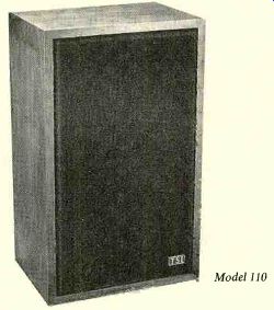
TECHNICAL SOUND INDUSTRIES Of Columbus, Georgia, a relatively new company in the audio marketplace, manufactures several loudspeaker systems. The most distinctive common feature of the TSI product line is its use of a passive radiator or "drone cone" in conjunction with the active woofer. The speakers also employ a tweeter with a 10-Model 110 ounce magnet structure, a 1-inch voice coil, and a 1-inch soft-dome diaphragm surrounded by silastic material.
The TSI speakers are housed in handsome walnut-veneer cabinets finished with a semi gloss lacquer. Push-type amplifier connectors are recessed into the rear of the cabinet, together with a continuously variable high-frequency level control. The dark-brown, foam-plastic grilles are held in place with Velcro fasteners and are easily removed.
We tested two TSI speaker systems, the Model 110 and the Model 120. Because of their many points of similarity, this report will deal principally with the less expensive Model 110 but will point out the differences we found between the two.
The TSI Model 110 has the appearance of a typical two-way bookshelf speaker. It measures 24 inches high, 14 1/2 inches wide, and 10 1/2 inches deep and weighs about 25 pounds.
The system consists of an 8-inch active woofer and a 12-inch passive radiator. The tweeter is the 1-inch soft-dome unit mentioned previously. Crossover between the two active drivers occurs at 3,000 Hz.
The TSI Model 120 is a slightly larger unit than the Model 110, being (as TSI describes it) a floor-standing unit which may also be used on a very sturdy bookshelf. It is nearly columnar in format-30 inches high, 143/4 inches wide, and 10 1/2 inches deep-and weighs about 48 pounds. The Model 120 is a three way system in which the low frequencies are handled by a 12-inch passive radiator similar to the one in the Model 110, together with a 10-inch woofer. It has a 5-inch cone mid range in a sealed sub-enclosure and the same dome tweeter used in the Model 110. Cross-over frequencies are 800 and 5,000 Hz, and both speakers have a nominal impedance of 8 ohms. Prices: Model 110, $169; Model 120, $209.
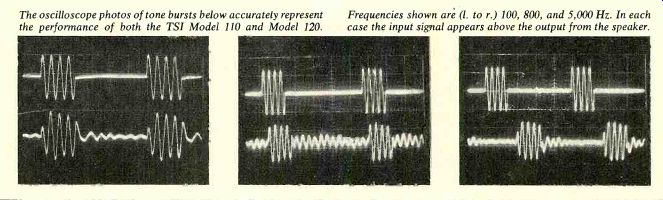
----------- The oscilloscope photos of tone bursts below accurately
represent the performance of both the TSI Model 110 and Model 120. Frequencies
shown are ( I. to r.) 100, 800, and 5,000 Hz. In each case the input signal
appears above the output from the speaker.
Laboratory Measurements. For virtually all our measurements and listening tests we used the maximum positions of the tweeter-level controls, which seemed to give the best results. The following data, unless otherwise stated, apply to the Model 110. The smoothed frequency response of the speaker system, measured in the reverberant field of the room, was remarkably uniform. It varied only about ±2.5 dB from 100 to 15,000 Hz; between 150 and 5,000 Hz the response variation was close to being within ±1 dB. The bass response was measured with close microphone spacing.
When the outputs of the driven and passive cones were combined, the response rose to a maximum of about +5 dB at 75 Hz. Below that, because of the contribution of the passive cone, the output remained within about 2.5 dB of the average mid-range level down to 26 Hz. The overall response of the speaker system was within ±4 dB from 25 Hz to beyond 15,000 Hz (our upper measurement limit).
With the tweeter-level control at its minimum setting, the output dropped above 3,000 Hz to a level of about-10 dB near 10,000 Hz.
We noted two pronounced "glitches" or jogs in the acoustic output of the active woofer cone. These occurred at 300 and 800 Hz and were also detectable in the impedance curve as slight jogs at those frequencies. The system impedance rose to peaks of about 40 ohms at 26 and 72 Hz, fell to about 6 ohms at 40 and 150 Hz, and rose to a broad peak of 20 ohms at 2,000 Hz before dropping to its minimum value of 5 ohms at 13,000 Hz.
The bass distortion was measured separately at the outputs of the active and passive cones with constant power levels corresponding to 1 and 10 watts into 8-ohm loads. In plot ting the measured distortion, we used the active cone value at frequencies where its output was dominant and the passive cone distortion at lower frequencies where its output exceeded that of the driven woofer. (The "crossover" between the two outputs was at about 70 Hz.) The distortion was high between 70 and 100 Hz (3 to 10 percent), quite low between 50 and 60 Hz (under 2 percent), and at 35 Hz it was about 3.5 percent at a 1-watt input. However, the Model 110 cannot be "pushed" in the bass region, since the distortion rises sharply with a 10-watt input.
The Model 110 was fairly efficient, delivering a 91-dB sound-pressure level (SPL) measured at a distance of 1 meter when driven by an octave of random noise centered at 1,000 Hz. The tone-burst response was fairly good at high and low frequencies, but we could see the effect of the woofer response "glitches" in the form of sustained ringing at 300 and 800 Hz.
The TSI Model 120 proved to be nearly identical to the Model 110 in its frequency response and in most of its other characteristics. The woofer "glitches" were slightly more prominent and could be seen in the reverberant-field measurement. The tone-burst response of the speaker system was virtually identical to that of the Model 110. The impedance curve had a single impedance peak off 28 ohms at 68 Hz (another peak evidently occurred below 20 Hz, which is beyond our measurement limit). The curve's shape resembled that of the Model 110, with an impedance of 6 ohms at 40 and 150 Hz, just under 5 ohms between 10,000 and 20,000 Hz, and a high area of 15 ohms at 1,200 Hz. The tweeter-level control also affected the mid-range driver, and at its minimum setting created a broad shelf at about-5 dB between 2,000 and 15,000 Hz.
The major difference between the Model 110 and the Model 120 was distortion in the bass area. The larger cones and enclosure volume of the Model 120 made a dramatic improvement in its low-frequency distortion, though not in its frequency response. At 1 watt, the distortion was 2 percent or less down to about 30 Hz, and only 8 percent at 20 Hz! At a 10-watt input it was higher in level, but still only 2.5 to 4 percent down to 40 Hz, reaching a maximum of 12.5 percent at 30 Hz. The efficiency of the Model 120 was identical to that of the Model 110.
Comment. Not surprisingly, the two TSI speakers sounded virtually identical. There was a trace of added low-frequency "feel" (not audible as "heaviness," however) in the output of the Model 120, but in spite of the presence of a separate mid-range driver in the 120, we could hear no differences between the two systems in the middle and high frequencies. In the simulated live-vs.-recorded test, which does not evaluate response below 200 Hz, the systems were absolutely identical.
The very flat overall frequency response measured for these loudspeakers would seem to imply an accurate reproduction capability.
This was confirmed by the great fidelity with which the speakers matched the sound of our "live" music source. They rank with the most accurate reproducers we have tested, with negligible coloration, emphasis, or de-emphasis of any part of the audio spectrum from 200 to 15,000 Hz and higher.
On occasion, we have found speakers that had similar qualities in this test but which failed to live up to their promise on full-range program material. Not so with the TSI speakers, which always sounded as good as their response curves suggested they should sound in other words, about as free of aberrations as a speaker can be. As for the woofer-response "glitches," we have occasionally seen such effects on other speakers, but not with such a high amplitude. But whatever their cause, we were never able to hear their effect on pro gram material, though we spent considerable time trying to do just that. Apparently these anomalies can legitimately be ignored.
Originally we intended to report on only one of these speakers, but after preliminary tests of both we could not decide which we preferred. Model 110 is obviously a good value for the money. On the other hand, the Model 120 can be played at considerably higher levels (we were not able to drive it into audible distress with peak amplifier outputs of at least 200 watts), and it has much lower bass distortion, if that is an important consideration. Either way, though you "pays your money and you takes your choice," in this case you can hardly go wrong.
======================
Ortofon MC20 Stereo Phono Cartridge and MCA-76 Pre-preamplifier
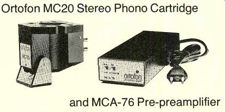
A GENERATION ago, the name Ortofon was synonymous with moving-coil phono cartridges. Since then, the company has added other designs to its product line, but the latest and finest Ortofon cartridge, the MC20, returns to the moving-coil principle. As is the case with most moving-coil cartridges, the stylus of the MC20 is not user-replaceable, but the entire cartridge can be exchanged for a new one at a considerable cost saving should the stylus become worn or damaged.
(The cartridge has a hinged guard to protect the stylus.) The MC20 stylus has a modified elliptical shape ("fine-line") that contacts the groove wall only along a thin edge-like the special styli developed for CD-4 applications-so as to give better high-frequency tracking and lower record wear. The stylus compliance is
------------
FREQUENCY IN HZ (CYCLES PER SECOND); PEAK VELOCITY IN CM/SEC OF TEST DISC
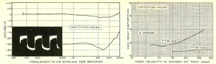
In the graph at left, the upper curve represents the smoothed, averaged frequency response of the cartridge's right and left channels; the distance (calibrated in decibels) between it and the lower curve represents the separation between the two channels. The inset oscilloscope photo shows the cartridge's response to a recorded 1,000-Hz square wave (see text), which indicates resonances and overall frequency response. At right is the cartridge's response to the intermodulation-distortion (IM) and 10.8-kHz tone-burst test bands of the ttr-102 and TTR-103 test records. These high velocities provide a severe test of a phono cartridge's performance. The intermodulation-distortion (IM) readings for any given cartridge can vary widely, depending on the particular IM test record used. The actual distortion figure measured is not as important as the maximum velocity the cartridge is able to track before a sudden and radical increase in distortion takes place. There are very few commercial phonograph discs that embody musical audio signals with recorded velocities much higher than about 15 cm/sec.
--------------
rated at 25 horizontally and 15 vertically (both times 10^-6 cm/dyne), and the equivalent tip mass is 0.5 milligram. The range of suggested tracking forces is from 1.5 to 2 grams, with 1.7 grams being recommended. The stated vertical tracking angle is the standard 20 degrees, and the total cartridge mass is 7 grams.
The stylus drives the generating coils through a cantilever whose diameter is stepped to provide stiffness with low mass.
The fixed end is supported and damped by a rubber suspension, and stylus motion "wiggles" the dual coil assembly in a powerful magnetic field. Each coil has only twenty eight turns of very fine wire, so that the output voltage at a recorded velocity of 5 centimeters per second (cm/sec) is a mere 70 microvolts. The d.c. resistance of the coils is 2.5 ohms per channel and the coil inductance is negligible.
Either a separate step-up transformer or a pre-preamplifier is needed to boost the cartridge output to a level suitable for a typical magnetic-phono preamplifier input. Ortofon makes both types of devices, and we tested the MC20 with their new MCA-76 pre-preamplifier. The MCA-76 has a voltage gain of 50, increasing the minute cartridge output to about 3.5 millivolts. Its input impedance of 75 ohms is a suitable load for the cartridge, and the amplifier's output impedance of less than 140 ohms permits it to drive long lengths of shielded cable and to be terminated by al most any preamplifier input circuit without effect on either the cartridge or the amplifier response. The maximum input rating of the MCA-76 is 6 millivolts (for 300 millivolts output), which assures that it will never be over loaded by the MC20 cartridge. Distortion in the MCA-76 is negligible (rated at less than 0.04 percent total harmonic distortion or 0.01 percent intermodulation distortion at maximum input), and the hum level is 120 dB be low its maximum operating level. Since that is almost 40 dB above the nominal cartridge output, the net signal-to-noise ratio (S/N) is of the order of 80 dB, highly noteworthy and surpassing the S/N of any preamplifier likely to be used with it.
The MCA-76 is a small black box with a self-contained a.c. power supply. A pushbutton at one end of the box shuts off the power when released, simultaneously bypassing the internal amplifier circuits. Thus, the MCA-76 can be left connected to a record player in which other types of cartridges will also be used. Another button inserts a CD-4 low-pass filter that rolls off the response sharply above 50 kHz to prevent possible interference with demodulator circuits by r.f. noise. There is also a fixed subsonic filter that cuts off the response sharply below about 7 Hz. Price: Ortofon MC20 cartridge, $120 ($65 on exchange basis for stylus replacement); MCA-76 pre-preamplifier, $170.
Laboratory Measurements. The Ortofon MC20 cartridge was tested through the MCA-76 pre-preamplifier, and some measurements were made on the MCA-76 alone as well. The cartridge was installed in the tone arm of a Thorens TD-126C record player.
(Note that the TD-126C may require a minor wiring modification to prevent a hum-producing ground loop from occurring when it is used with the MC20 cartridge.) Experimenting with different tracking forces indicated that 2 grams was needed to track the highest velocities on our test re cords, so that force was used throughout our tests. With the CBS STR 100 test record, the frequency response sloped gently downward, as the frequency increased, to about-2.5 dB between 5,000 and 10,000 Hz before rising to +1 to +2.5 dB at 20,000 Hz (the two channels were slightly different). The rise was obviously the lower skirt of a relatively undamped stylus resonance, but we did not extend our measurements above 20,000 Hz.
The channel separation was 20 to 25 dB up to 10,000 Hz and beyond, decreasing to 12 to 18 dB at 20,000 Hz. The square-wave response, checked with the CBS STR 112 record (which we have just started to use) showed fairly low-level sustained ringing at about 40,000 Hz. Ortofon states-and we have no reason to doubt this-that the ringing is inherent in the test record rather than the MC20 phono cartridge and visible only be cause of the MC20's extended high-frequency response.
The measured vertical tracking angle was 20 degrees, as rated. The cartridge output at 3.54 cm/sec was about 5.1 millivolts through the MCA-76, and the two channels matched within 0.4 dB. In our tracking tests, the cartridge was able to play all levels of the Shure 1TR-110 record at 2 grams, although there was a hint of mistracking at the highest level of the bass drum. The 60-micron level of the German Hi-Fi Institute test record was barely tracked at 2 grams. With the Shure TTR-103 record, the 10.8-kHz tone-burst distortion of the MC20 was low--1 percent or less at all velocities up to the 30-cm/sec maximum. The IM test of the Shure TTR-102 showed distortion increasing gradually from about 1.6 percent at velocities under 15 cm/sec to 4 percent at 27.1 cm/sec. There was no evidence of the severe mistracking that occurs with some cartridges at the higher levels of this record.
The MCA-76 amplifier had a gain of 34 dB (a voltage gain of 50), with a frequency response within ±0.3 dB from below 10 Hz to well beyond 50,000 Hz. The distortion at 1,000 Hz was less than 0.04 percent for outputs up to 100 millivolts, and only 0.1 percent at the maximum rated output of about 300 millivolts. The output clipped at 430 millivolts, corresponding to just over 8 millivolts input.
We could not measure the noise level of the MCA-76, since it was below the minimum levels readable on our instruments.
Comment. Having heard for years about the supposed special audible quality of the moving-coil cartridge, and yet having never been convinced of its reality, we looked for ward to hearing the Ortofon MC20. An extended listening experience failed to answer our questions completely, in that we never heard anything in the sound of the MC20 that we did not hear, more or less, when playing the same records with other good cartridges.
Similarly, a careful study of the measured performance of the MC20 showed that it is good-to-excellent in practically every respect but that it can also be surpassed in each performance category by one or more of the other fine cartridges we have tested recently.
In spite of this, the sound from the MC20 was so devoid of harshness or any identifiable coloration that we eventually came to prefer it to other cartridges whose characteristics were not demonstrably different. The MC20 cartridge has a clarity and sense of definition that set it somewhat apart from most others, al though we would not be able to prove this by objective measurements.
The MCA-76 pre-preamplifier contributes no noise to the record-playing process. Even at the highest levels we would normally use, lifting the pickup from the record groove resulted in dead silence from the speakers (at volume-control settings much higher than those for listening, some slight hiss could be heard).
The Ortofon MC20 is one of the best as well as one of the most expensive cartridges we have ever used (we include the cost of the MCA-76 in this assessment; the cartridge alone is not unusually expensive). We know of no other cartridge that, in combination with suitable speakers and amplifiers, will produce a greater sense of reality when playing a high-quality recording.
=======================
Miida 3140 AM/FM Stereo Receiver
Miida Electronics is a subsidiary of Marubeni Corp., a large Japanese manufacturer, and a full line of Miida audio components is now being distributed in this country.
Among them is the Model 3140 AM/FM stereo receiver, a medium-power unit with a full complement of features. The 3140 is rated at 40 watts per channel from 20 to 20,000 Hz into 8-ohm loads with no more than 0.5 percent total harmonic distortion (THD). Its FM tuner section has a phase-locked loop (PLL) multiplex demodulator for a high degree of stereo-channel separation in FM reception.
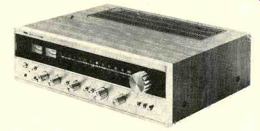
The external appearance of the Miida 3140 is conventional. The satin-finish aluminum front panel and matching fluted knobs contrast with a full-width "blackout" dial area.
The dial scales appear in green when the receiver is turned on, with two blue-lit meters to their left. One reads relative signal strength for AM and FM, and the other is an FM channel-center indicator. The large tuning knob is to the right of the dial area.
The other controls, occupying the bottom of the panel, include a headphone jack and pushbutton switches for power and for energizing the two independent sets of speaker outputs. An electronic protective circuit delays connecting the speakers for a few seconds after the power is first turned on in order to prevent audible transient thumps. It also cuts off the amplifiers instantly in the event of a short circuit or other malfunction that could damage the output transistors or the speakers.
A red light next to the power switch glows when this protective circuit is activated.
The bass and treble tone controls have eleven detented positions each, including a center "flat" setting. Pushbuttons turn on the high-cut filter and the loudness compensation and also parallel the two signal channels for mono operation. The balance control has a center detent and the volume control has forty-one detent steps, giving it a slightly "ratchety" feel that we have noticed on other receivers using a similar control. The function switch selects AM, FM, PHONO, or AUX signal sources. Separate pushbuttons for monitoring from either of two tape decks also permit dubbing from deck 1 to deck 2. A final button turns on the interstation-noise muting.
The signal inputs and outputs in the rear of the receiver are grouped according to function and are clearly marked. Insulated binding posts are used for speaker and antenna connections, and there is a hinged AM ferrite-rod antenna. The TAPE 1 connections are duplicated by a DIN socket, and the single a.c. outlet is switched (it is rated to handle only 50 watts, and should therefore be used only for a low-power device such as an equalizer or turntable). The Miida 3140 is supplied in a wood-grain-vinyl covered cabinet. It measures 19 inches wide, 5 1/2 inches high, and 14 inches deep; it weighs 25 pounds. Suggested retail price: $349.95.
Laboratory Measurements. The outputs of the Miida 3140, with a 1,000-Hz test signal driving 8-ohm loads, clipped at 54.6 watts per channel. The maximum output into 4 and 16 ohms was 62.4 and 37.2 watts, respectively.
Following the FTC-mandated one-hour pre conditioning period at one-third of rated power, the ventilation grille over the output transistors was only moderately warm.
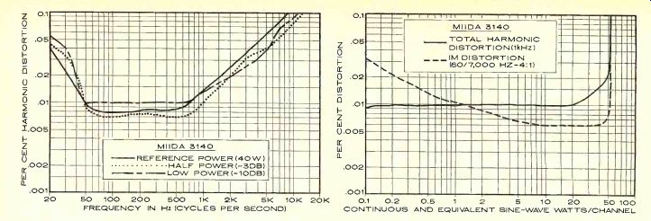
Total harmonic distortion (THD) at 1,000 Hz was about 0.01 percent from 0.1 watt to more than 20 watts output, increasing gradually to 0.019 percent at 50 watts and 0.08 percent at 55 watts (just before signal clipping occurred). The intermodulation distortion (IM) was extremely low-about 0.006 percent for most power outputs up to 50 watts, and only 0.025 percent at 55 watts. It was higher at ...
------------- FREQUENCY IN Hz (CYCLES PER SECOND) CONTINUOUS AND EQUIVALENT SINE-WAVE WATTS/CHANNEL
... very low power levels, reaching 0.18 percent at 4 milliwatts output.
Over the full audio-frequency range, the distortion of the Miida 3140 amplifier section varied only slightly from full rated power down to one-tenth rated power. Starting from about 0.05 percent at 20 Hz, it fell to 0.01 percent or less at 50 Hz and remained there until the frequency reached approximately 1,000 Hz. The THD then increased linearly with frequency to a maximum of about 0.2 percent at 20,000 Hz.
An input of 96 millivolts (mV) at the auxiliary inputs or 1 mV at the phono inputs was needed to develop a reference output of 10 watts. The unweighted noise level was a very low 83 dB below 10 watts through the auxiliary input and-75 dB through the phono in put. Phono overload occurred at a safe 110-mV input.
The bass tone-control characteristic had a sliding turnover frequency, shifting from about 150 Hz to about 500 Hz as the control was moved toward its extremes. The treble response curve was hinged at about 3,000 Hz.
The loudness compensation boosted both low and high frequencies moderately as the volume control was turned down. The high filter had a gradual 6-dB-per-octave slope, with its response 3 dB down at 7,000 Hz. The RIAA phono-response curve, when extended beyond the defined limits of 50 to 15,000 Hz, was flat within +1,-0.5 dB from 20 to 20,000 Hz.
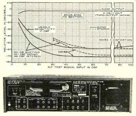
---- The Miida's rear panel has conventional phono jacks for inputs and tape-monitor connections, screw terminals for speakers.
Phono-cartridge inductance did not vary the response by more than 0.5 dB.
The FM-tuner section of the Miida 3140 had an IHF sensitivity of 11 dBf (2 microvolts, or µV) in mono and 31 dBf (20 µV) in stereo.
The latter signal level was the stereo switching threshold as well as the muting threshold (an unnecessarily high setting in view of the receiver's very good noise and distortion characteristics). The 50-dB quieting sensitivity was 14.1 dBf (2.8 uV) in mono with 1.6 percent THD. In stereo, it was 36 dBf (35 uV) with 0.43 percent THD. The signal-to-noise ratio (S/N) at a 65-dBf (1,000 µV) input was 70.5 dB in mono and 68 dB in stereo, with distortion measuring only 0.12 percent in both modes. Stereo distortion with L-R modulation was 0.32 percent at 100 Hz, 0.11 percent at 1,000 Hz, and 0.25 percent at 6,000 Hz. The other tuner-performance characteristics ranged from fair to good, in contrast to the very good sensitivity and distortion measurements. With a 65-dBf input, the capture ratio was 1.75 dB, with a very good 75-dB AM rejection. At a 45-dBf (100-µV) input, the capture ratio improved slightly to 1.5 dB, but the AM rejection was only 55 dB (an acceptable value but nowhere near as good as at higher signal-input levels).
The image rejection was 52 dB. Alternate-channel selectivity was only fair at 47 dB, and adjacent-channel selectivity was a minimal 1.4 dB. The power-line hum in the tuner's output was a very low -72 dB, but the 19-kHz pilot carrier leakage was a relatively high-38 dB.
The stereo FM frequency response was within ±1 dB from 30 to 15,000 Hz. Interchannel crosstalk was very uniform as well as low, with a channel separation of about 35 dB over most of the audio range. It varied from 38.5 dB at 30 Hz to 28 dB at 15,000 Hz. The FM signal-strength meter had a good logarithmic characteristic over its usable range, with the-reading going from 1 to 5 (maximum) as the signal level increased from 12 to 1,300 µV (27 to 68 dBf). The meter circuit saturated at the latter input, and there was no further change as the signal strength increased. The AM tuner's frequency response was down 6 dB at 90 and 2,600 Hz.
Comment. The audio section of the Miida 3140 is clearly its outstanding feature, with distortion so low under most conditions that it can be measured only with the finest laboratory instruments. The same level of excellence was apparent in other audio parameters, such as the accurate phono equalization, unaffected by cartridge inductance, and the exceptionally low noise and hum levels. By current standards, a 40-watt-per-channel rating is rather modest, but the Miida 3140 is rated so conservatively that a maximum output of 50 watts or more should be realizable at any audible frequency.
The FM tuner section, though probably adequate for the majority of users, is not up to the performance standards set by the audio section. The key FM parameters of sensitivity, distortion, stereo separation, and S/N are first-rate. However, the selectivity and image rejection of the tuner are no better than fair.
Although we did not experience any problems in use with insufficient selectivity or spurious responses, they could arise in some locations.
Also, the considerable 19-kHz pilot-carrier leakage could conceivably cause "birdies" with some tape decks when recording stereo FM broadcasts.
The tactile qualities of the Miida 3140--the "feel" of its controls--were very good. Even such a simple design feature as prominently visible index marks on the knobs sets this receiver apart from most others. One can see at a glance where the controls are set.
The smoothly operating FM muting system makes tuning the 3140 a quiet and uncritical process. There are no noise bursts when tuning on or off a signal, and when the tuning meter is centered the receiver is tuned as accurately as it has to be for low noise and distortion. Unfortunately, the FM dial is calibrated only at 2-MHz intervals, with intermediate markings that appear to have no relationship to the calibration numbers. As a result, considerable guesswork would be needed in a crowded metropolitan area to identify a particular station from the dial reading.
All things considered, the Miida 3140 is an attractive, well made, and competent receiver. Except for use in certain difficult FM receiving areas, it can easily hold its own in comparison with other, more widely known receivers in the same price class.
--------
Also see:
AUDIO BASICS--The Phonograph: Still on Top. RALPH HODGES
NOISE DILEMMA--Is it possible to have full dynamic range without noise? DANIEL QUEEN