The unijunction transistor (UJT) is a 3-terminal device which, unlike the bipolar transistor, has only one PN junction. Because the UJT exhibits negative input resistance, it is useful in a number of low-voltage devices-such as multivibrators, sawtooth generators, threshold detectors, pulse generators, and timers-which can exploit negative resistance and are simplified by use of the UJT instead of some other component.
The UJT is small and versatile and is manufactured in a number of types to meet various current and voltage demands. Although it functions most often by itself in such circuits as oscillators, the UJT is also found operating in conjunction with other devices such as silicon controlled rectifiers, triacs, and bipolar transistors.
Before working with UJTs, read the hints and precautions in Section 1.
UJT THEORY
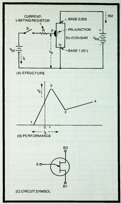
In the unijunction transistor (see Fig. 5-1A), an N-type silicon bar is provided with an ohmic base connection at each of its ends. These are designated base 1 and base 2. A PN function is created in the bar near base 2 and is designated the emitter (E). This junction acts simultaneously as an emitter and as a collector when the UJT is in operation. When the device is biased in the manner shown in Fig. 5-1 (A), the portion of the bar between base 1 and the junction provides the emitter action, whereas the portion between the junction and base 2 acts as a collector. This action is detailed in the following paragraphs.
When switch S is open, current IB2 from DC supply Vbb flows-from base 1 to base 2-through the silicon bar. In this state, the bar acts only as a resistance, and an approximately linear voltage gradient is set up; that is, the voltage drop between base 1 and any point along a straight line between the bases is proportional to the distance from base 1 to that point.
The voltage opposite the PN junction is higher than ^Vbb, since the junction is more than halfway along the bar.
The DC supply Vee is poled such that the P part of the emitter junction is positive with respect to base 1. When switch S is closed, forward current therefore flows through the junction, and holes are injected into the bar. Thus, the PN junction becomes an emitter. This hole current lowers the resistance of the bar between the emitter and base 1 and alters the voltage gradient.
If Vee and Vbb are correctly proportioned, the P-region then will be biased positive over its half nearest base 1, and this half will act as an emitter; and the P-region will be biased negative over its half nearest base 2, and this half will act as a collector. In this way, the single junction functions simultaneously as emitter and collector.
When emitter current IE is varied by adjusting voltage Vee from a small negative value, through zero, to the maximum allowable positive value, a response characteristic similar to Fig. 5-1 (B) is obtained: The resulting emitter-to-base-1 voltage (VE ) increases with IE from zero at point 1 to the peak point at 2, then decreases to the valley point at 3, and finally increases (as from 3 to 4) as IE further increases. The portion of the curve between 2 and 3 shows negative resistance, since here an increasing current produces a decreasing voltage drop. It is this negative-resistance characteristic that suits the UFT to its classic applications. On each side of the negative-resistance region, there is a conventional, positive-resistance region (1 to 2, and 3 to 4).
Figure 5-1 (C) shows the UJT circuit symbol.
(C) CIRCUIT SYMBOL
Fig. 5-1. Details of unijunction transistor.
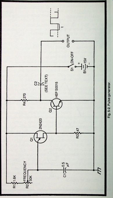
Fig. 5-2
PULSE GENERATOR
Figure 5-2 shows the circuit of a simple pulse generator comprised by a UJT oscillator (type 2N2420, Q) and a silicon bipolar output transistor (type HEP 50015, Q2). The output voltage of the UJT, taken across 47-ohm resistor R3, drives the bipolar transistor between saturation and cutoff, producing flat-topped output pulses. Depending upon the time off (t) of the wave, the output may be either narrow rectangular pulses or (as shown at the output terminals in Fig. 5-2) a square wave. The peak amplitude of the output signal is 4-15 volts.
The frequency, or repetition rate, is governed by the setting of a 50,000-ohm rheostat and the capacitance of C1. At the maximum-resistance setting of this control, the full resistance R1 4- R2 (i.e., 51.6 kilohms) is in the circuit with C1 = 0.5 u-F. For this combination, the frequency (f) = 47.2 Hz, and the time off (t) = 21.2 msec.
At the minimum-resistance setting of R2, ideally only R1 (1.6 K) is in the circuit; and for this condition, f = 1522 Hz, and t = 0.66 msec. For other frequency ranges, R1, R2, or C1-or all of them-may be changed:
t = 0.821 (R1 4- R2) C1 where t is in seconds, R1 and R2 in ohms, and C1 in farads, and f = 1/t.
The circuit draws 20 mA from the 15-volt DC supply, but this value is subject to variation with individual UJTs and bipolars. DC output coupling is shown in Fig. 5-2, but AC coupling may be provided by inserting a capacitor C2 in the high output lead, as shown by the dotted symbol. The capacitance of this unit should be between 0.1 and 1 u-F, the best value being the one that causes least distortion of the output wave when the generator is operated into a particular desired load device.
PULSE AND TIMING GENERATOR
A simple sawtooth generator with sharp spikes is useful in a variety of applications involving timing, synchronizing, sweeping, and so on. UJTs generate such waveforms in simple and inexpensive circuits. Figure 5-3 shows such a circuit which, though not a precision instrument, will give a good account of itself in shops and low-budget laboratories.
This circuit is essentially a relaxation oscillator, with outputs taken from the emitter and both bases. The 2N2646 UJT is connected in the classic oscillator circuit for these devices. The frequency, or repetition rate, is governed by the setting of the rate control rheostat, R2. When this control is set to its maximum-resistance point, the total resistance in series with timing capacitor C1 is the sum of the rheostat and the limiting resistance, R1 (that is, 54.6 kilohms), and the frequency is 219 Hz.
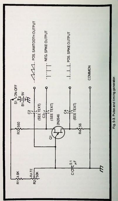
Fig. 5-3
When R2 is set to its lower end, the total resistance ideally is that of resistor R1, or 5600 ohms, and the frequency is 2175 Hz. Other frequency limits and tuning ranges may be obtained by changing R1, R2, C1, or all three.
Positive-spike output is obtained from base 1 of the UJT, negative-spike output from base 2, and positive sawtooth output from the emitter. While DC output coupling is shown in Fig. 5-3, AC coupling may be obtained by inserting capacitors C2, C3, and C4 in the output leads, as shown by the dotted symbols. These capacitances will be between 0.1 and 10 u-F, the value selected being determined by the maximum capacitance which can be tolerated with a given load device without degrading the output waveform.
The circuit draws approximately 1.4 mA from the 9-volt DC supply, B1. All resistors are 0.5-watt.
FREE-RUNNING MULTIVIBRATOR
The UJT circuit shown in Fig. 5-4 is similar to the relaxation oscillator circuits described in the two preceding sections, except that its constants have been chosen to give quasi-square-wave output resembling that of a conventional astable multivibrator employing transistors or tubes. The type 2N2646 unijunction transistor is a good performer in this arrangement.
Two output signals are provided: a negative-going pulse at base 2 of the UJT (see A in Fig. 5-4), and a positive-going pulse at base 1 (see B). The open-circuit peak amplitude of each of these signals is approximately 0.56-volt, but this may vary somewhat with individual UJTs. The 10,000-ohm rheostat, R2, must be adjusted for desired tilt or flatness of the top of the output wave. This control also affects the frequency, or repetition rate. With the values given here for R1, R2, and C1, the frequency is approximately 5 kHz for a flat-topped peak.
For other frequencies, change R1 or C1:
... where f is in Hz, R in ohms, and C in farads.
f = 1/0.821 RC
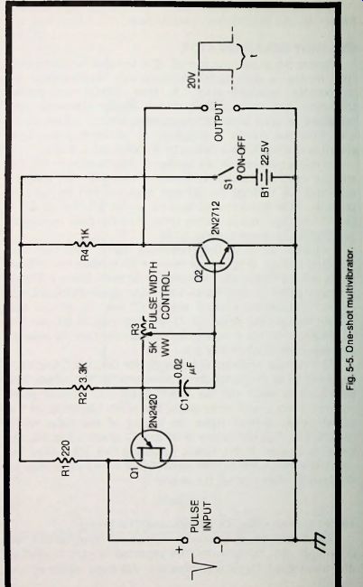
Fig. 5-4
... where t is in seconds, R3 in ohms, and C1 in farads.
The circuit draws approximately 11 mA from the 22.5-volt DC supply, B1, but this may be expected to vary somewhat with individual UJTs and bipolars. All fixed resistors are 1/2-watt.
The circuit draws approximately 2 mA from the 6-volt DC supply, B1. All fixed resistors are 1/2-watt.
ONE-SHOT MULTIVIBRATOR
Figure 5-5 shows the circuit of a one-shot multivibrator (this device is also called a single-shot multivibrator or monostable multivibrator). A type 2N2420 unijunction transistor and type 2N2712 silicon bipolar transistor are combined to give a single, constant-amplitude output pulse each time the circuit is triggered by an input pulse. This circuit is adapted from a design by W. Sowa and J. Toole.
In this arrangement, the voltage divider formed by R2, R3, and the base-to-emitter resistance of transistor Q2 charges capacitor C1 making its Q2 end negative and its Q1 end positive. This divider also applies to the emitter of Q1 a positive voltage that is a little lower than the peak voltage of the 2N2420 (see point 2 in Fig. 5-1B).
Initially, Q2 is in the conducting state; therefore, the resulting voltage drop across resistor R4 reduces the voltage at the output terminals substantially to zero. When a 20-volt negative pulse is applied to the pulse input terminals, Q1 "fires," pulling the emitter side of C1 down to ground and biasing the Q2 base negative. This action cuts off Q1, and the Q1 collector voltage rises rapidly to +20 volts (see the pulse at the output terminals in Fig. 5-5).
The voltage remains at this level for the time t taken for capacitor C1 to discharge through resistor R3. The output then falls back to zero, and the circuit rests until another pulse arrives. Time t, and accordingly the width (duration) of the output pulse, depend upon the setting of the pulse width control, R3; with the values of R3 and C1 given in Fig. 5-5, the range is 2 u-sec to 0.1 msec, assuming that R3 covers the resistance range 100 to 5000 ohms. Other time ranges may be obtained by changing C1, R3, or both:
t = R3 C1
Fig. 5-5
RELAXATION OSCILLATOR
A simple relaxation oscillator has a multitude of applications well known to all electronics persons. The unijunction transistor is a notably rugged and dependable active component for use in such oscillators. Fig. 5-6A shows the basic UJT relaxation-oscillator circuit, employing a type 2N2646 unit. The output is a slightly rounded sawtooth wave (Fig. 5-6B) whose peak amplitude is approximately equal to the supply voltage (here, 22.5 volts).
In this arrangement, current flowing from the DC source.
Bl. through resistor R1 charges capacitor Cl. A voltage VEe therefore gradually builds up across Cl. When this voltage equals the peak voltage of the 2N2646 (see point 2 in Fig. 5-1B), the UJT "fires." This discharges the capacitor, and the UJT cuts off. The capacitor then recharges, and the events are repeated.
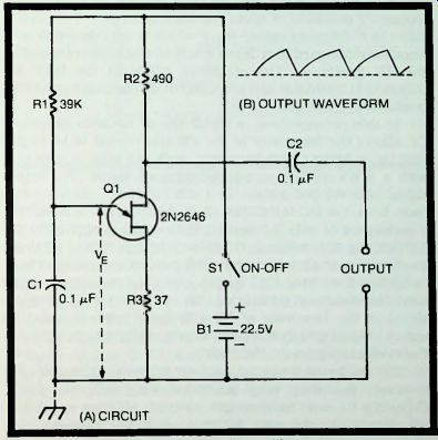
Fig. 5-6. Relaxation oscillator.
STANDARD-FREQUENCY OSCILLATOR
Figure 5-7 shows the circuit of a 100-kHz crystal oscillator which is usable in the conventional manner as a secondary frequency standard or spot-frequency generator. This circuit delivers a distorted output wave which is very desirable in a frequency standard in order to insure strong harmonics high in the RF spectrum. The combined action of the HEP 310 unijunction transistor and the 1N914 diode harmonic generator produces this distorted wave.
In this arrangement, a small 100 pF variable capacitor, C1. allows the frequency of the 100 kHz crystal to be varied slightly, to bring a high harmonic, such as 5 MHz, to zero beat with a WWV/WWVH standard-frequency signal. The output signal is developed across the 1 mH RF choke (RFC1) which must have low DC resistance (J. W. Miller type 73F103AF has a resistance of only 7.5 ohms). This signal is applied to the 1N914 diode (D1) which is DC-biased through R3 and R4 to the most nonlinear part of its forward conduction characteristic, to further distort the UJT output. When the oscillator is being used, the waveform adjust rheostat. R3. is set for the strongest signal at the harmonic of 100 kHz being used. Resistor R3 serves only as a current limiter to prevent direct connection of the 9-volt supply across the diode.
The oscillator draws 2.5 mA from the 9-volt DC supply. B1; however, this may vary somewhat with individual UJTs.
Capacitor C1 must be a midget air-type; all other capacitors are mica or silvered mica. All fixed resistors are 1-watt.
The charging and discharging of the capacitor and the resulting switching of the UJT on and off occur at a rate determined by the values of R1 and C1 (for the values given in Fig. 5-6, the frequency f = 312 Hz). For any other frequency, f = 1/(0.821 Ri C1 ), where f is in Hz. R1 in ohms, and C1 in farads. A rheostat of suitable resistance may be substituted for the fixed resistor, R1, if continuously variable frequency control is desired.
All resistors are 1/2-watt. Capacitors C1 and C2 may be any convenient low-voltage units; however, for good stability. C1 must be of good quality. The circuit draws approximately 6 mA from the 22.5-volt DC supply, B1.
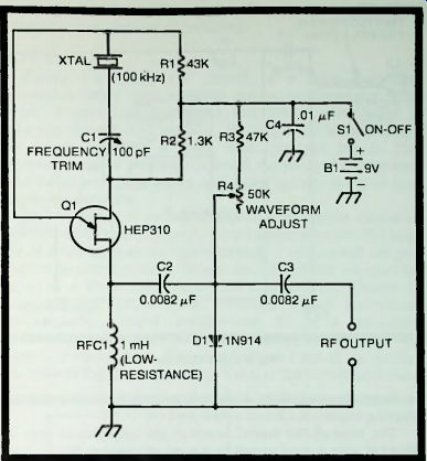
Fig. 5-7. Standard-frequency oscillator.
CW MONITOR
The CW monitor circuit shown in Fig. 5-8 is powered directly by RF pickup from the transmitter being monitored, and delivers an adjustable-tone audio signal to high-impedance headphones. The volume of this tone depends upon the strength of the RF. but will be found adequate even with low-powered transmitters.
The signal is sampled by the RF pickup coil, L1, which consists of 2 or 3 turns of insulated hookup wire mounted rigidly near the output tank coil of the transmitter. The RF energy is rectified by a shunt-diode circuit, consisting of blocking capacitor C1, diode D1, and filter resistor R1, and the resulting DC is used to power the HEP 310 unijunction transistor in a relaxation oscillator circuit. The output of this oscillator is applied to high-resistance headphones through coupling capacitor C3 and output jack J1.
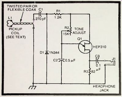
Fig. 5-8. CW monitor.
The tone of the signal heard in the headphones may be adjusted over a good range by means of rheostat R2; the tone frequency is approximately 162 Hz when R2 is set to 15,000 ohms, and is approximately 2436 Hz when R2 is set to 1000 ohms. The volume may be controlled by moving L1 nearer to or farther from the transmitter tank; usually, a location will be found that gives satisfactory volume for all general use.
The device may be assembled in a small, grounded metal box. In general, it may be located at any reasonable distance from the transmitter, if good-grade twisted pair or flexible coaxial cable is used and if L1 is coupled to the low end of the tank coil. All fixed resistors are 1/2-watt. Capacitor C1 should be rated to withstand safely the maximum DC voltage that might accidentally be encountered in the transmitter; C2 and C3. however, may be any convenient low-voltage units.
This type of RF-powered monitor has some advantage over the usual sine-wave type in that the distorted signal delivered by the UJT circuit is often more pleasing to the ear ...
Fig. 5-8 CW monitor
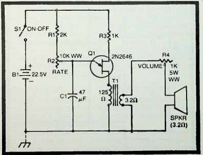
Fig. 5-9. Metronome.
... over long periods than is the flute-like sinusoidal tone. The distorted tone is certainly less lulling.
Metronome
Figure 5-9 shows the circuit of a fully electronic metronome based upon a 2N2646 unijunction transistor. This device is useful to musicians and others who desire a uniformly spaced audible beat. Driving a 2 1/2-inch speaker, this circuit provides a good. loud, pop-type signal. The metronome can be made quite small, the speaker and battery being its largest components, and. being battery-operated, it is completely portable.
The circuit is a variable-frequency relaxation oscillator which is transformer coupled to the 3.2-ohm speaker. The beat rate is adjustable from approximately 1 per second (60 per minute) to approximately 10 per second (600 per minute) by means of a 10.000-ohm wirewound rheostat, R2. Volume is adjustable by means of a 1000-ohm. 5-watt, wirewound rheostat, R4. Output transformer T1 is a miniature 125:3.2-ohm unit (Argonne AR-174 with primary center tap unused, or equivalent). The circuit draws 4 mA at the slowest beat rate of the metronome and 7 mA at the fastest beat rate, ...
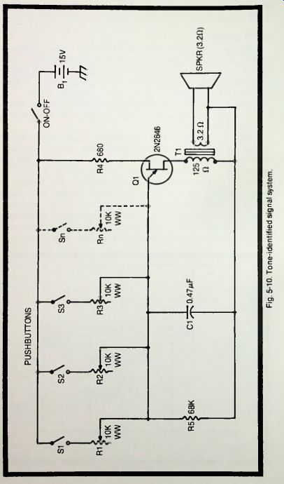
Fig. 5-10
... but this can vary with individual UJTs. A 22.5-volt battery (B1) will give good service at this low current drain.
Electrolytic capacitor C1 is a 50-volt unit. Resistors R1 and R3 are 1/2-watt, and rheostats R2 and R4 are wirewound (R4 is 5-watts).
TONE-INDENTIFIED SIGNAL SYSTEM
The circuit in Fig. 5-10 enables a separate tone signal to be obtained from each of several stations. These stations may consist of different doors in a building, different desks in an office, different rooms in a house, or any other places at which pushbuttons may be installed. The place that is signaling can be recognized from its distinctive tone, provided there are not too many stations and that the tones are far enough apart (for example. 400 Hz and 1000 Hz) that they are easily distinguishable by ear.
The circuit is a simple relaxation oscillator employing a type 2N2646 unijunction transistor to produce the signal and drive a loudspeaker. The tone frequency is set by capacitor C1 and one of the 10,000-ohm wirewound rheostats (R1 to Rn). When the rheostat is set to 10.000 ohms, the frequency is approximately 259 Hz; when the rheostat is set to 1000 ohms, the frequency is approximately 2591 Hz.
The oscillator is coupled to the speaker through output transformer T1, a miniature 125:3.2-ohm unit (Argonne AR-174 with primary center tap unused, or equivalent). The circuit draws approximately 9 mA from the 15-volt DC source, B1, but this will vary with individual UJTs.
In this circuit, all fixed resistors are 1/2-watt. The capacitor may be any convenient low-voltage unit. The wires to the pushbuttons will add some capacitance to C1, but in most instances this will be negligible.
TRIGGER FOR SCR
Figure 5-11 shows how a unijunction transistor may be used to trigger a silicon controlled rectifier. (See Section 1 for a discussion of silicon controlled rectifiers.) Here, a type HEP 310 UJT triggers a type HEP R1243 SCR.
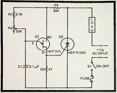
Fig. 5-11. Trigger for SCR.
In this arrangement, the UJT and SCR both are supplied from the AC power line. Current flow through resistor R4 drops the line voltage sufficiently that the UJT operates within voltage specifications. The timing circuit (R1-R2-C1) likewise is operated from the line. The load may be a motor or any other device which is to be operated on the DC output of the SCR.
On the positive half-cycle of line voltage, Q1 "fires" at any instant determined by the time constant of the R1-R2-C1 section and the characteristics of the UJT and switches Q2 into conduction. At the end of this half-cycle, Q2 switches off because of the zero line voltage and remains off during the negative half-cycle. At the same time, capacitor C1 discharges through the internal emitter-to-base-1 path of the UJT. The circuit is then ready to repeat the events.
Adjustment of rheostat R2 allows selection of the instant (point in the positive half-cycle) at which the SCR turns on (the SCR then conducts until the end of the positive half-cycle and all during the negative half-cycle). This phase-controlled action allows easy adjustment of the output current flowing through the load.
In this circuit, all fixed resistors are 1 watt. Capacitor C1 must withstand safely the peak value of the line voltage, and for maximum safety and dependability should be a 600-volt unit.